EP0102179B1 - Selectable focus ultrasonic transducers for diagnostic imaging - Google Patents
Selectable focus ultrasonic transducers for diagnostic imaging Download PDFInfo
- Publication number
- EP0102179B1 EP0102179B1 EP83304222A EP83304222A EP0102179B1 EP 0102179 B1 EP0102179 B1 EP 0102179B1 EP 83304222 A EP83304222 A EP 83304222A EP 83304222 A EP83304222 A EP 83304222A EP 0102179 B1 EP0102179 B1 EP 0102179B1
- Authority
- EP
- European Patent Office
- Prior art keywords
- transducer
- transducer assembly
- piezo
- conical
- electric material
- Prior art date
- Legal status (The legal status is an assumption and is not a legal conclusion. Google has not performed a legal analysis and makes no representation as to the accuracy of the status listed.)
- Expired
Links
- 238000002059 diagnostic imaging Methods 0.000 title description 2
- 239000000463 material Substances 0.000 claims description 20
- 235000014676 Phragmites communis Nutrition 0.000 claims description 12
- 239000002305 electric material Substances 0.000 claims description 10
- 239000000523 sample Substances 0.000 claims description 10
- 239000004593 Epoxy Substances 0.000 claims description 5
- 230000001747 exhibiting effect Effects 0.000 claims description 3
- 230000008878 coupling Effects 0.000 claims 3
- 238000010168 coupling process Methods 0.000 claims 3
- 238000005859 coupling reaction Methods 0.000 claims 3
- 239000004020 conductor Substances 0.000 claims 1
- 230000001419 dependent effect Effects 0.000 claims 1
- 230000009977 dual effect Effects 0.000 description 6
- RYGMFSIKBFXOCR-UHFFFAOYSA-N Copper Chemical compound [Cu] RYGMFSIKBFXOCR-UHFFFAOYSA-N 0.000 description 2
- 230000008901 benefit Effects 0.000 description 2
- 239000000919 ceramic Substances 0.000 description 2
- 229910010293 ceramic material Inorganic materials 0.000 description 2
- 229910052802 copper Inorganic materials 0.000 description 2
- 239000010949 copper Substances 0.000 description 2
- 238000013016 damping Methods 0.000 description 2
- 238000002592 echocardiography Methods 0.000 description 2
- 239000000945 filler Substances 0.000 description 2
- 230000007246 mechanism Effects 0.000 description 2
- 238000000034 method Methods 0.000 description 2
- 230000035945 sensitivity Effects 0.000 description 2
- 238000002604 ultrasonography Methods 0.000 description 2
- 230000004913 activation Effects 0.000 description 1
- 238000003491 array Methods 0.000 description 1
- 230000008859 change Effects 0.000 description 1
- 239000012141 concentrate Substances 0.000 description 1
- 230000000593 degrading effect Effects 0.000 description 1
- 230000000694 effects Effects 0.000 description 1
- 239000012530 fluid Substances 0.000 description 1
- 238000012886 linear function Methods 0.000 description 1
- 238000005259 measurement Methods 0.000 description 1
- 230000005855 radiation Effects 0.000 description 1
Images


Classifications
-
- G—PHYSICS
- G10—MUSICAL INSTRUMENTS; ACOUSTICS
- G10K—SOUND-PRODUCING DEVICES; METHODS OR DEVICES FOR PROTECTING AGAINST, OR FOR DAMPING, NOISE OR OTHER ACOUSTIC WAVES IN GENERAL; ACOUSTICS NOT OTHERWISE PROVIDED FOR
- G10K11/00—Methods or devices for transmitting, conducting or directing sound in general; Methods or devices for protecting against, or for damping, noise or other acoustic waves in general
- G10K11/18—Methods or devices for transmitting, conducting or directing sound
- G10K11/26—Sound-focusing or directing, e.g. scanning
- G10K11/32—Sound-focusing or directing, e.g. scanning characterised by the shape of the source
-
- G—PHYSICS
- G10—MUSICAL INSTRUMENTS; ACOUSTICS
- G10K—SOUND-PRODUCING DEVICES; METHODS OR DEVICES FOR PROTECTING AGAINST, OR FOR DAMPING, NOISE OR OTHER ACOUSTIC WAVES IN GENERAL; ACOUSTICS NOT OTHERWISE PROVIDED FOR
- G10K11/00—Methods or devices for transmitting, conducting or directing sound in general; Methods or devices for protecting against, or for damping, noise or other acoustic waves in general
- G10K11/18—Methods or devices for transmitting, conducting or directing sound
- G10K11/26—Sound-focusing or directing, e.g. scanning
-
- G—PHYSICS
- G10—MUSICAL INSTRUMENTS; ACOUSTICS
- G10K—SOUND-PRODUCING DEVICES; METHODS OR DEVICES FOR PROTECTING AGAINST, OR FOR DAMPING, NOISE OR OTHER ACOUSTIC WAVES IN GENERAL; ACOUSTICS NOT OTHERWISE PROVIDED FOR
- G10K11/00—Methods or devices for transmitting, conducting or directing sound in general; Methods or devices for protecting against, or for damping, noise or other acoustic waves in general
- G10K11/18—Methods or devices for transmitting, conducting or directing sound
- G10K11/26—Sound-focusing or directing, e.g. scanning
- G10K11/30—Sound-focusing or directing, e.g. scanning using refraction, e.g. acoustic lenses
Definitions
- This invention relates to ultrasonic transducers for diagnostic imaging and, in particular, to transducers of a novel geometric design with reduced sidelobe patterns.
- Ultrasonic transducers are used in ultrasonic diagnostic systems to transmit waves of ultrasonic energy into a patient's body. Tissue interfaces in the body reflect some of this energy back toward the transducer in the form of echoes. The echoes are received by the transducer and converted into electrical signals. These signals may be processed by associating them with their times of arrival to reconstruct an image of the tissue or make fluid flow measurements.
- a selectable focus transducer is shown in U.S. Patent 4,138,895.
- the transducer there shown comprises a disc divided into a center electroded region and an annular electroded region. A user can select just the center electrode for a large depth of focus, or the central and annular regions together for a smaller depth of focus.
- An acoustic lens provides the transducer arrangement with the desired aperture with point focal characteristics.
- Transducers like antennas, have transmissive characteristics that can be analyzed in terms of main and sidelobes. It is desirable in general to have small sidelobes for an ultrasonic transducer, since large sidelobes can result in the reception and introduction of noise in a reproduced ultrasound image.
- an ultrasonic transducer prefferably has good geometric focal characteristics which are adjustable so as to provide good resolution over a range of tissue depths. It is further desirable to reduce the transducer sidelobe patterns so as to minimize noise in the reproduced image.
- an ultrasonic transducer assembly having a novel geometric focal characteristic.
- the ultrasonic transducer assembly includes a piezo- electric material, the transducer exhibiting an effective radiating surface having a center point.
- the assembly is characterised in that said effective radiating surface has an aspheric, semi- conical configuration resembling a concave spherical surface with opposite sides, relative to the center of the surface, canted toward each other.
- This geometric focal characteristic provides a concentration of ultrasonic energy over a particular range of interest.
- the transducer material is divided into a center disc and an annular ring.
- the center disc When the center disc is activated, the range of optimal focus is located a relatively short distance from the transducer.
- the range of optimal focus is located at a relatively greater distance from the transducer.
- sidelobes of a transducer of the present invention are reduced by apodization, wherein damping material is located at the outer periphery on the back of the transducer.
- a proximity switch is provided in the transducer assembly to switch between the long and short focal ranges.
- the transducer electronics including the switch contacts are surrounded by a continuous shield.
- the proximity switch comprises a reed switch which is controlled by a magnet located external to the shield. The use of a proximity switch such as a reed switch thus permits the focal ranges to be switched without physically interrupting the shield and hence impairing the noise characteristic of the transducer assembly.
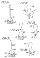
- a conical transducer is shown in cross-section.
- the transducer includes a conical surface 12 of piezoelectric ceramic material on a backer 10.
- the conical transducer exhibits an idealized aperture outlined at 16, which comprises a line of geometric focal points 14 emanating from the center of the transducer.
- Conical transducers are advantageous in that they exhibit a narrow region of sharply defined focal points. Their disadvantage is that the energy emitted by the conical surface is relatively evenly distributed over the line of focal points. It would be desirable to be able to concentrate the emitted energy in a particular region of the aperture, so as to improve the sensitivity of the transducer at a particular tissue depth of interest.
- FIG. 2a illustrates a spherical transducer in cross-section.
- This transducer includes a spherical surface 22 of piezoelectric material mounted on a backer 20.
- the spherical transducer exhibits an idealized aperture outlined at 26, which contains a single geometric focal point 24.
- the ultrasonic energy emitted from the spherical surface of the transducer 22 converges at this point, and diverges beyond it.
- the spherical transducer is capable of producing sharply focused images of tissue in the vicinity of the geometric focal point 24 by reason of the concentrated ultrasonic energy at the point.
- the aperture is only sharply focused at one point, with resolution degrading at regions removed from this point.
- a transducer constructed in accordance with the present invention is shown in cross-section in Figure 3a.
- the transducer there shown is neither conical nor spherical, but exhibits many of the advantages of these two transducer types while overcoming several of their shortcomings.
- the novel transducer of Figure 3a includes an aspheric surface 32 of piezoelectric material mounted on a backer 30.
- the shape of the surface 32 is difficult to visualize in three dimensions, but in two dimensional cross-section it resembles a spherical surface transducer which has been bent at the center point 38.
- the halves of the spherical surface on either side of the center point appear to be folded toward each other.
- the transducer exhibits the idealized aperture outlined at 36, in which most of the emitted ultrasonic energy is focused at points 34 in an elongated focal region.
- the ultrasonic energy emitted by the novel transducer is neither focused along the entire center line of the transducer, nor is it focused at a single point. Rather, it is concentrated in an elongated region of optimal focus in which tissue of a significant depth can be imaged with good lateral resolution.
- the elongated region in a constructed embodiment of the present invention can extend over a six to seven centimeter depth for a 19 mm, 3.5 MHz transducer.
- an aspheric surface piezoelectric element 300 includes a central area 312 which is electrically separate from an outer annulus 314.
- the piezo- electric material is mounted in a cylindrical mount 306.
- the inner area 312 may be activated alone, or a switch 316 may be closed to activate both areas 312 and 314 simultaneously to focus the transducer over different depths of focus.
- the concave front of the transducer 300 is filled in with an epoxy material to provide a flat face 302 on the transducer.
- the piezoelectric material exhibits a conical shape, and contains an annular groove which divides the material into an inner conical region 212 and an annular outer region 214.
- the center region 212 may be activated alone or together with the annular region 214 by closing a switch 216. When the switch 216 is open, the center region 212 will focus in the near field out to a point 218 at approximately 9 centimeters, and when the two regions are activated together, far field focusing is effected out to a point 201 at approximately 14 centimeters.
- the acoustic lens 210 On the face of the piezoelectric material is an acoustic lens having a spherical face 210.
- the combination of the conical piezoelectric material 212, 214 and the spherical faced lens provide the aspheric aperture characteristic of the embodiments of Figure 3a and 4.
- the concave lens is again filled in with epoxy to provide a flat face 208 on the transducer.
- the acoustic lens 210 was composed of a high acoustic impedance and velocity epoxy material, and the filler material at 208 was a lower acoustic impedance and velocity epoxy material.
- the conical piezoelectric transducer 212, 214 and the spherical acoustic lens provide the desired elongated focal region aperture, and the filler 208 forms a simple plano-convex lens which extends the focal zone to point 201. It follows from the principles of this embodiment that an aspheric transducer could also be made utilizing a spherical piezoelectric disc and a conical faced lens.
- the embodiment of Figure 5 is more easily manufactured than the other illustrated embodiments of the present invention. This is because a conical ceramic transducer can be readily manufactured and the spherical acoustic lens can be formed by a simple lapping technique.
- the embodiment of Figure 4 with its aspheric ceramic surface, could be formed by grinding the ceramic material with a precise, numerically controlled lathe, for example.
- the embodiment of Figure 6 is composed of a flat disc 400 of piezoelectric material, including a central disc 404 and an annular ring 406, the activation of which is controlled by a switch 416.
- the disc 400 is fronted with an acoustic lens 402 having an aspheric surface. This combination of piezoelectric material and aspheric lens will produce the same aperture as the embodiments of Figure 4 and 5.
- a conical transducer such as that shown in Figure 1a a will exhibit a lobe pattern as shown in Figure 1 b, with a large main lobe 40 and sizeable sidelobes 42 and 42'.
- the large sidelobes 42 and 42' are undesirable in an ultrasonic diagnostic system.
- the spherical transducer of Figure 2a will exhibit a more acceptable lobe pattern as shown in Figure 2b.
- the pattern there shown includes a large main lobe 50 and small sidelobes 52, 52'.
- the aspheric transducer of the present invention will exhibit a lobe pattern intermediate those of Figures 1b and 2b.
- the lobe pattern of a transducer of the present invention is improved in accordance with a further aspect of the present invention by providing backing material around the outer perimeter of the transducer as shown at 304 in Figures 4 and 5.
- This ring of backing material damps vibrations at the outer perimeter of the piezoelectric material thereby reducing the energy radiated from the perimeter of the piezo- electric material.
- the ring of backing material may be extended to back the central region 212 or 312 to damp vibrations at the perimeter of the central region when it is operated along.
- This damping technique causes the transducer to be a non-uniform radiator, which "smears" the small side lobes of the transducer as shown in Figure 3b, which illustrates a large main lobe 60 and side lobes 62, 62', which are approximately the same size as the side lobes 52, 52' of the spherical transducer.
- Figure 7a illustrates the focal pattern of a simple dual aperture spherical transducer, including a central spherical region 120 and an outer annular region 122.
- the transducer When both regions 120 and 122 of the transducer are activated simultaneously, the transducer exhibits an aperture outlined at 124, which narrows sharply at a focal region 125. Focusing is ineffective beyond the near field limit 129 of the transducer, which is approximately equal to the radius of the transducer squared, divided by the wavelength of operation.
- the near field limit 129 is thus a linear function of the area of the transducer, which in this case is the total of both regions 120 and 122.
- the aperture is as outlined by dotted lines 126.
- This aperture produces a focal region 127 closer to the transducer, with a near field limit at 128 by reason of the reduced area of the transducer.
- the aperture outlined at 126 does not narrow as sharply as the aperture outlined at 124, however, and the focal region 127 has a greater lateral dimension 1 than focal region 125. This is because the focus is changed by changing the near field limit from 129 to 128; the geometric focus remains the same, generally located slightly beyond the far focal region 125.
- Figure 7b illustrates the focal pattern of a simple dual aperture conical transducer having an inner conical surface 130 and an outer annular surface 132.
- the energy from surface 130 focuses along the broken line shown at 137 and bounded by dotted lines 136.
- both regions 130 and 132 are activated, the line of focal points is extended to include the points indicated at 135 as well as those at 137, bounded by dashed lines 134. Switching from operation using both regions to operation using only the center region 130 reduces the near field limit, since the transducer area changes, and also reduces the geometric focal length to only the focal points included in aperture outline 136. A line of distributed energy focal points is produced in both cases.
- Figure 7c illustrates the focal pattern of a dual focus aspheric transducer of the present invention.
- a narrow focal region 145 is produced at the narrow portion of the aperture outlined by dashed lines 144.
- the area of the full transducer provides a near field limit indicated at 129.
- the diameter d' of the central region 140 can be made larger than the diameter d of the equivalent central region 120 of the spherical transducer of Figure 7a.
- Several benefits result from use of a relatively larger central region. First, a larger region will transmit and receive more energy than a smaller region, thereby increasing the sensitivity of the transducer. Second, with a larger region there is less impedance change when switching from double to single region operation, which makes the tuning electronics coupled to the transducer simpler. And third, a larger central region 140 contributes to the narrowing effect on the aperture 146.
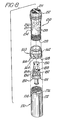
- the ultrasonic transducer of the present invention is conveniently mounted in a probe assembly such as that shown in Figure 8.
- the probe assembly there shown advantageously provides an electrically shielded environment which reduces the tendency to pick up stray electronic interference.
- the probe assembly also provides a means for switching the.focus of the transducer in a manner which does not interrupt the shielded environment. As the focus of the transducer is switched, the tuning of the transducer is also changed and a signal is provided which indicates the selected focal characteristics.
- the probe assembly of Figure 8 includes a forward plastic cylindrical section 150 with a closed acoustic window face 151.
- the aspheric transducer 152 is located behind the window 151.
- Leads 156 extend from the separate regions of the transducer.
- the interior of the cylindrical section 150 is lined with a nonmagnetic shield 154 such as copper.
- the rear portion of the cylindrical section 150 narrows to a smaller diameter as indicated by dividing ridge 157.
- Two dimples shown at 158 are provided on the outside of the narrow portion which form a portion of the detent mechanism of the switch.
- the end 159 of the cylindrical section 150 is open.
- a plastic ring 160 slides over the narrow portion of the cylindrical section 150 up to the ridge 157.
- a small ball 162 which rides between the dimples 158 and snaps into them to provide a detent mechanism for the ring.
- a groove 168 is formed around the inner surface of the ring to hold a magnet 164 in a predetermined position relative to the ball bearing 162.
- a small pin 166 extends from the inner surface of the ring at the bottom of the ring.
- a rear cylindrical section 170 slides over the remainder of the narrow portion of section 150.
- a recessed collar 176 is then located under the ring 160.
- the collar 176 has a slot 174 in it so that pin 166 can move from one end of the slot to the other as the ring 160 is turned. The pin and slot thereby provide a stop for the ring to permit the ring to be turned only through the arc of the slot.
- the wires 156 from the transducer are soldered to a small printed circuit board 190, mounted on an r.f. connector 180.
- the r.f. connector 180 is inserted into the open end 159 of the section 150 up to the lip 181 of the connector.
- Mounted on the connector at a plastic ring 183 are three reed switches 184, 186 and 188.
- the reed switches are wired to the printed circuit board 190.
- the r.f. connector 180 and copper shield 154 provide a completely shielded cavity for the wiring, printed circuit board, switches, and board components in the inside of the section 150.
- the ring performs three switching functions in the probe assembly.
- the focal characteristics of the transducer are switched between short focus using only the central disc of the transducer, and long focus by connecting the central disc and annular ring of the transducer together to be activated simultaneously.
- the tuning of the circuitry on circuit board 190 is switched to match the respective electrical characteristics of the transducer in the two operating modes.
- a resistance value on the circuit board is changed to produce a signal indicative of the operating mode, which signal is coupled out through the connector along with signals to and from the transducer.
Landscapes
- Physics & Mathematics (AREA)
- Engineering & Computer Science (AREA)
- Acoustics & Sound (AREA)
- Multimedia (AREA)
- Ultra Sonic Daignosis Equipment (AREA)
- Transducers For Ultrasonic Waves (AREA)
Description
- This invention relates to ultrasonic transducers for diagnostic imaging and, in particular, to transducers of a novel geometric design with reduced sidelobe patterns.
- Ultrasonic transducers are used in ultrasonic diagnostic systems to transmit waves of ultrasonic energy into a patient's body. Tissue interfaces in the body reflect some of this energy back toward the transducer in the form of echoes. The echoes are received by the transducer and converted into electrical signals. These signals may be processed by associating them with their times of arrival to reconstruct an image of the tissue or make fluid flow measurements.
- In many applications of ultrasound it is desirable to be able to focus the waves or beams of . ultrasonic energy at a particular tissue depth. Such focusing permits the reconstruction of images of good lateral resolution at a particular tissue depth of interest, for instance. Focusing may be done in the signal processing, as in the case of phased arrays, or may be provided by the geometric shape of the transducer. Geometric focusing advantageously eliminates much electrical complexity usually required to achieve the same result in the signal processing section of the system. However, geometric focal characteristics are idealized normally for only a single focal point or line of focal points, which restricts the range of good image resolution.
- This restriction has been overcome by transducers having selectable geometric focal characteristics. A selectable focus transducer is shown in U.S. Patent 4,138,895. The transducer there shown comprises a disc divided into a center electroded region and an annular electroded region. A user can select just the center electrode for a large depth of focus, or the central and annular regions together for a smaller depth of focus. An acoustic lens provides the transducer arrangement with the desired aperture with point focal characteristics.
- Another important characteristic of transducers are sidelobe patterns. Transducers, like antennas, have transmissive characteristics that can be analyzed in terms of main and sidelobes. It is desirable in general to have small sidelobes for an ultrasonic transducer, since large sidelobes can result in the reception and introduction of noise in a reproduced ultrasound image.
- It is desirable, then, for an ultrasonic transducer to have good geometric focal characteristics which are adjustable so as to provide good resolution over a range of tissue depths. It is further desirable to reduce the transducer sidelobe patterns so as to minimize noise in the reproduced image.
- In accordance with the present invention, an ultrasonic transducer assembly is provided having a novel geometric focal characteristic. The ultrasonic transducer assembly includes a piezo- electric material, the transducer exhibiting an effective radiating surface having a center point. The assembly is characterised in that said effective radiating surface has an aspheric, semi- conical configuration resembling a concave spherical surface with opposite sides, relative to the center of the surface, canted toward each other. This geometric focal characteristic provides a concentration of ultrasonic energy over a particular range of interest.
- In accordance with a preferred embodiment of the present invention, the transducer material is divided into a center disc and an annular ring. When the center disc is activated, the range of optimal focus is located a relatively short distance from the transducer. When both the center disc and annular ring are activated, the range of optimal focus is located at a relatively greater distance from the transducer.
- In accordance with a further preferred aspect of the present invention, sidelobes of a transducer of the present invention are reduced by apodization, wherein damping material is located at the outer periphery on the back of the transducer.
- In accordance with yet another preferred aspect of the present invention, a proximity switch is provided in the transducer assembly to switch between the long and short focal ranges. In order to prevent the introduction of noise into the received echo signals, the transducer electronics including the switch contacts are surrounded by a continuous shield. In a preferred embodiment of the present invention, the proximity switch comprises a reed switch which is controlled by a magnet located external to the shield. The use of a proximity switch such as a reed switch thus permits the focal ranges to be switched without physically interrupting the shield and hence impairing the noise characteristic of the transducer assembly.
- The use of a proximity switch in a dual-aperture. ultrasonic probe assembly, but not incorporating the aspheric, semiconical effective radiating surface of the present invention is described and claimed in our copending European patent application No. 86 20 0472.8, which is divided out of the present application.
- In the drawings:
- FIGURES 1 a and 1 b illustrate idealized aperture and lobe patterns for a conical surface transducer, known from the prior art;
- FIGURES 2a and 2b illustrate idealized aperture and lobe patterns for a spherical surface transducer, known from the prior art;
- FIGURES 3a and 3b illustrate idealized aperture and lobe patterns for a transducer constructed in accordance with the present invention;
- FIGURES 4, 5, and 6 illustrate different embodiments of transducers constructed in accordance with the present invention;
- FIGURES 7a, 7b, and 7c illustrate idealized dual aperture spherical, conical and aspheric transducers; and
- FIGURE 8 is an assembly drawing of a transducer probe comprising a transducer in accordance with the present invention.
- Referring first to Figure 1a, a conical transducer is shown in cross-section. The transducer includes a
conical surface 12 of piezoelectric ceramic material on abacker 10. The conical transducer exhibits an idealized aperture outlined at 16, which comprises a line of geometricfocal points 14 emanating from the center of the transducer. Conical transducers are advantageous in that they exhibit a narrow region of sharply defined focal points. Their disadvantage is that the energy emitted by the conical surface is relatively evenly distributed over the line of focal points. It would be desirable to be able to concentrate the emitted energy in a particular region of the aperture, so as to improve the sensitivity of the transducer at a particular tissue depth of interest. - Figure 2a illustrates a spherical transducer in cross-section. This transducer includes a
spherical surface 22 of piezoelectric material mounted on a backer 20. The spherical transducer exhibits an idealized aperture outlined at 26, which contains a single geometricfocal point 24. The ultrasonic energy emitted from the spherical surface of thetransducer 22 converges at this point, and diverges beyond it. The spherical transducer is capable of producing sharply focused images of tissue in the vicinity of the geometricfocal point 24 by reason of the concentrated ultrasonic energy at the point. However, the aperture is only sharply focused at one point, with resolution degrading at regions removed from this point. - A transducer constructed in accordance with the present invention is shown in cross-section in Figure 3a. The transducer there shown is neither conical nor spherical, but exhibits many of the advantages of these two transducer types while overcoming several of their shortcomings. The novel transducer of Figure 3a includes an
aspheric surface 32 of piezoelectric material mounted on abacker 30. The shape of thesurface 32 is difficult to visualize in three dimensions, but in two dimensional cross-section it resembles a spherical surface transducer which has been bent at thecenter point 38. The halves of the spherical surface on either side of the center point appear to be folded toward each other. The transducer exhibits the idealized aperture outlined at 36, in which most of the emitted ultrasonic energy is focused atpoints 34 in an elongated focal region. Unlike the conical and spherical transducers, the ultrasonic energy emitted by the novel transducer is neither focused along the entire center line of the transducer, nor is it focused at a single point. Rather, it is concentrated in an elongated region of optimal focus in which tissue of a significant depth can be imaged with good lateral resolution. The elongated region in a constructed embodiment of the present invention can extend over a six to seven centimeter depth for a 19 mm, 3.5 MHz transducer. - Different embodiments of transducers constructed in accordance with the present invention are shown in Figures 4, 5 and 6. In Figure 4, an aspheric surface
piezoelectric element 300 includes acentral area 312 which is electrically separate from anouter annulus 314. The piezo- electric material is mounted in acylindrical mount 306. Theinner area 312 may be activated alone, or aswitch 316 may be closed to activate bothareas transducer 300 is filled in with an epoxy material to provide aflat face 302 on the transducer. - A preferred embodiment of the present invention is shown in Figure 5. In this embodiment the piezoelectric material exhibits a conical shape, and contains an annular groove which divides the material into an inner
conical region 212 and an annularouter region 214. Thecenter region 212 may be activated alone or together with theannular region 214 by closing aswitch 216. When theswitch 216 is open, thecenter region 212 will focus in the near field out to apoint 218 at approximately 9 centimeters, and when the two regions are activated together, far field focusing is effected out to a point 201 at approximately 14 centimeters. - On the face of the piezoelectric material is an acoustic lens having a
spherical face 210. The combination of the conicalpiezoelectric material acoustic lens 210 was composed of a high acoustic impedance and velocity epoxy material, and the filler material at 208 was a lower acoustic impedance and velocity epoxy material. The conicalpiezoelectric transducer - The embodiment of Figure 5 is more easily manufactured than the other illustrated embodiments of the present invention. This is because a conical ceramic transducer can be readily manufactured and the spherical acoustic lens can be formed by a simple lapping technique. The embodiment of Figure 4, with its aspheric ceramic surface, could be formed by grinding the ceramic material with a precise, numerically controlled lathe, for example.
- The embodiment of Figure 6 is composed of a
flat disc 400 of piezoelectric material, including acentral disc 404 and anannular ring 406, the activation of which is controlled by aswitch 416. Thedisc 400 is fronted with anacoustic lens 402 having an aspheric surface. This combination of piezoelectric material and aspheric lens will produce the same aperture as the embodiments of Figure 4 and 5. - It is desirable for a transducer to exhibit a radiation/reception pattern with reduced sidelobes, since signals received from the sidelobe regions can introduce noise which will degrade image quality. A conical transducer such as that shown in Figure 1a a will exhibit a lobe pattern as shown in Figure 1 b, with a large main lobe 40 and sizeable sidelobes 42 and 42'. The large sidelobes 42 and 42' are undesirable in an ultrasonic diagnostic system.
- The spherical transducer of Figure 2a will exhibit a more acceptable lobe pattern as shown in Figure 2b. The pattern there shown includes a large
main lobe 50 andsmall sidelobes 52, 52'. - The aspheric transducer of the present invention will exhibit a lobe pattern intermediate those of Figures 1b and 2b. The lobe pattern of a transducer of the present invention is improved in accordance with a further aspect of the present invention by providing backing material around the outer perimeter of the transducer as shown at 304 in Figures 4 and 5. This ring of backing material damps vibrations at the outer perimeter of the piezoelectric material thereby reducing the energy radiated from the perimeter of the piezo- electric material. For the dual focus, two area transducers of Figures 4 and 5, the ring of backing material may be extended to back the
central region main lobe 60 andside lobes 62, 62', which are approximately the same size as theside lobes 52, 52' of the spherical transducer. - A comparison of idealized apertures of different dual focus transducers is shown in Figures 7a, 7b and 7c. Figure 7a illustrates the focal pattern of a simple dual aperture spherical transducer, including a central spherical region 120 and an outer
annular region 122. When bothregions 120 and 122 of the transducer are activated simultaneously, the transducer exhibits an aperture outlined at 124, which narrows sharply at afocal region 125. Focusing is ineffective beyond thenear field limit 129 of the transducer, which is approximately equal to the radius of the transducer squared, divided by the wavelength of operation. Thenear field limit 129 is thus a linear function of the area of the transducer, which in this case is the total of bothregions 120 and 122. - When the spherical transducer is switched to operate in the near field using only the center region 120, the aperture is as outlined by
dotted lines 126. This aperture produces afocal region 127 closer to the transducer, with a near field limit at 128 by reason of the reduced area of the transducer. The aperture outlined at 126 does not narrow as sharply as the aperture outlined at 124, however, and thefocal region 127 has a greater lateral dimension 1 thanfocal region 125. This is because the focus is changed by changing the near field limit from 129 to 128; the geometric focus remains the same, generally located slightly beyond the farfocal region 125. - Figure 7b illustrates the focal pattern of a simple dual aperture conical transducer having an inner
conical surface 130 and an outerannular surface 132. When the innerconical surface 130 is activated alone, the energy fromsurface 130 focuses along the broken line shown at 137 and bounded bydotted lines 136. When bothregions lines 134. Switching from operation using both regions to operation using only thecenter region 130 reduces the near field limit, since the transducer area changes, and also reduces the geometric focal length to only the focal points included inaperture outline 136. A line of distributed energy focal points is produced in both cases. - Figure 7c illustrates the focal pattern of a dual focus aspheric transducer of the present invention. When both the central region 140 and the outer
annular region 142 of the transducer of Figure 7c are activated, a narrowfocal region 145 is produced at the narrow portion of the aperture outlined by dashedlines 144. The area of the full transducer provides a near field limit indicated at 129. - When the transducer of Figure 7c is switched to operation using the central region 140 alone, the area of the transducer is reduced, which moves the near field limit to the line indicated at 128. But the geometric focus of the transducer also changes, since its effective radiating surface is aspheric. Thus the aperture of the central region appears as outlined by
dotted lines 146, containing a relatively- narrowfocal region 147. Thefocal region 147 is laterally narrower thanregion 127 of the spherical transducer by reason of the relocation of the geometric focus of the transducer to an area closer to the transducer. Good lateral resolution is therefore provided in bothregion 145 andregion 147. - Since the geometric focus moves closer to the transducer when operation is switched from two region to central region operation, the diameter d' of the central region 140 can be made larger than the diameter d of the equivalent central region 120 of the spherical transducer of Figure 7a. Several benefits result from use of a relatively larger central region. First, a larger region will transmit and receive more energy than a smaller region, thereby increasing the sensitivity of the transducer. Second, with a larger region there is less impedance change when switching from double to single region operation, which makes the tuning electronics coupled to the transducer simpler. And third, a larger central region 140 contributes to the narrowing effect on the
aperture 146. - The ultrasonic transducer of the present invention is conveniently mounted in a probe assembly such as that shown in Figure 8. The probe assembly there shown advantageously provides an electrically shielded environment which reduces the tendency to pick up stray electronic interference. The probe assembly also provides a means for switching the.focus of the transducer in a manner which does not interrupt the shielded environment. As the focus of the transducer is switched, the tuning of the transducer is also changed and a signal is provided which indicates the selected focal characteristics.
- The probe assembly of Figure 8 includes a forward plastic
cylindrical section 150 with a closedacoustic window face 151. Theaspheric transducer 152 is located behind thewindow 151. Leads 156 extend from the separate regions of the transducer. The interior of thecylindrical section 150 is lined with anonmagnetic shield 154 such as copper. The rear portion of thecylindrical section 150 narrows to a smaller diameter as indicated by dividingridge 157. Two dimples shown at 158 are provided on the outside of the narrow portion which form a portion of the detent mechanism of the switch. Theend 159 of thecylindrical section 150 is open. - A
plastic ring 160 slides over the narrow portion of thecylindrical section 150 up to theridge 157. On the inner surface of thering 160 is asmall ball 162 which rides between thedimples 158 and snaps into them to provide a detent mechanism for the ring. Agroove 168 is formed around the inner surface of the ring to hold amagnet 164 in a predetermined position relative to theball bearing 162. Asmall pin 166 extends from the inner surface of the ring at the bottom of the ring. - With the
ring 160 in place on the forwardcylindrical section 150, a rearcylindrical section 170 slides over the remainder of the narrow portion ofsection 150. A recessedcollar 176 is then located under thering 160. Thecollar 176 has aslot 174 in it so thatpin 166 can move from one end of the slot to the other as thering 160 is turned. The pin and slot thereby provide a stop for the ring to permit the ring to be turned only through the arc of the slot. - Finally, the wires 156 from the transducer are soldered to a small printed
circuit board 190, mounted on an r.f.connector 180. The r.f.connector 180 is inserted into theopen end 159 of thesection 150 up to thelip 181 of the connector. Mounted on the connector at a plastic ring 183 are threereed switches circuit board 190. When the connector is inserted in thesection 150 in the proper position, the reed switches are located under either side of the arc traversed by themagnet 164 as thering 160 is turned. When the ring is turned to one detent position themagnet 164 is located overreed switches reed switch 188 to close it. The r.f.connector 180 andcopper shield 154 provide a completely shielded cavity for the wiring, printed circuit board, switches, and board components in the inside of thesection 150. - Turning the ring performs three switching functions in the probe assembly. First, the focal characteristics of the transducer are switched between short focus using only the central disc of the transducer, and long focus by connecting the central disc and annular ring of the transducer together to be activated simultaneously. Second, the tuning of the circuitry on
circuit board 190 is switched to match the respective electrical characteristics of the transducer in the two operating modes. Third, a resistance value on the circuit board is changed to produce a signal indicative of the operating mode, which signal is coupled out through the connector along with signals to and from the transducer.
Claims (11)
Applications Claiming Priority (4)
| Application Number | Priority Date | Filing Date | Title |
|---|---|---|---|
| US40054782A | 1982-07-21 | 1982-07-21 | |
| US400551 | 1982-07-21 | ||
| US400547 | 1982-07-21 | ||
| US06/400,551 US4445380A (en) | 1982-07-21 | 1982-07-21 | Selectable focus sphericone transducer and imaging apparatus |
Related Child Applications (1)
| Application Number | Title | Priority Date | Filing Date |
|---|---|---|---|
| EP86200472.8 Division-Into | 1983-07-20 |
Publications (2)
| Publication Number | Publication Date |
|---|---|
| EP0102179A1 EP0102179A1 (en) | 1984-03-07 |
| EP0102179B1 true EP0102179B1 (en) | 1987-09-16 |
Family
ID=27017086
Family Applications (2)
| Application Number | Title | Priority Date | Filing Date |
|---|---|---|---|
| EP83304222A Expired EP0102179B1 (en) | 1982-07-21 | 1983-07-20 | Selectable focus ultrasonic transducers for diagnostic imaging |
| EP86200472A Expired - Lifetime EP0196139B1 (en) | 1982-07-21 | 1983-07-20 | Dual aperture ultrasonic transducer probe assembly |
Family Applications After (1)
| Application Number | Title | Priority Date | Filing Date |
|---|---|---|---|
| EP86200472A Expired - Lifetime EP0196139B1 (en) | 1982-07-21 | 1983-07-20 | Dual aperture ultrasonic transducer probe assembly |
Country Status (4)
| Country | Link |
|---|---|
| EP (2) | EP0102179B1 (en) |
| AU (1) | AU572464B2 (en) |
| DE (2) | DE3373739D1 (en) |
| IL (1) | IL69293A0 (en) |
Cited By (1)
| Publication number | Priority date | Publication date | Assignee | Title |
|---|---|---|---|---|
| US20220373372A1 (en) * | 2021-05-19 | 2022-11-24 | Honeywell International Inc. | Fluid sensor for bubble and occlusion detection |
Families Citing this family (8)
| Publication number | Priority date | Publication date | Assignee | Title |
|---|---|---|---|---|
| EP0102179B1 (en) * | 1982-07-21 | 1987-09-16 | Technicare Corporation | Selectable focus ultrasonic transducers for diagnostic imaging |
| FR2559266B1 (en) * | 1984-02-02 | 1986-07-04 | Comp Generale Electricite | FOCUSED ACOUSTIC WAVE DEVICE FOR STUDYING THE STRUCTURE OF AN OBJECT |
| JPH02159266A (en) * | 1988-12-14 | 1990-06-19 | Matsushita Electric Ind Co Ltd | ultrasonic probe |
| JPH02215452A (en) * | 1989-02-17 | 1990-08-28 | Toshiba Corp | Calculus crushing device |
| JPH03176040A (en) * | 1989-09-29 | 1991-07-31 | Terumo Corp | Ultrasonic diagnostic apparatus |
| WO1999010875A2 (en) * | 1997-08-23 | 1999-03-04 | Valeo Schalter Und Sensoren Gmbh | Ultrasonic converter with a board for an electric circuit arranged in the longitudinal direction of the converter |
| DE10114819A1 (en) * | 2001-03-26 | 2002-10-10 | Siemens Ag | Method for improving the signal reception of an ultrasonic proximity switch and ultrasonic proximity switch with improved signal reception |
| US20240181278A1 (en) * | 2021-03-15 | 2024-06-06 | Resonant Acoustics International Inc. | Apodizing backing structures for ultrasonic transducers and related methods |
Family Cites Families (11)
| Publication number | Priority date | Publication date | Assignee | Title |
|---|---|---|---|---|
| US3193198A (en) * | 1963-11-12 | 1965-07-06 | Honeywell Inc | Control apparatus |
| JPS4963401A (en) * | 1972-10-18 | 1974-06-19 | ||
| US4016751A (en) * | 1973-09-13 | 1977-04-12 | The Commonwealth Of Australia Care Of The Department Of Health | Ultrasonic beam forming technique |
| US3958559A (en) * | 1974-10-16 | 1976-05-25 | New York Institute Of Technology | Ultrasonic transducer |
| US4138895A (en) * | 1977-10-20 | 1979-02-13 | Rca Corporation | Switchable depth of focus pulse-echo ultrasonic-imaging display system |
| US4276779A (en) * | 1979-03-29 | 1981-07-07 | Raytheon Company | Dynamically focussed array |
| JPS56158648A (en) * | 1980-05-09 | 1981-12-07 | Tokyo Shibaura Electric Co | Ultrasonic diagnostic apparatus |
| US4398539A (en) * | 1980-06-30 | 1983-08-16 | Second Foundation | Extended focus transducer system |
| US4557146A (en) * | 1982-07-21 | 1985-12-10 | Technicare Corporation | Selectable focus ultrasonic transducers for diagnostic imaging |
| US4445380A (en) * | 1982-07-21 | 1984-05-01 | Technicare Corporation | Selectable focus sphericone transducer and imaging apparatus |
| EP0102179B1 (en) * | 1982-07-21 | 1987-09-16 | Technicare Corporation | Selectable focus ultrasonic transducers for diagnostic imaging |
-
1983
- 1983-07-20 EP EP83304222A patent/EP0102179B1/en not_active Expired
- 1983-07-20 DE DE8383304222T patent/DE3373739D1/en not_active Expired
- 1983-07-20 AU AU17124/83A patent/AU572464B2/en not_active Ceased
- 1983-07-20 EP EP86200472A patent/EP0196139B1/en not_active Expired - Lifetime
- 1983-07-20 DE DE8686200472T patent/DE3382654T2/en not_active Expired - Fee Related
- 1983-07-21 IL IL69293A patent/IL69293A0/en unknown
Cited By (1)
| Publication number | Priority date | Publication date | Assignee | Title |
|---|---|---|---|---|
| US20220373372A1 (en) * | 2021-05-19 | 2022-11-24 | Honeywell International Inc. | Fluid sensor for bubble and occlusion detection |
Also Published As
| Publication number | Publication date |
|---|---|
| AU572464B2 (en) | 1988-05-12 |
| EP0196139A3 (en) | 1990-12-05 |
| EP0196139B1 (en) | 1993-01-20 |
| DE3382654T2 (en) | 1993-05-13 |
| IL69293A0 (en) | 1983-11-30 |
| DE3382654D1 (en) | 1993-03-04 |
| DE3373739D1 (en) | 1987-10-22 |
| AU1712483A (en) | 1984-01-26 |
| EP0196139A2 (en) | 1986-10-01 |
| EP0102179A1 (en) | 1984-03-07 |
Similar Documents
| Publication | Publication Date | Title |
|---|---|---|
| US4557146A (en) | Selectable focus ultrasonic transducers for diagnostic imaging | |
| JPH0414014B2 (en) | ||
| US4398539A (en) | Extended focus transducer system | |
| EP3371624B1 (en) | An ultrasound system for providing ultrasound images at variable frequencies of a volumetric region comprising an interferer analyzer | |
| US6366245B1 (en) | Device for directionally emitting and/or receiving electromagnetic radiation | |
| US4276779A (en) | Dynamically focussed array | |
| US4387720A (en) | Transducer acoustic lens | |
| KR101356615B1 (en) | Ultrasound transducer using signal path integrated housing | |
| EP0102179A1 (en) | Selectable focus ultrasonic transducers for diagnostic imaging | |
| US4607186A (en) | Ultrasonic transducer with a piezoelectric element | |
| KR102456228B1 (en) | Ultrasonic-optical multi imaging system based on transpatent ultrasonic sensor | |
| EP1261436A1 (en) | Forward and side looking ultrasonic imaging | |
| JPH0856949A (en) | Ultrasonic wave probe | |
| US5418759A (en) | Ultrasound transducer arrangement having an acoustic matching layer | |
| CA1212448A (en) | Selectable focus sphericone transducer, imaging apparatus and switching means | |
| US4443733A (en) | Tapered wave transducer | |
| US4612809A (en) | Curved-array ultrasonic probe using low-velocity fluid | |
| WO2023019554A1 (en) | Multi-frequency ultrasonic transducer, ultrasonic imaging system having same, and ultrasonic imaging method | |
| CA2268415A1 (en) | Single element ultrasonic collimating transducers and a method and apparatus utilizing ultrasonic transducers in 3d tomography | |
| JP3358907B2 (en) | Array type ultrasonic probe | |
| GB1572617A (en) | Sound transducer head | |
| JPS646858A (en) | Ultrasonic diagnostic device | |
| JPH0433459B2 (en) | ||
| EP0144761A2 (en) | Ultrasonic sensor | |
| US5060653A (en) | Ultrasonic sensor with starved dilatational modes |
Legal Events
| Date | Code | Title | Description |
|---|---|---|---|
| PUAI | Public reference made under article 153(3) epc to a published international application that has entered the european phase |
Free format text: ORIGINAL CODE: 0009012 |
|
| AK | Designated contracting states |
Designated state(s): DE FR GB NL |
|
| 17P | Request for examination filed |
Effective date: 19840813 |
|
| GRAA | (expected) grant |
Free format text: ORIGINAL CODE: 0009210 |
|
| AK | Designated contracting states |
Kind code of ref document: B1 Designated state(s): DE FR GB NL |
|
| PG25 | Lapsed in a contracting state [announced via postgrant information from national office to epo] |
Ref country code: FR Free format text: LAPSE BECAUSE OF NON-PAYMENT OF DUE FEES Effective date: 19870916 |
|
| REF | Corresponds to: |
Ref document number: 3373739 Country of ref document: DE Date of ref document: 19871022 |
|
| EN | Fr: translation not filed | ||
| PLBI | Opposition filed |
Free format text: ORIGINAL CODE: 0009260 |
|
| 26 | Opposition filed |
Opponent name: SIEMENS AKTIENGESELLSCHAFT, BERLIN UND MUENCHEN Effective date: 19880614 |
|
| NLR1 | Nl: opposition has been filed with the epo |
Opponent name: SIEMENS AKTIENGESELLSCHAFT |
|
| PGFP | Annual fee paid to national office [announced via postgrant information from national office to epo] |
Ref country code: DE Payment date: 19900831 Year of fee payment: 8 |
|
| PGFP | Annual fee paid to national office [announced via postgrant information from national office to epo] |
Ref country code: GB Payment date: 19910709 Year of fee payment: 9 |
|
| RDAG | Patent revoked |
Free format text: ORIGINAL CODE: 0009271 |
|
| STAA | Information on the status of an ep patent application or granted ep patent |
Free format text: STATUS: PATENT REVOKED |
|
| PGFP | Annual fee paid to national office [announced via postgrant information from national office to epo] |
Ref country code: NL Payment date: 19910731 Year of fee payment: 9 |
|
| 27W | Patent revoked |
Effective date: 19910612 |
|
| GBPR | Gb: patent revoked under art. 102 of the ep convention designating the uk as contracting state | ||
| NLR2 | Nl: decision of opposition | ||
| APAH | Appeal reference modified |
Free format text: ORIGINAL CODE: EPIDOSCREFNO |