EP0102119B1 - system for the use of gas as secondary fuel in diesel engines - Google Patents
system for the use of gas as secondary fuel in diesel engines Download PDFInfo
- Publication number
- EP0102119B1 EP0102119B1 EP83201183A EP83201183A EP0102119B1 EP 0102119 B1 EP0102119 B1 EP 0102119B1 EP 83201183 A EP83201183 A EP 83201183A EP 83201183 A EP83201183 A EP 83201183A EP 0102119 B1 EP0102119 B1 EP 0102119B1
- Authority
- EP
- European Patent Office
- Prior art keywords
- gas
- engine
- diesel
- fuel
- pressure
- Prior art date
- Legal status (The legal status is an assumption and is not a legal conclusion. Google has not performed a legal analysis and makes no representation as to the accuracy of the status listed.)
- Expired
Links
- 239000000446 fuel Substances 0.000 title claims abstract description 81
- 238000002347 injection Methods 0.000 claims abstract description 34
- 239000007924 injection Substances 0.000 claims abstract description 34
- 238000002485 combustion reaction Methods 0.000 claims abstract description 6
- 239000002283 diesel fuel Substances 0.000 claims description 53
- 238000011144 upstream manufacturing Methods 0.000 claims description 8
- 244000304337 Cuminum cyminum Species 0.000 claims description 4
- 230000001105 regulatory effect Effects 0.000 claims description 4
- 230000001276 controlling effect Effects 0.000 claims description 3
- 239000007788 liquid Substances 0.000 abstract description 7
- 239000000203 mixture Substances 0.000 abstract description 6
- 238000005474 detonation Methods 0.000 abstract description 3
- 239000007789 gas Substances 0.000 description 114
- 238000005259 measurement Methods 0.000 description 3
- 230000002411 adverse Effects 0.000 description 2
- 230000006835 compression Effects 0.000 description 2
- 238000007906 compression Methods 0.000 description 2
- 230000001419 dependent effect Effects 0.000 description 2
- 230000009977 dual effect Effects 0.000 description 2
- 238000002474 experimental method Methods 0.000 description 2
- 238000009434 installation Methods 0.000 description 2
- VNWKTOKETHGBQD-UHFFFAOYSA-N methane Chemical compound C VNWKTOKETHGBQD-UHFFFAOYSA-N 0.000 description 2
- 239000000779 smoke Substances 0.000 description 2
- 150000001298 alcohols Chemical class 0.000 description 1
- 230000004075 alteration Effects 0.000 description 1
- 238000001816 cooling Methods 0.000 description 1
- 239000012809 cooling fluid Substances 0.000 description 1
- 230000008878 coupling Effects 0.000 description 1
- 238000010168 coupling process Methods 0.000 description 1
- 238000005859 coupling reaction Methods 0.000 description 1
- 239000000428 dust Substances 0.000 description 1
- 239000012530 fluid Substances 0.000 description 1
- 239000000243 solution Substances 0.000 description 1
- 230000002463 transducing effect Effects 0.000 description 1
- 239000002699 waste material Substances 0.000 description 1
Images

Classifications
-
- F—MECHANICAL ENGINEERING; LIGHTING; HEATING; WEAPONS; BLASTING
- F02—COMBUSTION ENGINES; HOT-GAS OR COMBUSTION-PRODUCT ENGINE PLANTS
- F02D—CONTROLLING COMBUSTION ENGINES
- F02D19/00—Controlling engines characterised by their use of non-liquid fuels, pluralities of fuels, or non-fuel substances added to the combustible mixtures
- F02D19/06—Controlling engines characterised by their use of non-liquid fuels, pluralities of fuels, or non-fuel substances added to the combustible mixtures peculiar to engines working with pluralities of fuels, e.g. alternatively with light and heavy fuel oil, other than engines indifferent to the fuel consumed
- F02D19/0602—Control of components of the fuel supply system
- F02D19/0605—Control of components of the fuel supply system to adjust the fuel pressure or temperature
-
- F—MECHANICAL ENGINEERING; LIGHTING; HEATING; WEAPONS; BLASTING
- F02—COMBUSTION ENGINES; HOT-GAS OR COMBUSTION-PRODUCT ENGINE PLANTS
- F02D—CONTROLLING COMBUSTION ENGINES
- F02D19/00—Controlling engines characterised by their use of non-liquid fuels, pluralities of fuels, or non-fuel substances added to the combustible mixtures
- F02D19/06—Controlling engines characterised by their use of non-liquid fuels, pluralities of fuels, or non-fuel substances added to the combustible mixtures peculiar to engines working with pluralities of fuels, e.g. alternatively with light and heavy fuel oil, other than engines indifferent to the fuel consumed
- F02D19/0663—Details on the fuel supply system, e.g. tanks, valves, pipes, pumps, rails, injectors or mixers
- F02D19/0673—Valves; Pressure or flow regulators; Mixers
- F02D19/0678—Pressure or flow regulators therefor; Fuel metering valves therefor
-
- F—MECHANICAL ENGINEERING; LIGHTING; HEATING; WEAPONS; BLASTING
- F02—COMBUSTION ENGINES; HOT-GAS OR COMBUSTION-PRODUCT ENGINE PLANTS
- F02D—CONTROLLING COMBUSTION ENGINES
- F02D19/00—Controlling engines characterised by their use of non-liquid fuels, pluralities of fuels, or non-fuel substances added to the combustible mixtures
- F02D19/06—Controlling engines characterised by their use of non-liquid fuels, pluralities of fuels, or non-fuel substances added to the combustible mixtures peculiar to engines working with pluralities of fuels, e.g. alternatively with light and heavy fuel oil, other than engines indifferent to the fuel consumed
- F02D19/0663—Details on the fuel supply system, e.g. tanks, valves, pipes, pumps, rails, injectors or mixers
- F02D19/0684—High pressure fuel injection systems; Details on pumps, rails or the arrangement of valves in the fuel supply and return systems
-
- F—MECHANICAL ENGINEERING; LIGHTING; HEATING; WEAPONS; BLASTING
- F02—COMBUSTION ENGINES; HOT-GAS OR COMBUSTION-PRODUCT ENGINE PLANTS
- F02D—CONTROLLING COMBUSTION ENGINES
- F02D19/00—Controlling engines characterised by their use of non-liquid fuels, pluralities of fuels, or non-fuel substances added to the combustible mixtures
- F02D19/06—Controlling engines characterised by their use of non-liquid fuels, pluralities of fuels, or non-fuel substances added to the combustible mixtures peculiar to engines working with pluralities of fuels, e.g. alternatively with light and heavy fuel oil, other than engines indifferent to the fuel consumed
- F02D19/08—Controlling engines characterised by their use of non-liquid fuels, pluralities of fuels, or non-fuel substances added to the combustible mixtures peculiar to engines working with pluralities of fuels, e.g. alternatively with light and heavy fuel oil, other than engines indifferent to the fuel consumed simultaneously using pluralities of fuels
- F02D19/10—Controlling engines characterised by their use of non-liquid fuels, pluralities of fuels, or non-fuel substances added to the combustible mixtures peculiar to engines working with pluralities of fuels, e.g. alternatively with light and heavy fuel oil, other than engines indifferent to the fuel consumed simultaneously using pluralities of fuels peculiar to compression-ignition engines in which the main fuel is gaseous
- F02D19/105—Controlling engines characterised by their use of non-liquid fuels, pluralities of fuels, or non-fuel substances added to the combustible mixtures peculiar to engines working with pluralities of fuels, e.g. alternatively with light and heavy fuel oil, other than engines indifferent to the fuel consumed simultaneously using pluralities of fuels peculiar to compression-ignition engines in which the main fuel is gaseous operating in a special mode, e.g. in a liquid fuel only mode for starting
-
- F—MECHANICAL ENGINEERING; LIGHTING; HEATING; WEAPONS; BLASTING
- F02—COMBUSTION ENGINES; HOT-GAS OR COMBUSTION-PRODUCT ENGINE PLANTS
- F02B—INTERNAL-COMBUSTION PISTON ENGINES; COMBUSTION ENGINES IN GENERAL
- F02B3/00—Engines characterised by air compression and subsequent fuel addition
- F02B3/06—Engines characterised by air compression and subsequent fuel addition with compression ignition
-
- Y—GENERAL TAGGING OF NEW TECHNOLOGICAL DEVELOPMENTS; GENERAL TAGGING OF CROSS-SECTIONAL TECHNOLOGIES SPANNING OVER SEVERAL SECTIONS OF THE IPC; TECHNICAL SUBJECTS COVERED BY FORMER USPC CROSS-REFERENCE ART COLLECTIONS [XRACs] AND DIGESTS
- Y02—TECHNOLOGIES OR APPLICATIONS FOR MITIGATION OR ADAPTATION AGAINST CLIMATE CHANGE
- Y02T—CLIMATE CHANGE MITIGATION TECHNOLOGIES RELATED TO TRANSPORTATION
- Y02T10/00—Road transport of goods or passengers
- Y02T10/10—Internal combustion engine [ICE] based vehicles
- Y02T10/30—Use of alternative fuels, e.g. biofuels
Definitions
- the invention relates to a system suitable for the use of gas as an additional fuel in a diesel engine of the high speed automotive type, having a substantially integral injection pump and speed governor unit having a fully enclosed fuel control rod for supplying diesel fuel, said system comprising:
- Such a system is basically known from the French patent application 2,206,444. From this publication it is known to feed gas as additional fuel to diesel engines. On the one hand this is done to economize the consumption of liquid diesel fuel and to consume gas as secondary fuel especially in case said gas is more readily available or even a waste product, on the other hand the system is also applied to improve the composition and the opacity of the exhaust gases in the full load range of the diesel engine. It is known that many diesel engines and especially older engines of older designs, operate at full load and sometimes even in a certain part of the speed range with maximum injection, near or even over an acceptable smoke limit. Apart from this, the requirements with regard to the smoke limit and the composition of the exhaust gases generally become more severe.
- the invention is concerned with diesel engines which use gas as additional fuel and thus liquid diesel fuel as main fuel, one consequently tries to keep the engine preferably unaltered and more specially to retain the existing compression ratio and the existing air swirl system in the cylinders.
- gaseous secondary fuels sufficiently far from the detonation limit or the self- ignition limit in case of an engine at operation temperature, in general, dependent on the type of gas, no more than up to approximately 30% to 40% of the full load power should be provided by the gas and the remaining power by the standard diesel fuel.
- the control and/or the dimensioning of the metering means concerned for diesel fuel and forthe gas should be accordingly adjusted or chosen.
- LPG methane, belonging to the possible gases as well.
- other fuels which mix in gaseous or vapour form with the aspirated combustion air before entering the cylinder. Amongst them are alcohols or so.
- control rod of the fuel injection pump is used to perform a control function and it is even subjected to external spring forces according to Figures 5 and 6 of said publication.
- the function of the governor can adversely be influenced, dust and other foreign matter can enter into the sensitive fuel injection pump resulting in malfunctioning and even worse.
- the invention aims to provide a more reliable, simpler and better reproduceable control of diesel/gas-mixed operation, whereby as little as possible or preferably no alterations at all of the fuel injection system should be required.
- the momentary load or torque provided by the engine is at least substantially proportional to the momentary rate of diesel fuel injected into the engine.
- the quantity of gas supplied to the engine can be controlled as function of the momentary rate of diesel fuel consumption at any moment.
- the earlier mentioned adjustable stop means acting on the control rod of the fuel injection pump should be actuated whenever the engine operates in the diesel/gas mode, to limit the maximum injectable diesel fuel quantity to less than the full load pure diesel quantity.
- the interrupting means for the gas supply is fitted directly upstream to the gas/air mixing device, which according to the French publication is a venturi.
- the interrupting means for the gas supply is situated according to the invention upstream of the pressure regulator. It may be remarked that underneath, according to a preferred embodiment of the invention, a gas correction throttle valve will be discussed, which may be placed in the gas flow line on the same place as the interrupting means according to the French publication. However, said gas correction throttle valve serves a different purpose.
- the invented system should be applicable to as much as possible high speed automotive engines of different design.
- two types of speed governors are used in great quantities.
- the governor is of the end-speed type
- the system according to the invention is characterized in that the governor has a control lever, coupled directly to the control rod of the fuel injection pump for adjustment of the engine torque, and wherein said remotely adjustable stop means comprises a controllable upper stop acting on said control lever, which limits its maximum stroke of rotation to less than full load diesel position whenever the engine operates in the diesel/gas mode, and which permits the control lever to be rotatable to the full load position in pure diesel operation.
- the remotely adjustable stop means can act directly on the control lever, avoiding any intervention into the inside of both the fuel pump or the governor.
- the system according to the invention is characterized in that said stop means includes an upper stop acting on said control rod for limiting its maximum stroke to less than the full load diesel position whenever the engine operates in the diesel/gas mode, and which permits the rod to be movable to the full load position in pure diesel operation.
- said stop means includes an upper stop acting on said control rod for limiting its maximum stroke to less than the full load diesel position whenever the engine operates in the diesel/gas mode, and which permits the rod to be movable to the full load position in pure diesel operation.
- the solution according to the invention is universal since it makes it possible to control the supplied gas quantity, independent of the load and the speed of the engine.
- the product of load times speed is known and equal to the effective quantity of diesel fuel consumed at each given moment. Thanks to the independency of the supplied gas quantity from load and speed, automatically the gas supply is reduced in the end control range near the maximum speed of the fuel pump by the governor, proportional with the reduction of the quantity of diesel fuel consumed on said very moment.
- the system is applicable for pumps of the Bosch-type built in line as well as of the rotating type. According to a preferred embodiment described underneath the system according to the invention is also applicable with fuel injection pump-governor combinations of the rotating type with hydraulic governor like the DPA of manufacturer CAV and the PT system of the US engine manufacturer Cummins.
- the gas pressure regulator is controlled by a control signal proportional to and derived from the measuring means of the diesel fuel consumption, the gas pressure regulator can deliver gas without requiring a subpressure or vacuum in the outgoing regulated gas pipe, as is the case with the known gas pressure regulator- evaporator combinations, which are used in great quantities for application with spark ignition engines. In doing so it is furthermore possible to avoid the additional installation of a venturi in the air aspiration manifold of the engine.
- a diesel engine does not require said venturi by itself and in a number of cases it will also be difficult to find an acceptable location for it.
- the fitting, however, of a simple gas mixing piece in the existing air aspiration manifold of the engine is sufficient and always easily possible.
- a preferred embodiment is characterized in that the means for introducing said gas includes a gas line between said pressure regulator means and said mixing device, and comprising a gas correction throttle valve disposed in said gas line and means for connecting said throttle valve with said control lever for actuating said valve responsive to movement of said control lever, wherein said gas correction throttle valve is fully closed below a predetermined position of said lever and above said position gradually opens the passage between fully closed and fully open, whereby below a predetermined load the supply of gas is interrupted and said engine operates solely on diesel fuel.
- the system is characterized in that the means for introducing said gas includes a gas line arranged between gas pressure regulator means and said mixing device, and comprising a gas correction throttle valve, and a rod system and an actuator for actuating said throttle valve; which rod system includes an equalizer having one end connected to the gas correction valve, its other end connected to said control lever of the governor and an intermediate pivot connected to said actuator; and means for controlling said actuator proportional to the value of said control signal for the pressure regulator means, wherein said valve is connected with said control lever and said actuator such that the gas correction throttle valve is fully closed below a predetermined engine load and above said load gradually opens the passage between fully closed and fully open, whereby below said predetermined load level the flow of gas is interrupted and said engine operates solely on diesel fuel.
- Said gas correction throttle valve is designed in such a way that, slightly dependent of the type and make of the engine, uner approximately 25% load, it keeps its passage closed and gradually opens its passage fully above said load when the load of the engine is increased. With small loads of the engines therefore little or no gas is consumed.
- the position of the control rod in the fuel pump is fully and unknown and is in any case never directly coupled with the position of the control lever of the regulator. The coupling- back of the actually delivered engine power in this case takes place with the same signal which also controls the gas pressure, i.e. the signal derived from the measurement of the momentary diesel- fuel-consumption.
- the signal is coupled back through the equalizer over the actuator (like for instance a solenoid or a hydraulic cylinder) to the rod system forming the connection between the control lever of the regulator and the control lever of the gas correction throttle valve.
- the actuator like for instance a solenoid or a hydraulic cylinder
- the power delivered by the engine is in a mechanical way divided by the engine speed (position of the control lever of the regulator), making available the engine torque provided by the diesel fuel.
- its actioning is nearly equivalent to that with an engine provided with the simpler governor of the end speed type. It is emphasized that, from such engine load above approximately 25%, when the gas correction throttle valve is fully opened, the metering of the gas quantity is exclusively provided by the gas pressure regulator as function of the control signal derived from the measurement of the actually consumed diesel fuel.
- the system is applicable without much ado, because the gas is supplied after the air filter and upstream of the pressure charging compressor. In doing so the supplied gas quantity remains a function of the momentary diesel fuel consumption and is thus by no means influenced by the eventual presence of a pressure charging compressor.
- the means for obtaining the control signal comprises a device for measuring the diesel fuel consumption which continuously measures the momentary difference between the flow from the diesel fuel tank to the engine and the return flow of the fuel to the tank.
- Said device for instance comprises a differential-vane pump with two rotors fitted to one shaft and a variable eccentricity of one of the rotor housings, which momentary eccentricity forms the control signal.
- other and reliable and in the field usable direct measuring means of the fuel flows are available, which can be applied with the invention and which are able to measure comparatively small fuel flows accurately without influencing on their turn the fuel system of the engine in an unacceptable way and which are nevertheless comparatively simple.
- a normal in the trade available pressure regulator can be used, which generally is already combined with the necessary evaporator.
- These pressure regulators generally allow passage of vaporized LPG only in case in the outlet line to the gas mixing device a subpressure or vacuum prevails.
- this subpressure is provided by a venturi.
- said venturi and the subpressure provided by it are not necessary, since the diaphragm of the pressure regulator is under the influence of the actuator, which receives the control signal which is a function of the momentary diesel fuel consumption.
- a normally in the trade available vaporizer-pressure regulator can be used, which only needs to be supplemented with the actuator which reacts on said control signal.
- a solenoid or a hydraulic cylinder can be used, depending on whether the control signal is an electric or a hydraulic one.
- the U.S. Patent Specification 4,278,064 describes a classic constant speed dual fuel engine which basically is controlled in such a way that as much gas as is available will be consumed, the liquid fuel injection being reduced to the minimum possible, being the pilot injection.
- This pilot injection ranges between 5% and 15% of the full load diesel consumption. Only in case of lack of sufficient gas, this lack is balanced by injecting more liquid fuel.
- a separate speed governor is used, having an open and accessible linking structure with the fuel injection pumps. Its control forces are generally at least tenfold of those used in the governor-pump unit of high speed automotive engines. Load measurements derived from the fuel pump rods can easily be made in different ways with this type of engines.
- a diesel engine of the automotive type is indicated.
- the crank case and cylinder block form as usual one integral part 2.
- a flywheel with bell housing 3 are fitted, the lower side of the crank case being closed by an oil sump 4.
- an auxiliary drive system 5 which between others drives a fan 6 for the cooling of the engine cooling fluid in a radiator 7.
- auxiliaries can be driven.
- On the cylinder block 2 one or more cylinder heads 8 are fitted, closed at their upper side by valve covers 81.
- the air inlet manifold 9 through which the engine aspirates its combustion air through an air filter 10.
- the engine is provided with a schematically indicated diesel fuel injection pump 11, which as usual is provided with an integral governor 12. Not indicated is the drive of the fuel pump and the governor, but it will be clear for an expert that this is done in the usual way proportional to the speed of the crank shaft.
- the usual injectors and fuel injection lines are not indicated as well.
- Diesel fuel is fed to the injection pump from a tank 15, the surplus fuel together with eventual leak fuel from the injectors being returned to the tank 15 as usual through the return line 14.
- the governor 12 On the governor 12 the normal control lever 16 is fitted.
- the governor 12, as indicated in Figure 1 is of the end speed type, so taht with the control lever 16 the control rod of the fuel injection pump is directly adjusted and thus the torque supplied by the engine.
- a gas mixing device 17 has to be installed in the air intake manifold.
- gas is fed to the engine from a gas pressure regulator 20.
- Said regulator contains as usual a non-illustrated control diaphragm and can, in case LPG is used as secondary fuel, furthermore be provided with a not further detailed evaporator.
- the gas for instance LPG, is supplied through a line 21 to the pressure regulator 20, in which line a remote operable valve 22 is installed, which line 21 supplies the secondary fuel in fluid or gaseous form from a not illustrated source 211.
- the gas pressure prevailing in line 18 connected to the outlet of the pressure regulator 20 and the resulting gas flow are controlled by an actuator 23, which receives a control signal through a connection 24.
- Said control signal 24 may be electric or hydraulic, in which case the actuator 23 may consist of a solenoid respectively a hydraulic-piston cylinder combination. Both provide a force on the diaphragm of the gas pressure regulator 20, proportional with the value of the control signal 24.
- Said control signal 24 is produced by a means 25 which measures the actual consumed quantity of diesel fuel as difference between the fuel flow through line 13 from the tank 15 and return flow through the line 14.
- the signal produced by the measuring means 25 for the consumption of diesel fuel can for instance be electric or hydraulic.
- the gas correction throttle valve 19 is provided with a control. lever 26 which by means of a rod system 27 is mechanically coupled with the control lever 16 of the governor 12.
- the operation of the gas correction throttle valve is such that up to a predetermined position of for instance approximately 25% load, the valve 19 remains fully closed, but above said position the passage gradually opens between the fully closed and fully opened position. Therefore the quantity of gas supplied to the engine above said predetermined value of for instance approximately 25% power, soon is controlled exclusively by the signal 24 which is proportional with the momentary actual diesel fuel consumption by the engine. In service therefore whenever the end governor 12 retracts the diesel fuel control rod in case the engine speed surpasses the maximum, the gas quantity supplied is also reduced since the diesel fuel consumption is reduced.
- an externally fitted upper stop 28, 29 for the control lever 16 of the governor 12 is provided.
- Said upper stop is remotely actuable and may consist of a solenoid 28 with a stop 29.
- the stop 29 forms an extra stop for the control lever 16, limiting its stroke to e.g. a maximum of 75% of the full load diesel power.
- the diesel engine may also be loaded for the full 100% in the diesel mode, and by simultaneously de-energizing the valve 22 the gas supply will be fully interrupted. It will be evident that the values mentioned above of 75% and 25% are only examples, but in connection with the relatively high compression ratio of a diesel engine compared to a spark ignition engine, in general and in practice gas can only be supplied up to a maximum of about 40% in order to avoid detonation. The remaining power will remain to be supplied by the liquid diesel fuel.
- the means 25 capable to measure the diesel fuel consumption in trade available measuring means are applicable, like e.g. a differential vane pump with two rotors on one single shaft and a variable excentricity of one of the rotor housings, whereby the excentricity on each moment provides the control signal 24 by converting it into for instance a hydraulic or electric signal.
- a differential vane pump with two rotors on one single shaft and a variable excentricity of one of the rotor housings, whereby the excentricity on each moment provides the control signal 24 by converting it into for instance a hydraulic or electric signal.
- the extra upper stop 28, 29 is executed in this case as adjustable limiting stop for the fuel pump-control rod, which is generally known and available in the trade. Its operation and its purpose are the same as those of the additional upper stop 28-29, according to Figure 1.
- the rod system, however, between the gas correction throttle valve 19 and the control lever 16 of the governor 12 are executed such that the actual momentary diesel fuel consumption is introduced as variable value as well.
- a branch 241 is made to the control signal connection 24, which acts on an actuator 34 with an extending actuator rod 35 at the end of which an equalizer 30 is pivotably fitted in a point 33.
- the one end of the equalizer is connected through a rod 32 with a control lever 26 of the gas correction throttle valve 19, whilst the other end of the equalizer 30 is connected through a rod 31 with the control lever 16 of the engine governor 12.
- the actuator 34 is schematically depicted in a design corresponding to the case in which the control signal in the connection 241 is a hydraulic one, in which case a piston is able to move the pivot 33 of the equalizer higher or lower against the force of a spring. In doing so a coupling back of the engine power provided is possible through the actually consumed diesel fuel quantity, so that on the one hand overload of the engine and on the other hand overspeed both are impossible.
- the characteristic of the engine also in the diesel-gas mode is substantially the same as the characteristic of the engine according to Figure 1 thanks to the above described lay-out.
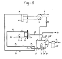
- boost pressure can be led through a branch pipe 42 directly to the actuator 231 of the gas pressure regulator 22.
- the boost pressure in the pipes 40, 41 and 42, controlled by the fuel pump with the integral governor 11, 12 provides the same function as the control signal in the connection 24 according to the Figures 1 and 2.
- the control lever 16 of the governor receives again an additional upper stop 28, 29 which acts in the same way as the upper stop according to Figure 1.
- an - not illustrated - in- and off-switchable throttling means may be applied in the fuel pipe 40 leaving the fuel pump governor and situated upstream of the branch pipe 42, which limits equally well the maximum diesel torque.
- the fuel boost pressure in the fuel injection pump is substantially proportional with the momentary diesel fuel consumption of the engine and thus can be applied as control signal 42 for the gas pressure regulator 20 as well.
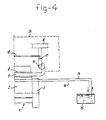
- Fig. 4 illustrates schematically an engine according to Fig. 1 or Fig. 2, provided with pressure charging by means of a compressor 91 driven by exhaust gas energy. It is incorporated in the air aspiration pipe or in the air-fuel-mixture suction pipe after the air filter 10 and possible other equipment and downstream of an eventual cooler.
- Said compressor 91 may consist of an exhaust gas driven turbine or form part of an exhaust gas- pressure wave transmitter, like a Comprex.
- the boost pressure produced generally is sufficiently proportional with the momentary consumed- diesel-fuel quantity, so that for the control signal 24 of the gas pressure regulator the charging pressure can be used directly (as illustrated) or indirectly.
Landscapes
- Engineering & Computer Science (AREA)
- Chemical & Material Sciences (AREA)
- Oil, Petroleum & Natural Gas (AREA)
- Combustion & Propulsion (AREA)
- Mechanical Engineering (AREA)
- General Engineering & Computer Science (AREA)
- Output Control And Ontrol Of Special Type Engine (AREA)
- Catalysts (AREA)
- Exhaust Gas After Treatment (AREA)
- High-Pressure Fuel Injection Pump Control (AREA)
Abstract
Description
- The invention relates to a system suitable for the use of gas as an additional fuel in a diesel engine of the high speed automotive type, having a substantially integral injection pump and speed governor unit having a fully enclosed fuel control rod for supplying diesel fuel, said system comprising:
- means for supplying gas in an amount to act as a secondary fuel;
- means including a mixing device for introducing said gas into aspirated combustion air;
- remotely adjustable stop means acting on the control rod of the fuel injection pump of said governor-pump unit for limiting the maximum injectable diesel fuel quantity to less than the full load pure diesel quantity responsive to the operation of the engine in the diesel/gas mode, and for permitting full load diesel fuel quantity to be supplied responsive to pure diesel operation;
- a pressure regulator means for regulating the gas pressure supplied from the gas supplying means to said mixing device;
- a means fitted in the gas supply line interrupting the flow of gas from the source.
- Such a system is basically known from the French patent application 2,206,444. From this publication it is known to feed gas as additional fuel to diesel engines. On the one hand this is done to economize the consumption of liquid diesel fuel and to consume gas as secondary fuel especially in case said gas is more readily available or even a waste product, on the other hand the system is also applied to improve the composition and the opacity of the exhaust gases in the full load range of the diesel engine. It is known that many diesel engines and especially older engines of older designs, operate at full load and sometimes even in a certain part of the speed range with maximum injection, near or even over an acceptable smoke limit. Apart from this, the requirements with regard to the smoke limit and the composition of the exhaust gases generally become more severe.
- Since the invention is concerned with diesel engines which use gas as additional fuel and thus liquid diesel fuel as main fuel, one consequently tries to keep the engine preferably unaltered and more specially to retain the existing compression ratio and the existing air swirl system in the cylinders. In order to operate the engine with different available gaseous secondary fuels sufficiently far from the detonation limit or the self- ignition limit in case of an engine at operation temperature, in general, dependent on the type of gas, no more than up to approximately 30% to 40% of the full load power should be provided by the gas and the remaining power by the standard diesel fuel. The control and/or the dimensioning of the metering means concerned for diesel fuel and forthe gas, should be accordingly adjusted or chosen. As far as the gas as secondary fuel is concerned, in the first place LPG will be considered, methane, belonging to the possible gases as well. Theoretically and also by experiment also other fuels are considered, which mix in gaseous or vapour form with the aspirated combustion air before entering the cylinder. Amongst them are alcohols or so.
- It is known that of all diesel engines the diesel fuel injection system and especially the fuel injection pump and the governor are highly qualified and sensitive apparatus. On the one hand they are sealed by the manufacturer in order to exclude over-load resulting from both the injected fuel quantity as the maximum speed, on the other hand they are fully dust-proof sealed and only the control lever of the governor extends. With most designs a small number of other extending knobs or levers exist, e.g. for extra fuel supply during a cold start, but these are reduced to a minimum and designed such that they are dust-proof and do not allow the user to disadjust the pump or governor.
- According to the above-mentioned French publication the control rod of the fuel injection pump is used to perform a control function and it is even subjected to external spring forces according to Figures 5 and 6 of said publication. In doing so the function of the governor can adversely be influenced, dust and other foreign matter can enter into the sensitive fuel injection pump resulting in malfunctioning and even worse. There is sufficient field experience that these important disadvantages should be overcome. The invention aims to provide a more reliable, simpler and better reproduceable control of diesel/gas-mixed operation, whereby as little as possible or preferably no alterations at all of the fuel injection system should be required. Only a small number of components to be fitted externally, preferably consisting of products available in the normal trade, should be used to rearrange the diesel engine for diesel/gas-mixed operation. Not only in last instance a system should be considered which is easy to retrofit in the field to existing engines. This does, of course, not exclude the possibility that also engines from new may be provided with the system according to the invention. A further important aim is to exclude possible overload of the engine. With a minimum of simple and reliable components this should be achieved.
- The system described in the preamble is according to the invention characterized in that
- the system further comprises a means for providing a control signal from a remote source, which control signal is at least substantially proportional to the momentary rate of diesel fuel consumption by the engine and which is fed to an actuator fitted to the gas pressure regulator means,
- whereby said pressure regulator means is responsive to said control signal thereby to regulate the quantity of gas supplied to said engine as a function of the momentary rate of diesel fuel consumption, and
- the interrupting means is fitted in the gas supply line upstream of the pressure regulator for shifting when shut said engine into pure diesel operation, wherein said stop means is simultaneously actuated with the interrupting means.
- Use is made of the well-known fact that the momentary load or torque provided by the engine is at least substantially proportional to the momentary rate of diesel fuel injected into the engine. By measuring said momentary rate of diesel fuel consumption on any moment and transducing it into a control signal for the actuator of the gas pressure regulator, the quantity of gas supplied to the engine can be controlled as function of the momentary rate of diesel fuel consumption at any moment. However, in order not to overload the engine by feeding it with both fuels, the earlier mentioned adjustable stop means acting on the control rod of the fuel injection pump should be actuated whenever the engine operates in the diesel/gas mode, to limit the maximum injectable diesel fuel quantity to less than the full load pure diesel quantity. This is combined with the control of the interrupting means for the gas supply to the engine so that the stop means for the diesel fuel is actuated simultaneously with the actuation of the interrupting means for the gas supply; according to the French publication the interrupting means for the gas supply is fitted directly upstream to the gas/air mixing device, which according to the French publication is a venturi. In contrast to this layout, the interrupting means for the gas supply is situated according to the invention upstream of the pressure regulator. It may be remarked that underneath, according to a preferred embodiment of the invention, a gas correction throttle valve will be discussed, which may be placed in the gas flow line on the same place as the interrupting means according to the French publication. However, said gas correction throttle valve serves a different purpose.
- The invented system should be applicable to as much as possible high speed automotive engines of different design. Amongst them two types of speed governors are used in great quantities. In case the governor is of the end-speed type, the system according to the invention is characterized in that the governor has a control lever, coupled directly to the control rod of the fuel injection pump for adjustment of the engine torque, and wherein said remotely adjustable stop means comprises a controllable upper stop acting on said control lever, which limits its maximum stroke of rotation to less than full load diesel position whenever the engine operates in the diesel/gas mode, and which permits the control lever to be rotatable to the full load position in pure diesel operation.
- Thanks to the fact that the position of the control lever is directly coupled to the control rod of the fuel injection pump, the remotely adjustable stop means can act directly on the control lever, avoiding any intervention into the inside of both the fuel pump or the governor.
- In case the engine is fitted with a governor of the all-speed type, fitted with a control lever for adjustment of the desired engine speed, the system according to the invention is characterized in that said stop means includes an upper stop acting on said control rod for limiting its maximum stroke to less than the full load diesel position whenever the engine operates in the diesel/gas mode, and which permits the rod to be movable to the full load position in pure diesel operation. Also in this case of an engine with an all-speed governor, no intervention in the governor has to take place, whereas at the fuel pump only an additional upper stop for the control rod has to be fitted, for which addition all well-known fuel injection pumps are already prepared by the manufacturer. This fitting location is generally the same place where for instance a boost pressure limiter or an extra starting fuel knob is or can be fitted. Thus, no intervention in the proper fuel injection pump is required with neither type of governor.
- The solution according to the invention is universal since it makes it possible to control the supplied gas quantity, independent of the load and the speed of the engine. The product of load times speed is known and equal to the effective quantity of diesel fuel consumed at each given moment. Thanks to the independency of the supplied gas quantity from load and speed, automatically the gas supply is reduced in the end control range near the maximum speed of the fuel pump by the governor, proportional with the reduction of the quantity of diesel fuel consumed on said very moment.
- The system is applicable for pumps of the Bosch-type built in line as well as of the rotating type. According to a preferred embodiment described underneath the system according to the invention is also applicable with fuel injection pump-governor combinations of the rotating type with hydraulic governor like the DPA of manufacturer CAV and the PT system of the US engine manufacturer Cummins.
- Because the gas pressure regulator is controlled by a control signal proportional to and derived from the measuring means of the diesel fuel consumption, the gas pressure regulator can deliver gas without requiring a subpressure or vacuum in the outgoing regulated gas pipe, as is the case with the known gas pressure regulator- evaporator combinations, which are used in great quantities for application with spark ignition engines. In doing so it is furthermore possible to avoid the additional installation of a venturi in the air aspiration manifold of the engine. A diesel engine, of course, does not require said venturi by itself and in a number of cases it will also be difficult to find an acceptable location for it. The fitting, however, of a simple gas mixing piece in the existing air aspiration manifold of the engine is sufficient and always easily possible.
- From experiments it was found that at a load of the engine of less than approximately 25%, gas, when supplied, would burn incompletely, which would have an adverse influence on both the total fuel consumption as on the composition of the exhaust gases. To avoid this in case of an engine fitted with an end-speed governor, a preferred embodiment is characterized in that the means for introducing said gas includes a gas line between said pressure regulator means and said mixing device, and comprising a gas correction throttle valve disposed in said gas line and means for connecting said throttle valve with said control lever for actuating said valve responsive to movement of said control lever, wherein said gas correction throttle valve is fully closed below a predetermined position of said lever and above said position gradually opens the passage between fully closed and fully open, whereby below a predetermined load the supply of gas is interrupted and said engine operates solely on diesel fuel.
- In case, however, the engine is fitted with an all-speed governor, according to a preferred embodiment the system is characterized in that the means for introducing said gas includes a gas line arranged between gas pressure regulator means and said mixing device, and comprising a gas correction throttle valve, and a rod system and an actuator for actuating said throttle valve; which rod system includes an equalizer having one end connected to the gas correction valve, its other end connected to said control lever of the governor and an intermediate pivot connected to said actuator; and means for controlling said actuator proportional to the value of said control signal for the pressure regulator means, wherein said valve is connected with said control lever and said actuator such that the gas correction throttle valve is fully closed below a predetermined engine load and above said load gradually opens the passage between fully closed and fully open, whereby below said predetermined load level the flow of gas is interrupted and said engine operates solely on diesel fuel.
- Said gas correction throttle valve is designed in such a way that, slightly dependent of the type and make of the engine, uner approximately 25% load, it keeps its passage closed and gradually opens its passage fully above said load when the load of the engine is increased. With small loads of the engines therefore little or no gas is consumed. In case of an engine with a governor of the all-speed type the position of the control rod in the fuel pump is fully and unknown and is in any case never directly coupled with the position of the control lever of the regulator. The coupling- back of the actually delivered engine power in this case takes place with the same signal which also controls the gas pressure, i.e. the signal derived from the measurement of the momentary diesel- fuel-consumption. The signal is coupled back through the equalizer over the actuator (like for instance a solenoid or a hydraulic cylinder) to the rod system forming the connection between the control lever of the regulator and the control lever of the gas correction throttle valve. With the aid of the equalizer the power delivered by the engine (diesel fuel consumption) is in a mechanical way divided by the engine speed (position of the control lever of the regulator), making available the engine torque provided by the diesel fuel. Thus its actioning is nearly equivalent to that with an engine provided with the simpler governor of the end speed type. It is emphasized that, from such engine load above approximately 25%, when the gas correction throttle valve is fully opened, the metering of the gas quantity is exclusively provided by the gas pressure regulator as function of the control signal derived from the measurement of the actually consumed diesel fuel.
- Also in case the engine on which the system according to the invention will be applied, it is fitted with pressure charging, the system is applicable without much ado, because the gas is supplied after the air filter and upstream of the pressure charging compressor. In doing so the supplied gas quantity remains a function of the momentary diesel fuel consumption and is thus by no means influenced by the eventual presence of a pressure charging compressor.
- According to a preferred embodiment the means for obtaining the control signal comprises a device for measuring the diesel fuel consumption which continuously measures the momentary difference between the flow from the diesel fuel tank to the engine and the return flow of the fuel to the tank. Said device for instance comprises a differential-vane pump with two rotors fitted to one shaft and a variable eccentricity of one of the rotor housings, which momentary eccentricity forms the control signal. However, other and reliable and in the field usable direct measuring means of the fuel flows are available, which can be applied with the invention and which are able to measure comparatively small fuel flows accurately without influencing on their turn the fuel system of the engine in an unacceptable way and which are nevertheless comparatively simple.
- When it is requested to prepare an engine for diesel/gas operation, which engine is provided with a diesel injection system in which the fuel boost pressure in the housing of the fuel pump is substantially proportional with the power by the engine, like for instance is the case with DPA pumps of the manufacturer CAV or with the PT system of the manufacturer Cummins, then it is advantageous to use for the control signal of the gas pressure regulator said boost pressure directly, which acts directly or indirectly through a connecting line on the regulator-diaphragm of the gas pressure regulator, all the above in such a way that with a higher boost pressure of the fuel a higher controlled gas pressure corresponds. When this system is used the measuring device for the diesel fuel consumption becomes superfluous. It will be evident that for the rest the operation of the system remains the same according to the invention.
- In case the engine is pressure-charged, the energy contained in the exhaust gases leaving the engine, given by its temperature, its pressure and its mass flow, is substantially proportional as well with the momentary fuel consumption. Its measuring, however, is almost impossible, but in case said energy flow is transformed by for instance an exhaust gas turbine and a compressor driven by it, then the resultant charging pressure is sufficiently proportional with said momentary fuel consumption. The same holds when a pressure-wave-compressor is used, like a Comprex made by the Swiss Brown Boveri Company (BBC), which uses as well the energy in the exhaust gases. As control signal for the gas pressure regulator, simply the charging pressure may be used either directly or indirectly.
- From the British Patent Specification GB-A-1,534,032 it is known to use the charging pressure in an exhaust pressure charged engine to control directly the gas supply valve upstream of the gas/ air mixing device. In contrast to the British design, according to the present application the charging pressure is directly used as control signal acting on the gas pressure regulator. The gas pressure regulator used according to the British publication is not influenced or controlled by the charging pressure.
- Finally it may be pointed out that, in case LPG is used as secondary gaseous fuel, a normal in the trade available pressure regulator can be used, which generally is already combined with the necessary evaporator. These pressure regulators generally allow passage of vaporized LPG only in case in the outlet line to the gas mixing device a subpressure or vacuum prevails. In case of spark ignition engines this subpressure is provided by a venturi. In case of the present invention said venturi and the subpressure provided by it are not necessary, since the diaphragm of the pressure regulator is under the influence of the actuator, which receives the control signal which is a function of the momentary diesel fuel consumption. Therefore a normally in the trade available vaporizer-pressure regulator can be used, which only needs to be supplemented with the actuator which reacts on said control signal. For this purpose a solenoid or a hydraulic cylinder can be used, depending on whether the control signal is an electric or a hydraulic one.
- The U.S. Patent Specification 4,278,064 describes a classic constant speed dual fuel engine which basically is controlled in such a way that as much gas as is available will be consumed, the liquid fuel injection being reduced to the minimum possible, being the pilot injection. This pilot injection ranges between 5% and 15% of the full load diesel consumption. Only in case of lack of sufficient gas, this lack is balanced by injecting more liquid fuel. In conformity with most of the larger classic dual fuel engines, a separate speed governor is used, having an open and accessible linking structure with the fuel injection pumps. Its control forces are generally at least tenfold of those used in the governor-pump unit of high speed automotive engines. Load measurements derived from the fuel pump rods can easily be made in different ways with this type of engines.
- With the aid of the following description of the figures preferred embodiments according to the invention will be explained more in detail.
- Figure 1 illustrates schematically an engine with the system for diesel-gas operation according to the invention, fitted to a diesel engine provided with a governor of the end speed type;
- Figure 2 illustrates the same engine and the same system as Figure 1, but applied to an engine provided with an all speed governor;
- Figure 3 illustrates schematically the system according to the invention, applied to an engine with a fuel pump-governor system in which the fuel boost pressure is substantially proportional to the power supplied by the engine, more specially the Cummins PT system;
- Figure 4 illustrates the right part of Figures 1 or 2, in which the engine is provided with a schematically indicated pressure charging compressor, driven by the exhaust gases flowing through a turbine or a pressure wave compressor (Comprex).
- In the three figures corresponding parts are indicated with the same references, whilst parts with the same function but differently executed are indicated with the same reference followed by the
numeral 1. - With reference 1 a diesel engine of the automotive type is indicated. The crank case and cylinder block form as usual one
integral part 2. At the rear side a flywheel withbell housing 3 are fitted, the lower side of the crank case being closed by anoil sump 4. At the front side of the engine, driven by a not illustrated crank shaft, there is anauxiliary drive system 5, which between others drives afan 6 for the cooling of the engine cooling fluid in aradiator 7. With thesame drive 5 other, not further illustrated, auxiliaries can be driven. On thecylinder block 2 one ormore cylinder heads 8 are fitted, closed at their upper side by valve covers 81. Along the visible side in Figure 1 of the engine runs along thecylinder heads 8 theair inlet manifold 9, through which the engine aspirates its combustion air through anair filter 10. The engine is provided with a schematically indicated dieselfuel injection pump 11, which as usual is provided with anintegral governor 12. Not indicated is the drive of the fuel pump and the governor, but it will be clear for an expert that this is done in the usual way proportional to the speed of the crank shaft. The usual injectors and fuel injection lines are not indicated as well. Through afuel supply line 13 diesel fuel is fed to the injection pump from atank 15, the surplus fuel together with eventual leak fuel from the injectors being returned to thetank 15 as usual through thereturn line 14. On thegovernor 12 thenormal control lever 16 is fitted. Thegovernor 12, as indicated in Figure 1, is of the end speed type, so taht with thecontrol lever 16 the control rod of the fuel injection pump is directly adjusted and thus the torque supplied by the engine. With the above description the normal parts belonging to a diesel engine are described as far as they are of interest for the present invention. - To adapt the engine for diesel-gas-mixed operation first a
gas mixing device 17 has to be installed in the air intake manifold. Through aline 18, in which a gascorrection throttle valve 19 is incorporated, gas is fed to the engine from agas pressure regulator 20. Said regulator contains as usual a non-illustrated control diaphragm and can, in case LPG is used as secondary fuel, furthermore be provided with a not further detailed evaporator. The gas, for instance LPG, is supplied through aline 21 to thepressure regulator 20, in which line a remoteoperable valve 22 is installed, which line 21 supplies the secondary fuel in fluid or gaseous form from a not illustratedsource 211. The gas pressure prevailing inline 18 connected to the outlet of thepressure regulator 20 and the resulting gas flow are controlled by anactuator 23, which receives a control signal through aconnection 24. Saidcontrol signal 24 may be electric or hydraulic, in which case theactuator 23 may consist of a solenoid respectively a hydraulic-piston cylinder combination. Both provide a force on the diaphragm of thegas pressure regulator 20, proportional with the value of thecontrol signal 24. Saidcontrol signal 24 is produced by ameans 25 which measures the actual consumed quantity of diesel fuel as difference between the fuel flow throughline 13 from thetank 15 and return flow through theline 14. The signal produced by the measuring means 25 for the consumption of diesel fuel can for instance be electric or hydraulic. - The gas
correction throttle valve 19 is provided with a control.lever 26 which by means of arod system 27 is mechanically coupled with thecontrol lever 16 of thegovernor 12. The operation of the gas correction throttle valve is such that up to a predetermined position of for instance approximately 25% load, thevalve 19 remains fully closed, but above said position the passage gradually opens between the fully closed and fully opened position. Therefore the quantity of gas supplied to the engine above said predetermined value of for instance approximately 25% power, soon is controlled exclusively by thesignal 24 which is proportional with the momentary actual diesel fuel consumption by the engine. In service therefore whenever theend governor 12 retracts the diesel fuel control rod in case the engine speed surpasses the maximum, the gas quantity supplied is also reduced since the diesel fuel consumption is reduced. - In order to avoid an overload of the engine by the supply of gas apart from an uncontrolled supply of diesel fuel, an externally fitted
upper stop control lever 16 of thegovernor 12 is provided. Said upper stop is remotely actuable and may consist of asolenoid 28 with astop 29. When actuating the solenoid thestop 29 forms an extra stop for thecontrol lever 16, limiting its stroke to e.g. a maximum of 75% of the full load diesel power. By energizing simultaneously the gas supply valve 22 a proportional quantity of gas will be supplied to the engine, the calibration of the gas supply system being such that the remaining forinstance 25% of the power will be supplied by the gas, so that the engine again is able to deliver its rated power for the full 100%. Is subsequently the extraupper stop 28 deactivated, thestop 29 retracting and thecontrol lever 16 becoming adjustable again to the full 100%, the diesel engine may also be loaded for the full 100% in the diesel mode, and by simultaneously de-energizing thevalve 22 the gas supply will be fully interrupted. It will be evident that the values mentioned above of 75% and 25% are only examples, but in connection with the relatively high compression ratio of a diesel engine compared to a spark ignition engine, in general and in practice gas can only be supplied up to a maximum of about 40% in order to avoid detonation. The remaining power will remain to be supplied by the liquid diesel fuel. - For the
means 25 capable to measure the diesel fuel consumption, in trade available measuring means are applicable, like e.g. a differential vane pump with two rotors on one single shaft and a variable excentricity of one of the rotor housings, whereby the excentricity on each moment provides thecontrol signal 24 by converting it into for instance a hydraulic or electric signal. - In Figure 2 the same engine is depicted as in Figure 1 fitted with the same gas installation, but fitted with a
different governor 12 to thediesel injection pump 11, being in this case of the all speed type. Independent of the position of thecontrol lever 16 the control rod in the fuel pump may take any position between full load and zero load, because with such a governor only a certain speed of the engine is adjusted with thecontrol lever 16 and the governor answers said adjustment by controlling the control rod in order to supply the unknown torque requirements in order to have the engine drive the load at the adjusted speed. A limitation of the maximum diesel fuel to be injected can therefore not take place through thecontrol lever 16, but it should take place on the control rod of the fuel pump itself. Therefore, the extraupper stop correction throttle valve 19 and thecontrol lever 16 of thegovernor 12 are executed such that the actual momentary diesel fuel consumption is introduced as variable value as well. For this purpose abranch 241 is made to thecontrol signal connection 24, which acts on anactuator 34 with an extending actuator rod 35 at the end of which an equalizer 30 is pivotably fitted in a point 33. The one end of the equalizer is connected through arod 32 with acontrol lever 26 of the gascorrection throttle valve 19, whilst the other end of the equalizer 30 is connected through a rod 31 with thecontrol lever 16 of theengine governor 12. In Figure 2 theactuator 34 is schematically depicted in a design corresponding to the case in which the control signal in theconnection 241 is a hydraulic one, in which case a piston is able to move the pivot 33 of the equalizer higher or lower against the force of a spring. In doing so a coupling back of the engine power provided is possible through the actually consumed diesel fuel quantity, so that on the one hand overload of the engine and on the other hand overspeed both are impossible. The characteristic of the engine also in the diesel-gas mode, is substantially the same as the characteristic of the engine according to Figure 1 thanks to the above described lay-out. - In Figure 3 the engine itself is not illustrated for clarity reasons. An engine with pressure-charging
compressor 91 is concerned, which is fitted after thegas mixing device 17 in theinlet manifold 9. Below only the differences with the executions according to Figures 1 and 2 will be described. In Figure 3 the system is depicted as applicable to a Cummins engine with PT-diesel injection system. The fuel injection pump with governor 11-12 again forms a unit, but there are with this system no separate high pressure injection pipes for each individual cylinder. On the contrary, there extends acommon pipe 40, 41 passing and connected to all injectors of the engine. In saidpipe 40, 41 prevails a boost pressure of several bar, which is substantially proportional to the momentary diesel fuel consumption of the engine. Therefore said boost pressure can be led through abranch pipe 42 directly to theactuator 231 of thegas pressure regulator 22. The boost pressure in thepipes integral governor connection 24 according to the Figures 1 and 2. Thecontrol lever 16 of the governor receives again an additionalupper stop upper stop branch pipe 42, which limits equally well the maximum diesel torque. - Also in case an injection system of the CAV/DPA type is used, the fuel boost pressure in the fuel injection pump is substantially proportional with the momentary diesel fuel consumption of the engine and thus can be applied as
control signal 42 for thegas pressure regulator 20 as well. - Fig. 4 illustrates schematically an engine according to Fig. 1 or Fig. 2, provided with pressure charging by means of a
compressor 91 driven by exhaust gas energy. It is incorporated in the air aspiration pipe or in the air-fuel-mixture suction pipe after theair filter 10 and possible other equipment and downstream of an eventual cooler. - Said
compressor 91 may consist of an exhaust gas driven turbine or form part of an exhaust gas- pressure wave transmitter, like a Comprex. The boost pressure produced generally is sufficiently proportional with the momentary consumed- diesel-fuel quantity, so that for thecontrol signal 24 of the gas pressure regulator the charging pressure can be used directly (as illustrated) or indirectly.
Claims (9)
Priority Applications (1)
| Application Number | Priority Date | Filing Date | Title |
|---|---|---|---|
| AT83201183T ATE34015T1 (en) | 1982-08-12 | 1983-08-10 | DEVICE FOR SUPPLYING GAS AS SECONDARY FUEL FOR DIESEL ENGINES. |
Applications Claiming Priority (2)
| Application Number | Priority Date | Filing Date | Title |
|---|---|---|---|
| NL8203169 | 1982-08-12 | ||
| NL8203169A NL8203169A (en) | 1982-08-12 | 1982-08-12 | SYSTEM FOR USING GAS AS A SECOND FUEL IN DIESEL ENGINES. |
Publications (2)
| Publication Number | Publication Date |
|---|---|
| EP0102119A1 EP0102119A1 (en) | 1984-03-07 |
| EP0102119B1 true EP0102119B1 (en) | 1988-05-04 |
Family
ID=19840128
Family Applications (1)
| Application Number | Title | Priority Date | Filing Date |
|---|---|---|---|
| EP83201183A Expired EP0102119B1 (en) | 1982-08-12 | 1983-08-10 | system for the use of gas as secondary fuel in diesel engines |
Country Status (12)
| Country | Link |
|---|---|
| US (1) | US4517928A (en) |
| EP (1) | EP0102119B1 (en) |
| JP (1) | JPS5949344A (en) |
| AT (1) | ATE34015T1 (en) |
| AU (1) | AU548811B2 (en) |
| BR (1) | BR8304334A (en) |
| CA (1) | CA1213484A (en) |
| DE (1) | DE3376492D1 (en) |
| IN (1) | IN161555B (en) |
| NL (1) | NL8203169A (en) |
| SU (1) | SU1613001A3 (en) |
| ZA (1) | ZA835922B (en) |
Cited By (1)
| Publication number | Priority date | Publication date | Assignee | Title |
|---|---|---|---|---|
| US6095101A (en) * | 1997-01-29 | 2000-08-01 | Man B&W Diesel A/S | Internal combustion engine of the diesel type for combustion of gas, and a method of supplying such an engine with fuel |
Families Citing this family (34)
| Publication number | Priority date | Publication date | Assignee | Title |
|---|---|---|---|---|
| NZ205140A (en) * | 1983-08-04 | 1987-02-20 | H M Reid | Electronically controlled dual fuel system for diesel engines |
| US4505249A (en) * | 1984-04-30 | 1985-03-19 | Emco Wheaton International Limited | Fuel control system for gaseous fueled engines |
| GB8425577D0 (en) * | 1984-10-10 | 1984-11-14 | Flintheath Ltd | Fuel control system |
| GB8521244D0 (en) * | 1985-08-24 | 1985-10-02 | Gas Power International Ltd | Dual fuel compression ignition engine |
| US4953515A (en) * | 1988-11-28 | 1990-09-04 | Fehr William A | Diesel engine secondary fuel injection system |
| AU644255B2 (en) * | 1990-12-17 | 1993-12-02 | Allgas Energy Limited | Control system for diesel engines |
| US5224457A (en) * | 1992-02-28 | 1993-07-06 | Deere & Company | Dual fuel electronic control system |
| US5355854A (en) * | 1993-03-12 | 1994-10-18 | Aubee Thomas A | Supplemental gaseous fuel system for a diesel engine |
| AUPM632494A0 (en) * | 1994-06-21 | 1994-07-14 | Biocom Pty Ltd | Auxiliary injector |
| DK173242B1 (en) * | 1997-01-29 | 2000-05-22 | Man B&W Diesel A/S | of such a gas engine and a method of fuel supply Diesel-type combustion engine for combustion |
| AU727897B2 (en) * | 1997-06-30 | 2001-01-04 | Gregory Rex Bailey | A dual-fuel method for boost fuel substitution in turbo-charged diesel engines |
| AUPO763497A0 (en) * | 1997-06-30 | 1997-07-24 | Bailey, Gregory Rex | A dual-fuel method for boost fuel substitution in turbo-charged diesel engines |
| RU2137937C1 (en) * | 1998-03-03 | 1999-09-20 | Челябинский государственный технический университет | Method of and device for feeding and metering of fuel in gas diesel engine |
| US6101986A (en) * | 1998-03-06 | 2000-08-15 | Caterpillar Inc. | Method for a controlled transition between operating modes of a dual fuel engine |
| NL1015485C2 (en) * | 2000-06-21 | 2001-12-28 | Petrocare B V | Tanker ship, has sealable pipe extending between hold and engine inlet |
| EP1546532B1 (en) * | 2002-09-24 | 2009-11-11 | Engine Control Technology, LLC | Methods and apparatus for operation of multiple fuel engines |
| US6863034B2 (en) * | 2003-01-17 | 2005-03-08 | Robert D. Kern | Method of controlling a bi-fuel generator set |
| US7019626B1 (en) | 2005-03-03 | 2006-03-28 | Omnitek Engineering, Inc. | Multi-fuel engine conversion system and method |
| US7591253B2 (en) | 2006-07-28 | 2009-09-22 | Proinjects, L.L.C. | Secondary fuel system for diesel engines |
| DE102007017561A1 (en) | 2007-04-12 | 2008-10-16 | Cornelis Hendrik Heim | Diesel fuel and combustible gas common combustion method for combustion chamber of vehicle's diesel engine, involves merging combustible gas and charge air to fuel air mixture that is compressed |
| JP2012515284A (en) * | 2009-01-12 | 2012-07-05 | ガス テック ソリューションズ プロプライエタリー リミテッド | Sensor output correction device |
| DE102010033461B4 (en) * | 2010-08-05 | 2012-07-26 | Ttg Truck Technologie Gmbh | Fuel system, use of a retrofit kit and method for operating an engine with the fuel system |
| GB2488814A (en) * | 2011-03-09 | 2012-09-12 | Mobilizer Ltd | Engine Performance Modification or Tuning Kit |
| NL2006542C2 (en) * | 2011-04-05 | 2012-10-08 | Vialle Alternative Fuel Systems Bv | DIESEL ENGINE FOR LPG-DIESEL-MIXTURE. |
| DE102011082039A1 (en) * | 2011-09-02 | 2013-03-07 | Man Diesel & Turbo Se | Reciprocating internal combustion engine and method for operating a reciprocating internal combustion engine |
| WO2015130272A1 (en) * | 2014-02-26 | 2015-09-03 | Halliburton Energy Services, Inc. | Optimizing diesel fuel consumption for dual-fuel engines |
| US9546941B2 (en) * | 2015-05-04 | 2017-01-17 | Caterpillar Inc. | Method and system for estimating the specific gravity of an unknown fuel source in a multi-fuel engine |
| RU177583U1 (en) * | 2016-04-26 | 2018-03-01 | федеральное государственное бюджетное образовательное учреждение высшего образования "Пензенский государственный аграрный университет" | Device for dosed supply of activator to diesel |
| RU2633337C1 (en) * | 2016-04-29 | 2017-10-11 | Федеральное государственное бюджетное образовательное учреждение высшего образования "Вятский государственный университет" | Electronic system for feeding gas fuel to supercharged diesel engine and cooling supercharging air |
| IT201800009121A1 (en) * | 2018-10-03 | 2020-04-03 | Ecopower Hg Srl | SYSTEM FOR THE CONVERSION OF A DIESEL ENGINE INTO A DUAL-FUEL ENGINE |
| CN112696299A (en) * | 2019-10-23 | 2021-04-23 | 罗伯特·博世有限公司 | Method for determining the amount of fuel flowing in a return passage of a fuel injector |
| CN113494364B (en) * | 2021-07-27 | 2022-07-29 | 达魔重卡电动汽车制造(杭州)有限公司 | Closed-loop control module for gas fuel supply system of turbine engine |
| CN113443807B (en) * | 2021-08-30 | 2021-11-19 | 天津市星拓科技发展有限公司 | High-pressure sealed filter plate unit structure and using method |
| US11767811B2 (en) * | 2021-09-01 | 2023-09-26 | American CNG, LLC | Supplemental fuel system for compression-ignition engine |
Citations (2)
| Publication number | Priority date | Publication date | Assignee | Title |
|---|---|---|---|---|
| GB1415252A (en) * | 1972-01-14 | 1975-11-26 | Snam Progetti | Equipment for and method of operating diesel engines with gas oil and petroleum gas |
| GB1534032A (en) * | 1975-02-07 | 1978-11-29 | Landi Den Hartog Bv | Supercharged dual fuel ic engine and control device therefor |
Family Cites Families (11)
| Publication number | Priority date | Publication date | Assignee | Title |
|---|---|---|---|---|
| US2400247A (en) * | 1945-03-14 | 1946-05-14 | Worthington Pump & Mach Corp | Internal-combustion engine |
| US2544978A (en) * | 1949-01-18 | 1951-03-13 | Worthington Pump & Mach Corp | Multiple fuel internal-combustion engine |
| US2558884A (en) * | 1949-12-15 | 1951-07-03 | Worthington Pump & Mach Corp | Temperature controlled air throttling apparatus and method for controlling supply ofair to internal-combustion engines |
| US2908258A (en) * | 1956-06-13 | 1959-10-13 | Fairbanks Morse & Co | Fuel control mechanism for diesel engines |
| CH483562A (en) * | 1967-11-10 | 1969-12-31 | Sulzer Ag | Method for introducing fuel into the working cylinder of a multi-cylinder piston internal combustion engine and device for carrying out the method |
| CH535376A (en) * | 1971-03-10 | 1973-03-31 | Sulzer Ag | Power plant with a diesel internal combustion engine for operation with liquid fuel and with gas |
| GB1370619A (en) * | 1971-12-15 | 1974-10-30 | Exxon Research Engineering Co | Operation of compression-ignition engines |
| BE793932A (en) * | 1972-01-14 | 1973-05-02 | Snam Progetti | SYSTEM AND EQUIPMENT FOR THE MIXED SUPPLY OF GAS OIL AND LIQUEFIED PETROLEUM GAS FOR DIESEL ENGINES |
| AU6214373A (en) * | 1972-11-10 | 1975-05-08 | Calor Gas Ltd | Fuel supply control systems for diesel engines |
| US4278064A (en) * | 1979-03-07 | 1981-07-14 | Deere & Company | Fuel control system for a dual-fueled power unit |
| US4463734A (en) * | 1982-05-14 | 1984-08-07 | Akeroyd Richard T | Dual fuel diesel engine |
-
1982
- 1982-08-12 NL NL8203169A patent/NL8203169A/en not_active Application Discontinuation
-
1983
- 1983-08-02 US US06/519,562 patent/US4517928A/en not_active Expired - Fee Related
- 1983-08-10 EP EP83201183A patent/EP0102119B1/en not_active Expired
- 1983-08-10 DE DE8383201183T patent/DE3376492D1/en not_active Expired
- 1983-08-10 AT AT83201183T patent/ATE34015T1/en not_active IP Right Cessation
- 1983-08-10 CA CA000434250A patent/CA1213484A/en not_active Expired
- 1983-08-11 SU SU833632199A patent/SU1613001A3/en active
- 1983-08-11 JP JP58145818A patent/JPS5949344A/en active Pending
- 1983-08-11 AU AU17878/83A patent/AU548811B2/en not_active Ceased
- 1983-08-11 ZA ZA835922A patent/ZA835922B/en unknown
- 1983-08-11 BR BR8304334A patent/BR8304334A/en unknown
- 1983-08-12 IN IN1003/CAL/83A patent/IN161555B/en unknown
Patent Citations (2)
| Publication number | Priority date | Publication date | Assignee | Title |
|---|---|---|---|---|
| GB1415252A (en) * | 1972-01-14 | 1975-11-26 | Snam Progetti | Equipment for and method of operating diesel engines with gas oil and petroleum gas |
| GB1534032A (en) * | 1975-02-07 | 1978-11-29 | Landi Den Hartog Bv | Supercharged dual fuel ic engine and control device therefor |
Cited By (1)
| Publication number | Priority date | Publication date | Assignee | Title |
|---|---|---|---|---|
| US6095101A (en) * | 1997-01-29 | 2000-08-01 | Man B&W Diesel A/S | Internal combustion engine of the diesel type for combustion of gas, and a method of supplying such an engine with fuel |
Also Published As
| Publication number | Publication date |
|---|---|
| US4517928A (en) | 1985-05-21 |
| ZA835922B (en) | 1984-04-25 |
| AU548811B2 (en) | 1986-01-02 |
| CA1213484A (en) | 1986-11-04 |
| JPS5949344A (en) | 1984-03-21 |
| SU1613001A3 (en) | 1990-12-07 |
| AU1787883A (en) | 1984-02-16 |
| BR8304334A (en) | 1984-03-20 |
| IN161555B (en) | 1987-12-26 |
| ATE34015T1 (en) | 1988-05-15 |
| NL8203169A (en) | 1984-03-01 |
| EP0102119A1 (en) | 1984-03-07 |
| DE3376492D1 (en) | 1988-06-09 |
Similar Documents
| Publication | Publication Date | Title |
|---|---|---|
| US4517928A (en) | System for the use of gas as secondary fuel in diesel engines | |
| CA1231415A (en) | Dual fuel control and supply system for internal combustion engines | |
| US4299090A (en) | Internal combustion engine with at least two exhaust gas turbochargers | |
| US4541397A (en) | Gaseous fuel carburetion system | |
| EP0064373A1 (en) | Gaseous fuel carburetion | |
| JPS63501088A (en) | Dual fuel compression ignition engine | |
| CA2145053A1 (en) | Dual fuel system | |
| US4626170A (en) | Propulsion aggregate for an aircraft | |
| EP1243776B1 (en) | Combined control of dual fuel system for diesel cycle engines | |
| EP0195803B1 (en) | Supplemental fueling of compression ignition engines | |
| JPH07243332A (en) | Method and equipment for governing internal combustion engine | |
| US4354476A (en) | Apparatus for controlling the recirculated exhaust gas quantities and the injection quantity in auto-igniting internal combustion engines | |
| JP4319481B2 (en) | Fuel gas supply and supply system for lean combustion gas engines | |
| US4474161A (en) | Method for mixture formation for mixture-compressing internal combustion engines and fuel supply system for performing the method | |
| GB2031996A (en) | Fuel injection system | |
| US4459964A (en) | Fuel supply apparatus for internal combustion engines | |
| US4193384A (en) | Fuel injection system | |
| US4391252A (en) | Fuel injection system | |
| WO1999001659A1 (en) | A dual-fuel method for boost fuel substitution in turbo-charged diesel engines | |
| EP0044743A1 (en) | A Diesel/gas engine conversion means | |
| US4161933A (en) | Mixture control apparatus for internal combustion engines | |
| RU2137937C1 (en) | Method of and device for feeding and metering of fuel in gas diesel engine | |
| US2795107A (en) | Torque-responsive control systems for controlling the supply of fluids to combustion engines | |
| US3611721A (en) | Fuel control system for gas turbine engines | |
| CN108180088A (en) | Metering units for the internal combustion engine run by fuel gas |
Legal Events
| Date | Code | Title | Description |
|---|---|---|---|
| PUAI | Public reference made under article 153(3) epc to a published international application that has entered the european phase |
Free format text: ORIGINAL CODE: 0009012 |
|
| AK | Designated contracting states |
Designated state(s): AT BE CH DE FR GB IT LI LU NL SE |
|
| 17P | Request for examination filed |
Effective date: 19840820 |
|
| GRAA | (expected) grant |
Free format text: ORIGINAL CODE: 0009210 |
|
| AK | Designated contracting states |
Kind code of ref document: B1 Designated state(s): AT BE CH DE FR GB IT LI LU NL SE |
|
| REF | Corresponds to: |
Ref document number: 34015 Country of ref document: AT Date of ref document: 19880515 Kind code of ref document: T |
|
| ITF | It: translation for a ep patent filed | ||
| REF | Corresponds to: |
Ref document number: 3376492 Country of ref document: DE Date of ref document: 19880609 |
|
| ET | Fr: translation filed | ||
| PG25 | Lapsed in a contracting state [announced via postgrant information from national office to epo] |
Ref country code: LU Free format text: LAPSE BECAUSE OF NON-PAYMENT OF DUE FEES Effective date: 19880831 |
|
| PLBE | No opposition filed within time limit |
Free format text: ORIGINAL CODE: 0009261 |
|
| STAA | Information on the status of an ep patent application or granted ep patent |
Free format text: STATUS: NO OPPOSITION FILED WITHIN TIME LIMIT |
|
| 26N | No opposition filed | ||
| PG25 | Lapsed in a contracting state [announced via postgrant information from national office to epo] |
Ref country code: GB Effective date: 19890810 Ref country code: AT Effective date: 19890810 |
|
| PG25 | Lapsed in a contracting state [announced via postgrant information from national office to epo] |
Ref country code: SE Effective date: 19890811 |
|
| PG25 | Lapsed in a contracting state [announced via postgrant information from national office to epo] |
Ref country code: LI Effective date: 19890831 Ref country code: CH Effective date: 19890831 Ref country code: BE Effective date: 19890831 |
|
| BERE | Be: lapsed |
Owner name: NEDERLANDSE CENTRALE ORGANISATIE VOOR TOEGEPAST-N Effective date: 19890831 |
|
| PG25 | Lapsed in a contracting state [announced via postgrant information from national office to epo] |
Ref country code: NL Effective date: 19900301 |
|
| GBPC | Gb: european patent ceased through non-payment of renewal fee | ||
| NLV4 | Nl: lapsed or anulled due to non-payment of the annual fee | ||
| PG25 | Lapsed in a contracting state [announced via postgrant information from national office to epo] |
Ref country code: FR Effective date: 19900427 |
|
| REG | Reference to a national code |
Ref country code: CH Ref legal event code: PL |
|
| PG25 | Lapsed in a contracting state [announced via postgrant information from national office to epo] |
Ref country code: DE Effective date: 19900501 |
|
| REG | Reference to a national code |
Ref country code: FR Ref legal event code: ST |
|
| EUG | Se: european patent has lapsed |
Ref document number: 83201183.7 Effective date: 19900418 |