EP0101572B1 - Positive selection sorting of cells - Google Patents
Positive selection sorting of cells Download PDFInfo
- Publication number
- EP0101572B1 EP0101572B1 EP83107289A EP83107289A EP0101572B1 EP 0101572 B1 EP0101572 B1 EP 0101572B1 EP 83107289 A EP83107289 A EP 83107289A EP 83107289 A EP83107289 A EP 83107289A EP 0101572 B1 EP0101572 B1 EP 0101572B1
- Authority
- EP
- European Patent Office
- Prior art keywords
- cells
- cell
- plate
- microscope
- wanted
- Prior art date
- Legal status (The legal status is an assumption and is not a legal conclusion. Google has not performed a legal analysis and makes no representation as to the accuracy of the status listed.)
- Expired
Links
- 238000000034 method Methods 0.000 claims description 28
- 238000001514 detection method Methods 0.000 claims description 18
- 238000004020 luminiscence type Methods 0.000 claims description 12
- XKRFYHLGVUSROY-UHFFFAOYSA-N Argon Chemical compound [Ar] XKRFYHLGVUSROY-UHFFFAOYSA-N 0.000 claims description 8
- 230000008569 process Effects 0.000 claims description 8
- 230000002238 attenuated effect Effects 0.000 claims description 7
- 239000007789 gas Substances 0.000 claims description 7
- 239000001963 growth medium Substances 0.000 claims description 7
- 239000000126 substance Substances 0.000 claims description 7
- 230000000704 physical effect Effects 0.000 claims description 5
- 230000005855 radiation Effects 0.000 claims description 5
- 229910052786 argon Inorganic materials 0.000 claims description 4
- 230000007613 environmental effect Effects 0.000 claims description 3
- 239000000203 mixture Substances 0.000 claims description 3
- 238000012544 monitoring process Methods 0.000 claims description 3
- 230000004044 response Effects 0.000 claims description 3
- 239000012530 fluid Substances 0.000 claims description 2
- 239000007788 liquid Substances 0.000 claims 3
- 230000003993 interaction Effects 0.000 claims 2
- 239000002985 plastic film Substances 0.000 claims 2
- 229920006255 plastic film Polymers 0.000 claims 2
- 230000001419 dependent effect Effects 0.000 claims 1
- 230000004298 light response Effects 0.000 claims 1
- 210000004027 cell Anatomy 0.000 description 111
- 239000010408 film Substances 0.000 description 20
- 230000006870 function Effects 0.000 description 7
- 230000001413 cellular effect Effects 0.000 description 6
- 239000012528 membrane Substances 0.000 description 6
- 230000006378 damage Effects 0.000 description 5
- 238000005259 measurement Methods 0.000 description 5
- 238000004458 analytical method Methods 0.000 description 4
- 230000008901 benefit Effects 0.000 description 4
- 238000002955 isolation Methods 0.000 description 4
- 239000000523 sample Substances 0.000 description 4
- 238000000926 separation method Methods 0.000 description 4
- 102000004856 Lectins Human genes 0.000 description 3
- 108090001090 Lectins Proteins 0.000 description 3
- 238000013459 approach Methods 0.000 description 3
- 238000012512 characterization method Methods 0.000 description 3
- 238000010586 diagram Methods 0.000 description 3
- 238000009792 diffusion process Methods 0.000 description 3
- 239000000975 dye Substances 0.000 description 3
- 230000000694 effects Effects 0.000 description 3
- 239000002523 lectin Substances 0.000 description 3
- 239000003550 marker Substances 0.000 description 3
- 230000036962 time dependent Effects 0.000 description 3
- CURLTUGMZLYLDI-UHFFFAOYSA-N Carbon dioxide Chemical compound O=C=O CURLTUGMZLYLDI-UHFFFAOYSA-N 0.000 description 2
- 206010028980 Neoplasm Diseases 0.000 description 2
- 230000004075 alteration Effects 0.000 description 2
- 230000024245 cell differentiation Effects 0.000 description 2
- 230000022534 cell killing Effects 0.000 description 2
- 238000005516 engineering process Methods 0.000 description 2
- 238000002474 experimental method Methods 0.000 description 2
- 239000011521 glass Substances 0.000 description 2
- 230000012010 growth Effects 0.000 description 2
- 230000006698 induction Effects 0.000 description 2
- 238000011835 investigation Methods 0.000 description 2
- 230000007774 longterm Effects 0.000 description 2
- 238000012423 maintenance Methods 0.000 description 2
- 239000002609 medium Substances 0.000 description 2
- 238000002156 mixing Methods 0.000 description 2
- 238000012545 processing Methods 0.000 description 2
- 238000000746 purification Methods 0.000 description 2
- 239000010409 thin film Substances 0.000 description 2
- 208000023275 Autoimmune disease Diseases 0.000 description 1
- 208000035473 Communicable disease Diseases 0.000 description 1
- 102000004190 Enzymes Human genes 0.000 description 1
- 108090000790 Enzymes Proteins 0.000 description 1
- 208000026350 Inborn Genetic disease Diseases 0.000 description 1
- 206010025323 Lymphomas Diseases 0.000 description 1
- 108010052285 Membrane Proteins Proteins 0.000 description 1
- 210000001744 T-lymphocyte Anatomy 0.000 description 1
- 238000002679 ablation Methods 0.000 description 1
- 239000011358 absorbing material Substances 0.000 description 1
- 239000000654 additive Substances 0.000 description 1
- 239000000853 adhesive Substances 0.000 description 1
- 230000001070 adhesive effect Effects 0.000 description 1
- 230000006907 apoptotic process Effects 0.000 description 1
- WZSUOQDIYKMPMT-UHFFFAOYSA-N argon krypton Chemical compound [Ar].[Kr] WZSUOQDIYKMPMT-UHFFFAOYSA-N 0.000 description 1
- QVGXLLKOCUKJST-UHFFFAOYSA-N atomic oxygen Chemical compound [O] QVGXLLKOCUKJST-UHFFFAOYSA-N 0.000 description 1
- 230000004888 barrier function Effects 0.000 description 1
- 230000003542 behavioural effect Effects 0.000 description 1
- 238000012742 biochemical analysis Methods 0.000 description 1
- 238000004061 bleaching Methods 0.000 description 1
- 201000011510 cancer Diseases 0.000 description 1
- 239000001569 carbon dioxide Substances 0.000 description 1
- 229910002092 carbon dioxide Inorganic materials 0.000 description 1
- 230000022131 cell cycle Effects 0.000 description 1
- 230000030833 cell death Effects 0.000 description 1
- 230000010261 cell growth Effects 0.000 description 1
- 210000000170 cell membrane Anatomy 0.000 description 1
- 230000003833 cell viability Effects 0.000 description 1
- 230000036755 cellular response Effects 0.000 description 1
- 230000008859 change Effects 0.000 description 1
- 230000001427 coherent effect Effects 0.000 description 1
- 150000001875 compounds Chemical class 0.000 description 1
- 230000002559 cytogenic effect Effects 0.000 description 1
- 230000002939 deleterious effect Effects 0.000 description 1
- 230000001066 destructive effect Effects 0.000 description 1
- 201000010099 disease Diseases 0.000 description 1
- 208000037265 diseases, disorders, signs and symptoms Diseases 0.000 description 1
- 238000001962 electrophoresis Methods 0.000 description 1
- 230000005284 excitation Effects 0.000 description 1
- 238000000684 flow cytometry Methods 0.000 description 1
- 238000001917 fluorescence detection Methods 0.000 description 1
- 238000001943 fluorescence-activated cell sorting Methods 0.000 description 1
- 239000007850 fluorescent dye Substances 0.000 description 1
- 238000005227 gel permeation chromatography Methods 0.000 description 1
- 208000016361 genetic disease Diseases 0.000 description 1
- 239000003102 growth factor Substances 0.000 description 1
- 239000003630 growth substance Substances 0.000 description 1
- 229940088597 hormone Drugs 0.000 description 1
- 239000005556 hormone Substances 0.000 description 1
- GPRLSGONYQIRFK-UHFFFAOYSA-N hydron Chemical compound [H+] GPRLSGONYQIRFK-UHFFFAOYSA-N 0.000 description 1
- 238000005286 illumination Methods 0.000 description 1
- 238000007654 immersion Methods 0.000 description 1
- 210000001822 immobilized cell Anatomy 0.000 description 1
- 210000000987 immune system Anatomy 0.000 description 1
- 238000011534 incubation Methods 0.000 description 1
- 230000036512 infertility Effects 0.000 description 1
- 230000000977 initiatory effect Effects 0.000 description 1
- 238000002347 injection Methods 0.000 description 1
- 239000007924 injection Substances 0.000 description 1
- 238000009830 intercalation Methods 0.000 description 1
- 230000002452 interceptive effect Effects 0.000 description 1
- 230000001678 irradiating effect Effects 0.000 description 1
- 208000032839 leukemia Diseases 0.000 description 1
- MYWUZJCMWCOHBA-VIFPVBQESA-N methamphetamine Chemical compound CN[C@@H](C)CC1=CC=CC=C1 MYWUZJCMWCOHBA-VIFPVBQESA-N 0.000 description 1
- 238000002406 microsurgery Methods 0.000 description 1
- 230000005012 migration Effects 0.000 description 1
- 238000013508 migration Methods 0.000 description 1
- 230000007935 neutral effect Effects 0.000 description 1
- 235000015097 nutrients Nutrition 0.000 description 1
- 210000003463 organelle Anatomy 0.000 description 1
- 239000001301 oxygen Substances 0.000 description 1
- 229910052760 oxygen Inorganic materials 0.000 description 1
- 230000007170 pathology Effects 0.000 description 1
- 239000004033 plastic Substances 0.000 description 1
- 229920003023 plastic Polymers 0.000 description 1
- 230000010287 polarization Effects 0.000 description 1
- 229920000642 polymer Polymers 0.000 description 1
- 239000004800 polyvinyl chloride Substances 0.000 description 1
- 229920000915 polyvinyl chloride Polymers 0.000 description 1
- 108090000623 proteins and genes Proteins 0.000 description 1
- 102000004169 proteins and genes Human genes 0.000 description 1
- 102000005962 receptors Human genes 0.000 description 1
- 108020003175 receptors Proteins 0.000 description 1
- 230000001105 regulatory effect Effects 0.000 description 1
- 238000011160 research Methods 0.000 description 1
- 238000005204 segregation Methods 0.000 description 1
- 239000007790 solid phase Substances 0.000 description 1
- 230000004936 stimulating effect Effects 0.000 description 1
- 230000004083 survival effect Effects 0.000 description 1
- 239000000725 suspension Substances 0.000 description 1
- 230000001225 therapeutic effect Effects 0.000 description 1
- 239000012815 thermoplastic material Substances 0.000 description 1
- 231100000027 toxicology Toxicity 0.000 description 1
- 230000035899 viability Effects 0.000 description 1
- 239000002699 waste material Substances 0.000 description 1
- 238000003466 welding Methods 0.000 description 1
Images


Classifications
-
- C—CHEMISTRY; METALLURGY
- C12—BIOCHEMISTRY; BEER; SPIRITS; WINE; VINEGAR; MICROBIOLOGY; ENZYMOLOGY; MUTATION OR GENETIC ENGINEERING
- C12M—APPARATUS FOR ENZYMOLOGY OR MICROBIOLOGY; APPARATUS FOR CULTURING MICROORGANISMS FOR PRODUCING BIOMASS, FOR GROWING CELLS OR FOR OBTAINING FERMENTATION OR METABOLIC PRODUCTS, i.e. BIOREACTORS OR FERMENTERS
- C12M47/00—Means for after-treatment of the produced biomass or of the fermentation or metabolic products, e.g. storage of biomass
- C12M47/06—Hydrolysis; Cell lysis; Extraction of intracellular or cell wall material
-
- B—PERFORMING OPERATIONS; TRANSPORTING
- B07—SEPARATING SOLIDS FROM SOLIDS; SORTING
- B07C—POSTAL SORTING; SORTING INDIVIDUAL ARTICLES, OR BULK MATERIAL FIT TO BE SORTED PIECE-MEAL, e.g. BY PICKING
- B07C5/00—Sorting according to a characteristic or feature of the articles or material being sorted, e.g. by control effected by devices which detect or measure such characteristic or feature; Sorting by manually actuated devices, e.g. switches
- B07C5/34—Sorting according to other particular properties
- B07C5/342—Sorting according to other particular properties according to optical properties, e.g. colour
-
- C—CHEMISTRY; METALLURGY
- C12—BIOCHEMISTRY; BEER; SPIRITS; WINE; VINEGAR; MICROBIOLOGY; ENZYMOLOGY; MUTATION OR GENETIC ENGINEERING
- C12M—APPARATUS FOR ENZYMOLOGY OR MICROBIOLOGY; APPARATUS FOR CULTURING MICROORGANISMS FOR PRODUCING BIOMASS, FOR GROWING CELLS OR FOR OBTAINING FERMENTATION OR METABOLIC PRODUCTS, i.e. BIOREACTORS OR FERMENTERS
- C12M47/00—Means for after-treatment of the produced biomass or of the fermentation or metabolic products, e.g. storage of biomass
- C12M47/04—Cell isolation or sorting
-
- G—PHYSICS
- G01—MEASURING; TESTING
- G01N—INVESTIGATING OR ANALYSING MATERIALS BY DETERMINING THEIR CHEMICAL OR PHYSICAL PROPERTIES
- G01N15/00—Investigating characteristics of particles; Investigating permeability, pore-volume or surface-area of porous materials
- G01N15/10—Investigating individual particles
- G01N15/14—Optical investigation techniques, e.g. flow cytometry
- G01N15/149—Optical investigation techniques, e.g. flow cytometry specially adapted for sorting particles, e.g. by their size or optical properties
Definitions
- the basic elements of the laser microscope apparatus (without the attenuator means 12 or the unique moveable stage 16 as discussed hereinafter) are described in detail in the Koppel article discussed previously.
- the laser is available from Lexel, Inc., Sunnyvale, California; the microscope is available from Leitz, Inc., Rock- leigh, New Jersey and the moveable mirrors 13c and 13d are available from General Scanning, Inc., Waterstown, Massachusetts.
- Type I-This apparatus is designed to provide selection based upon the cell's affinity for an internally or externally directed site specific probe that is fluorescently labeled, e.g.-antibodies, lectins, DNA-RNA intercalating dyes.
- the basic components for this instrument are a turnable argon or argon-krypton laser 10, directing optics 13a to 13e and shutter 21, a microscope 14, a two-dimensional translating stage 16 and photon or rate counter 106a.
- the instrument is controlled by the computer 101.
Landscapes
- Life Sciences & Earth Sciences (AREA)
- Engineering & Computer Science (AREA)
- Health & Medical Sciences (AREA)
- Wood Science & Technology (AREA)
- Zoology (AREA)
- Biotechnology (AREA)
- Bioinformatics & Cheminformatics (AREA)
- Organic Chemistry (AREA)
- Chemical & Material Sciences (AREA)
- Microbiology (AREA)
- Cell Biology (AREA)
- Sustainable Development (AREA)
- Molecular Biology (AREA)
- Biochemistry (AREA)
- General Engineering & Computer Science (AREA)
- General Health & Medical Sciences (AREA)
- Genetics & Genomics (AREA)
- Biomedical Technology (AREA)
- Investigating Or Analysing Biological Materials (AREA)
- Apparatus Associated With Microorganisms And Enzymes (AREA)
- Measuring Or Testing Involving Enzymes Or Micro-Organisms (AREA)
- Micro-Organisms Or Cultivation Processes Thereof (AREA)
Description
- The present invention relates to a method and an apparatus for segregating wanted cells from a heterogeneous population of living cells according to the preambles of claims 1 and 2, respectively.
- In general in the prior art, a central feature of the chemical analysis of complex mixtures is the isolating and purification of specific compounds. These purified homogeneous components are subsequently characterized with regard to their physical properties. In the past, for cell biochemistry this implied the isolation from the cell of an enzyme or receptor protein by gel chromatography with the attendant destruction of the cell.
- With the advent of newer culture techniques and defined media, it has become possible to grow all types of cell lines in culture. This has provided for the possibility of growing sufficient quantities of cells to do biochemical analysis on cell and membrane components. A major problem in this approach, however, is the large variability of cell surface structure leading to altered function within a relatively specific family or population of cells. For example, T-cells of the immune system have sub-populations of cells with altered properties and function. These observations have stimulated researchers to develop methodologies and instrumentation for the purpose of separating the cells into distinct sub-populations on the basis of a defined characterization in a direct analogy to the conceptual approaches of protein separation and purification mentioned above. Mixed polymer systems have been employed to separate cells based on surface properties, cell electrophoresis has been used to separate cells by surface charge, and solid phase lectins and antibodies have been exploited to differentiate between altered structural determinants in membrane proteins for cell separation.
- Recently, fluorescence measuring cell sorters have become commercially available. The great advantage of the method and apparatus of these devices is that they efficiently separate a large population of cells based on differences in bound fluorescent probes (usually an antibody or lectin containing a covalently attached fluorophore). Specific selection of parameters are established in these prior art instruments. Cells are sorted into separate tubes based on fluorescent or other light interactive behavioral differences. Sorted cells can be run through the system a number of times to provide further enrichment. In this manner, approximately 1 x10⁷ cells, an amount sufficient for characterization, could be sorted in 1 to 2 hours.
- The fluorescence activated cell sorter (FACS Systems, Becton Dickinson of Sunnyvale, California U.S.A. and Coulter Electronic, Inc. of Hialeah, Florida) are computer centered, single laser units capable of analyzing and separating individual cells on the basis of fluorescence, size and viability. The electronic and recording measurements can be made with or without sorting. Sorting is accomplished by electrostatic induction on individual cells in a flow system. The laser is used as a light source for the fluorescence. The cytofluorograph system (Ortho Diagnostic Systems, Inc. of Westwood, Massachusetts) utilizes two laser beams in the same manner and separates again by electrostatic induction based upon measurements of size, fluorescence and/or refraction indices.
- Although this prior art methodology and apparatus represent a major technological breakthrough with regard to obtaining a homogeneous population of cells based upon chemical properties, its usefulness is limited in the following ways:
- (1) since all are flow through systems, they are susceptible to the pump and clogging problems observed in any fluid system;
- (2) maintaining sterile conditions through long lengths of plastic tubing through which the cells must pass is very difficult;
- (3) the buffeting and collisions encountered by cells flowing through the sorter can have deleterious effects on cell membranes, causing unknown cellular responses, in some cases cell death;
- (4) cell differentiation in most instances is determined only by structural markers attached to the cells which does not take advantage of the ability to isolate and separate cells based on altered membrane properties such as the rotational and translational diffusion differences of cell surface components. These parameters have been shown to be important in cell stimulatory events, e.g.- hormones and growth factors;
- (5) a major drawback in flow cytometry sorters is the necessity to use cells in suspension for separation. This precludes the use of this technique for the sorting of cells growing in culture mounted on a plate or surface. The properties of cells can change dramatically with shape; it is therefore essential to sort them as close to their normal shape as possible. In addition, there has been a strong correlation made between cell shape and ultimate function, both of which are affected by the surface on which the cells grow. Clearly, it would be desirable to separate the cells while growing on specific surfaces. This is not possible with the commercial units.
- The prior art in Koppel, D. E. et al Biophysics Journal 28, pages 281 to 291 (1979) has described the use of lasers for irradiating cells mounted on a plate with light energy sufficient to photobleach a spot on a surface of the cell and then to follow the progress of the migration of fluorescently labeled molecules back into the bleached area.
- The apparatus illustrated in this publication comprises the features of the preamble of claim 2 and has substantially the form of a modified microscope. The microscope table receives the sample of the cell population to be examined. Within the microscope a semi-transparent mirror is arranged at 45° such that a laser beam entering from outside the microscope is directed onto the sample through the microscope objective. Attenuation means and deflection means and a shutter means are provided in the light path of the laser beam between the laser and the semi-transparent mirror. The deflection means allows to place the focus of the laser beam at any desired position within the viewing field of the objective of the microscope. Light emitted from the cells passes through the semi-transparent mirror and is received by a photomultiplier. The attenuation means allow to alter the intensity of the laser beam between bleaching levels and monitoring levels.
- Other prior art practices include cell or cellular component destruction by laser energy, such as by Higgins, et al., J. Neurosc. Meth., 3, 1, 1980; Bessis in Advances in Biological and Medical Physics, Academic Press, New York; 1970; Mos- ley, et al., in Proc. Natl. Acad. Sci. 78, 9, 1981; Lepock, et al., Biochem. Biophys. Res. Comm. 91, 3, 1979; and Berns in Jour. Cell Biol. 75, 3, 1975.
- All of these utilize the destructive power of ultraviolet or coherent radiation for the purpose of destroying selected targets. The application of this prior art involves ablation studies, cell suicide studies (negative selection), Organelle microsurgery, therapeutic cell destruction and other areas not relating to cell segregation.
- It is therefore an object of the present invention to provide a method and apparatus of segregating wanted cells from a heterogeneous population of living cells.
- This object, with respect to the method, is achieved by the features comprised by claim 1.
- With respect to the apparatus, this object is achieved by the features comprised by the characterising portion of claim 2.
- The apparatus according to the invention enables to segregate cells provided on an environmentally controlled plate. Furthermore, the apparatus may utilize cellular properties as well as label recognition as the basis of cell selection. Additionally, the apparatus allows to engage in long term selection processes which can utilize dynamic cellular behavior processes as the basis for cell differentiation.
- The apparatus also has the ability to use more than one cell parameter as a basis for selection of cells. Such as for example, selection on the basis of a physical characteristic when immature and selection on the basis of a membrane characteristic when mature and including the possibility for multi-dimensional schemes in sequence for more refined selection at any cell stage.
- The apparatus according to the invention is particularly useful with cell types that are not amenable to the transport selection processes of the prior art.
- The apparatus according to the invention also has the ability to monitor without destruction variations in individual cells during incubation where subsequent save or destroy options determine cellular fate.
- Advantageous embodiments are claimed by the subclaims.
- Embodiments for carrying out the invention are described in detail below with reference to drawings, in which:
- Figure 1 is a block diagram of the preferred embodiment of an apparatus according to the invention used in the method of the present invention,
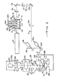
- Figure 2 is a schematic view of the laser, beam attenuator and microscope means in the preferred apparatus of the present invention,
- Figure 3 is a block diagram showing the interface between the detection means and the computer in the preferred apparatus,
- Figure 4 is a schematic diagram showing preferred means for supplying a continuous flow of nutrient medium to cells on a plate adapted to contain the medium,
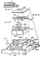
- Figure 5 is an isometric exploded view of the plate shown in Figure 2 showing an x-y moveable stage for the plate,
- Figure 6 is a front cross-sectional view of the plate shown in Figure 5, and ,
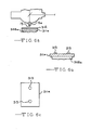
- Figures 6a, 6b and 6c show one slide with a film mounted on it such that wanted cells can be circumscribed by the beam and unwanted cells removed with the film except for discs with the wanted cells.
- Referring to Figures 1 and 2 a focussed radiant energy beam generating means, such as a
laser 10, generates a beam 11. Thelaser 10 is preferably of the argon type and capable of generating light in wavelengths between about 300 and 560 nanometers. The beam 11 is filtered by beam attenuation means 12 provided in the path of the beam 11. Beam deflection means 13, such as mirrors, 13a, 13b, 13c, 13d and 13e shown in Figure 2, are used to provide the beam 11 inside amicroscope 14. A focussedbeam 15 is provided by an objective 15a. The focussedbeam 15 measures about 1 micron in diameter compared to cells of a much greater dimension, for example 40 microns in diameter with nucleus of about 10 microns in diameter. - A
microscope stage 16 supportsplate 17 for supporting the immobilized cells (not shown). Thestage 16 is moveable in an x and y plane perpendicular to the focussedbeam 15 as discussed in connection with Figure 5. Themirrors motors plate 17 in the x and the y plane by the focussedbeam 15. If thestage 16 moves as described hereinafter, then themotors Lens 22 contributes to movement of thebeam 15 in the x or y coordinate without distortion when mirrors 13c and 13d are moved. - Mirror 13e is a dichromatic mirror such that emitted light 23 from the
plate 17 passes through the mirror 13e. Abarrier filter 24 allows only selected luminescence to pass. A mirror or grating element 25 is positioned in the path of the reflected light 23. Ashutter 26 allows instantaneous passage of light to aphoto multiplier tube 27. - The basic elements of the laser microscope apparatus (without the attenuator means 12 or the unique
moveable stage 16 as discussed hereinafter) are described in detail in the Koppel article discussed previously. The laser is available from Lexel, Inc., Sunnyvale, California; the microscope is available from Leitz, Inc., Rock- leigh, New Jersey and themoveable mirrors - The beam attenuation means 12 includes
filters pneumatic actuators Filter 28 is moved to a position out of the beam 11 path by theactuator 32. The remaining filters 29 to 31 are moved in the same manner. Valves V control the movement of theactuators 32 to 35.Pneumatic lines 36 provide air under pressure to valves V. - The microscope includes a conventional binocular viewing means 37,
support 38 and amanual adjustment knob 39. - Referring to Figures 1 and 3, the electronic elements of the present invention are illustrated. The
stage 16 is provided with electricallyactuatable controls 100, as described more fully hereinafter, to provide movement of thestage 16 in the x-y plane perpendicular to the beam 11. Alternatively themotors mirrors stage 16 movement is controlled by acomputer 101 driven by a program stored on a disc(s) 102. Thecomputer 101 can includevideo display 103 and recorder (not shown) connected toterminal 104. Themicroscope 14 functions as afluorescence collection unit 105 from thestage 16. Thephotomultiplier tube 27 functions forfluorescence detection 106 and includes means 106a for counting and/or measuring the fluorescence which is recorded by thecomputer 101. Thus thecomputer 101controls stage 16 movement and records the presence or absence of fluorescence on theplate 17. For slower operation a system without thecomputer 101 could be used; however with much less precision and the speed would be prohibitively slow. Thelens 15a provides beam 11 focussing, themirrors 13a to 13e provide beam direction and thebeam attenuator 12 provides beam attenuation as previously discussed. - In Figure 3, the detector or
photomultiplier tube 27 is coupled to thecomputer 101 by means ofswitch 107 to either: (a) anamplifier discriminator circuit 108 manufactured by Precision Products, Inc., Groton, Connecticut and counter 109 throughinterface 110 to thecomputer 101; or (b) to a rate measuring circuit using the analog amplifier 111 and a 12 bit analog to digital converter 112. The digital output of this unit is fed to thecomputer 101 through theinterface 110. All of this is state of the art. - Figures 4, 5 and 6 show the
plate 17 adapted for cell environmental control onstage 16.Container 200 is fed through line 201 with a mixture of cell growth media from containers 202 and 203 controlled by valves V inlines Container 206 feeds necessary gases tocontainer 200 through valve V inline 207. Pump P supplies the mixed media incontainer 200 and gases vialine 208 to plate 17 as shown more fully in Figures 5 and 6.Line 209 releases spent media to a drain orwaste container 210. Monitoring of media properties is accomplished by transducers sensitive to temperature, carbon dioxide, oxygen and hydrogen ion activity. These transducers are connected tounit 211. - The
stage 16 includes motor 300 for movement in the x direction andmotor 301 for movement in the y direction. The movement is accomplished byscrew shafts 300a and 301 a, attached byplates moveable holder 304 which slides in the x direction onbase 305 and to a second moveable holder 306 which slides in the y direction onfirst holder 304. Such a stage is available from Ealing located in South Natick, Massachusetts. - The second holder 306 is provided with a recess 306a adapted to receive -the
base 307a of asupport 307. Thesupport 307 has spaced apart recesses 307a and 307b and 307c adapted to receive acontainer 308 withinlet conduit 309 andoutlet conduit 310 to be connected tolines container 308 includesintegral pedestals glass slides 311a, 311b and 311c which support the growing cells. Thesupport 307 includesclips 312 for holdingglass cover 313 in position onsupport 307 to completely cover theplate 308 when the cells are not being viewed by the objective 15a. During viewing of the cells on theslides 311 a to 311c c by the objective, thecover 313 is removed; however, the media is still allowed to flow across thecontainer 308. - As shown in Figures 6a to 6c, a variation of the method of the present invention utilizes a
thin film 312 mounted on theslide 311a which supports the cells so that thebeam 15 cuts or fuses thefilm 312 to theslide 311a around the cells for removal of unwanted cells with thefilm 312. Oneslide 311a with thethin film 312 is shown in Figure 6a. Thefilm 312 is generally between about 5 and 200 microns thick and is in contact with theslide 311a a and the cells grow on the opposite side of thefilm 312. The film is preferably composed of a thermoplastic material such as polyvinyl chloride. Thefilm 312 can also be removably bonded to theslide 311a with an adhesive so that thebeam 15 can cut around the wanted cells and the unwanted cells are removed with thefilm 312 from theslide 311 a. Alternatively thebeam 15a can fuse portions of thefilm 312 to theslide 311 a bybeam 15 welding. In either case the unwanted cells andfilm 312 can be stripped from the plate to leave behinddiscs 313 supporting the wanted cells fromfilm 312 fused onto theslide 311a. - The improved method is valuable in sorting for a few wanted cells in a large number of cells, since it produces little cell debris which can affect the wanted cells. Where there are fewer unwanted cells in the cell population, the unwanted cell killing method is preferred.
- Light absorbing materials can be provided on the
slide 311a alone or beneath thefilm 312. This facilitates cell killing or cutting or fusing of thefilm 312 using thebeam 15. - It will be appreciated that the method involving circumscribing wanted cells by cutting or fusing with the
beam 15 can be combined with the method involving killing of the unwanted cells. There is no particular advantage in using the combination for one sorting procedure because of the concern for cell debris which affects wanted cells in the culture medium. - The present invention uses quantitative techniques for the characterization of diffusion in biological membranes which has made it possible to employ laser technology to develop a scanning system capable of selecting a specific sub-population of cells based on a variety of structural and/or physical parameters. The cells do not move because they are supported on
slides 311a to 311c orfilm 312 and can be maintained in a state that is maximally advantageous to the maintenance of cell viability. The central idea of the approach is that cells with the desired property are spared from a pulse of highintensity laser beam 15a capable of destroying them or are circumscribed when they are on thefilm 312. In this manner, a high level of cell enrichment for the defined characteristic is obtained. A significant feature of this system is that cells cultured on slides 311 orfilm 312 may be used for enrichment. This advantage greatly increases the ultimate biological relevance of any information obtained by chemical analysis of the resulting sorted cells. - The intensity of the beam 11 is controlled by one or more
neutral density filters 28 to 31 inserted or removed from the beam 11 path by air-drivensolenoids 32 to 35 that arecomputer 101 controlled preferably in sixteen (16) discrete levels of attenuation. Alternate devices to effect beam attenuation can be acousto-optical and/or electro-optical. A series of diaphragms and mirrors 13a to 13e then guide the beam into the back of themicroscope 14 capable of epi- fluorescence illumination. The microscope objective 15a adjusts the final focus of thelaser beam 15 into the plane of the cells. The dichroic mirror 13e reflects the laser beam 11 down through themicroscope 14 objective while allowing sample luminescence to be transmitted up to thephotomultiplier tube 27 located in a ther- moelectrically cooledhousing 27a. Theelectronic shutter 26 placed in front of thetube 27 acts to protect thetube 27 from high levels of irradiation. The signal from thetube 27 is fed to acomputer 101 for processing and output. - The essential feature of positive cell selection is the maintenance of optimal growth conditions during the sorting cycle. The
microflow container 308 provides a controlled environment for cells which can be further controlled by the computer 101 (not shown): Thiscontainer 308 is preferably metallic and provides a thermal reservoir for temperature control, flow selection and regulating valves for media flow and gas mixing by the system shown in Figure 4. Thiscontainer 308 also provides for time dependent alterations, e.g. discrete growth substance addition, timed light exposure, etc. Sterility of growing cultures is maintained by the flow properties of thecontainer 308. For short working distance the objective 15a is sterilized before use and is positioned in the growth medium. For long working distance objectives, immersion is not necessary. Cells are grown incontainer 308 preferably with about one hundred forty-four mm2 area continuously bathed by the flowing media. - For the purpose of cell sorting, three operational modes can be utilized. Cell sorting on the basis of a fluorescence marker recognition; cell sorting on the basis of a measured physical property; and cell sorting on the basis of a measured dynamic process (time dependent) characteristic.
- The selection occurs as follows. The cells are grown on
slides 311 a to 311 c which can have thefilm 312 on it. The edges of theseslides 311a a to 311c (or film 312) are coated with a strong fluorophore (not shown). A lowintensity scout beam 15 traverses an (x) coordinate of the field. On its return on the same coordinate, thehigh intensity beam 15 is turned on to kill unwanted cells or circumscribe wanted cells on thefilm 312. However, if luminescence were detected during the scout beam traverse, thebeam 15 will be attenuated on its return pass. The positive detection of the differentiating signal by thetube 27 ensures the survival of the selected cells. Detection of the edge fluorophore onslides 311 a to 311c serves as the boundaries for the scan field of thelaser beam 15. The operator need only set theattenuated scout beam 15 on theplate 17. From this point, scanning of the total field is automatic and controlled by thecomputer 101. - The positive cell selection can be based upon measurements of physical properties such as endogenous fluorescence and de-polarization as well as marker recognition. For more sophisticated applications, actual short experiments can be performed after which selection may be based upon membrane parameters such as rotational and/or translational differences and microviscosity. In all cases, these processes result in the isolation of a viable sub-population of cells or functional clones that have undergone selection without mechanical perturbations.
- The instrumentation for these types of measurements can be divided into three (3) groups which are modular in the progression from the simplest to the more complex.
- Type I-This apparatus is designed to provide selection based upon the cell's affinity for an internally or externally directed site specific probe that is fluorescently labeled, e.g.-antibodies, lectins, DNA-RNA intercalating dyes. The basic components for this instrument are a turnable argon or argon-
krypton laser 10, directingoptics 13a to 13e andshutter 21, amicroscope 14, a two-dimensional translatingstage 16 and photon or rate counter 106a. The instrument is controlled by thecomputer 101. - Type II-The addition of incident and excitation polarizers and a monochrometer (not shown) in the emission beam before the
photomultiplier tube 27 extends the capability of a Type I instru- mentto select on the basis of the polarization value of various fluorescently depolarizable dyes, e.g.-DPH, and also provide the researcher with the means to select cells that have altered fluorescence emission profiles for cell incorporated or adsorbed dyes. Selection is now based on actual changes in the physical state ofthe cell ratherthan purely as a function of the presence or absence of a structural component. - Type III-Since alterations in the membrane dynamics of cells have been demonstrated to be intimately involved in cellular activity, the type III instrument is designed to make its selection on the basis of a real time experiment evaluating lateral and/or rotational diffusion. This type of selection could not be performed on the flow separation system of the prior art due to the necessityfortime resolved measurements. Because cells are plated and maintained in a viable environment, long term selections are feasible based on individual cellular experimentation. This type of instrumentation differs from Type II primarily in the
computer 101 software and data processing power. - Operator control is attained by keystroke command. In addition to initiating and terminating a sorting process, the following parameters can be scheduled under program control:
- . a) two-
dimensional stage 16 movement with step magnitude and frequency control. - b) intensity of analytical (scout) and destroy or fuse beams 11.
- c) threshold beam 11 intensity level.
- d) mode selection-marker or dynamic.
- e) threshold for positive response.
- f) single field scan or continuous mode of operation.
- g) method selection-cell destruction or cell isolation.
- h) beam path radius for cell isolation.
- i) control of all
stage 16 operating functions:- i) temperature
- ii) media mixing and flow
- iii) gas injection
- iv) growth control additives
- v) light exposure
- vi) auxiliary time dependent parameters.
- Sorting analysis is now a major research technique in several disciplines, including cancer immunology, hemetology, cell cycle analysis, pathology, biochemistry, general immunology and quantitative cytology. New areas of interest for these methods are continuously emerging in cell biology, pharmacology, and toxicology, microbiology and cytogenetics. Diseases now under investigation with cell sorting technology are leukemia, lymphoma, and other cancers, infectious diseases, auto immune diseases, and genetic disorders. The apparatus of the present invention makes reliable cell selection possible for these investigations.
Claims (18)
Applications Claiming Priority (2)
| Application Number | Priority Date | Filing Date | Title |
|---|---|---|---|
| US403154 | 1982-07-29 | ||
| US06/403,154 US4629687A (en) | 1982-07-29 | 1982-07-29 | Positive selection sorting of cells |
Publications (2)
| Publication Number | Publication Date |
|---|---|
| EP0101572A1 EP0101572A1 (en) | 1984-02-29 |
| EP0101572B1 true EP0101572B1 (en) | 1988-10-19 |
Family
ID=23594656
Family Applications (1)
| Application Number | Title | Priority Date | Filing Date |
|---|---|---|---|
| EP83107289A Expired EP0101572B1 (en) | 1982-07-29 | 1983-07-25 | Positive selection sorting of cells |
Country Status (4)
| Country | Link |
|---|---|
| US (1) | US4629687A (en) |
| EP (1) | EP0101572B1 (en) |
| JP (1) | JPS5942885A (en) |
| DE (1) | DE3378254D1 (en) |
Cited By (1)
| Publication number | Priority date | Publication date | Assignee | Title |
|---|---|---|---|---|
| DE4323129C2 (en) * | 1992-07-24 | 2002-10-02 | Zeiss Carl | Inverted microscope |
Families Citing this family (62)
| Publication number | Priority date | Publication date | Assignee | Title |
|---|---|---|---|---|
| US4824775A (en) * | 1985-01-03 | 1989-04-25 | Molecular Diagnostics, Inc. | Cells labeled with multiple Fluorophores bound to a nucleic acid carrier |
| US5070468A (en) * | 1988-07-20 | 1991-12-03 | Mitsubishi Jukogyo Kabushiki Kaisha | Plant fault diagnosis system |
| US5005927A (en) * | 1989-03-28 | 1991-04-09 | The United States Of America As Represented By The Secretary Of The Air Force | Nonlinear optical microscope |
| EP0501688A1 (en) * | 1991-02-27 | 1992-09-02 | Hitachi, Ltd. | Apparatus and method for applying a laser beam through a microscope |
| JP3067347B2 (en) * | 1991-10-30 | 2000-07-17 | 株式会社島津製作所 | Gel-like bead sorting equipment |
| US5843657A (en) * | 1994-03-01 | 1998-12-01 | The United States Of America As Represented By The Department Of Health And Human Services | Isolation of cellular material under microscopic visualization |
| US5843644A (en) * | 1994-03-01 | 1998-12-01 | The United States Of America As Represented By The Secretary Of The Department Of Health And Human Services | Isolation of cellular material under microscopic visualization using an adhesive/extraction reagent tipped probe |
| US6040139A (en) | 1995-09-19 | 2000-03-21 | Bova; G. Steven | Laser cell purification system |
| DE19603996C2 (en) * | 1996-02-05 | 2002-08-29 | P A L M Gmbh Mikrolaser Techno | Sorting process for planar biological objects with laser beams |
| WO1997029354A1 (en) * | 1996-02-05 | 1997-08-14 | Bayer Aktiengesellschaft | Process and device for sorting and for extraction of biological objects arranged on planar means, such as biological cells or cell organelles, histological sections, chromosome particles etc. using laser beams |
| AU4562497A (en) * | 1996-10-02 | 1998-04-24 | Cell Robotics, Inc. | Microscope with laser port |
| US6087134A (en) * | 1997-01-14 | 2000-07-11 | Applied Imaging Corporation | Method for analyzing DNA from a rare cell in a cell population |
| JP4323571B2 (en) | 1997-01-31 | 2009-09-02 | エックスワイ, インコーポレイテッド | Optical device |
| US6469779B2 (en) | 1997-02-07 | 2002-10-22 | Arcturus Engineering, Inc. | Laser capture microdissection method and apparatus |
| US6495195B2 (en) | 1997-02-14 | 2002-12-17 | Arcturus Engineering, Inc. | Broadband absorbing film for laser capture microdissection |
| US6753161B2 (en) * | 1997-03-27 | 2004-06-22 | Oncosis Llc | Optoinjection methods |
| US6534308B1 (en) * | 1997-03-27 | 2003-03-18 | Oncosis, Llc | Method and apparatus for selectively targeting specific cells within a mixed cell population |
| US5874266A (en) * | 1997-03-27 | 1999-02-23 | Palsson; Bernhard O. | Targeted system for removing tumor cells from cell populations |
| US6514722B2 (en) | 1997-03-27 | 2003-02-04 | Oncosis | Method and apparatus for selectively targeting specific cells within a cell population |
| US6100051A (en) | 1997-06-27 | 2000-08-08 | The United States Of America As Represented By The Department Of Health And Human Services | Method utilizing convex geometry for laser capture microdissection |
| US7075640B2 (en) * | 1997-10-01 | 2006-07-11 | Arcturus Bioscience, Inc. | Consumable for laser capture microdissection |
| US6149867A (en) | 1997-12-31 | 2000-11-21 | Xy, Inc. | Sheath fluids and collection systems for sex-specific cytometer sorting of sperm |
| US6071689A (en) | 1997-12-31 | 2000-06-06 | Xy, Inc. | System for improving yield of sexed embryos in mammals |
| US6720191B1 (en) | 1998-02-03 | 2004-04-13 | The United States Of America As Represented By The Department Of Health And Human Services | Mechanical handling systems for laser capture microdissection |
| US6642018B1 (en) | 1998-03-27 | 2003-11-04 | Oncosis Llc | Method for inducing a response in one or more targeted cells |
| US5972667A (en) * | 1998-05-19 | 1999-10-26 | Cell Robotics, Inc. | Method and apparatus for activating a thermo-enzyme reaction with electromagnetic energy |
| EP1101094B1 (en) * | 1998-07-30 | 2004-09-29 | THE GOVERNMENT OF THE UNITED STATES OF AMERICA, as represented by the Secretary, Department of Health and Human Services | Precision laser capture microdissection utilizing short pulse length |
| US6743601B1 (en) | 1998-12-10 | 2004-06-01 | The United States Of America As Represented By The Department Of Health And Human Services | Non-contact laser capture microdissection |
| JP3582390B2 (en) * | 1999-01-13 | 2004-10-27 | 松下電器産業株式会社 | Automatic search device for fine objects |
| EP1210577A2 (en) | 1999-04-29 | 2002-06-05 | Arcturus Engineering, Inc. | Processing technology for lcm samples |
| US7208265B1 (en) | 1999-11-24 | 2007-04-24 | Xy, Inc. | Method of cryopreserving selected sperm cells |
| DE10003588C2 (en) * | 2000-01-25 | 2002-10-02 | Sl Microtest Wissenschaftliche | Method of isolating part of a layer of biological material |
| EP1269144A1 (en) | 2000-02-16 | 2003-01-02 | Arcturus Engineering, Inc. | Transfer film for laser microcapture |
| EP2258173A3 (en) | 2000-05-09 | 2012-06-13 | Xy, Llc | High purity x-chromosome bearing and y-chromosome bearing populations of spermatozoa |
| US20070196815A1 (en) * | 2000-08-02 | 2007-08-23 | Jason Lappe | Positive Selection Procedure for Optically Directed Selection of Cells |
| WO2002019594A2 (en) * | 2000-08-02 | 2002-03-07 | Arizona Board Of Regents, Acting On Behalf Of Arizona State University | Scanning fluorescence lifetime microscope: directed evolution |
| AU3289202A (en) * | 2000-10-24 | 2002-05-21 | Oncosis Llp | Method and device for selectively targeting cells within a three -dimensional specimen |
| CA2822983C (en) | 2000-11-29 | 2017-05-09 | Xy, Llc | System to separate frozen-thawed spermatozoa into x-chromosome bearing and y-chromosome bearing populations |
| US7713687B2 (en) | 2000-11-29 | 2010-05-11 | Xy, Inc. | System to separate frozen-thawed spermatozoa into x-chromosome bearing and y-chromosome bearing populations |
| US8211629B2 (en) | 2002-08-01 | 2012-07-03 | Xy, Llc | Low pressure sperm cell separation system |
| US8486618B2 (en) | 2002-08-01 | 2013-07-16 | Xy, Llc | Heterogeneous inseminate system |
| CA2534394C (en) | 2002-08-15 | 2013-01-08 | Xy, Inc. | High resolution flow cytometer |
| US7169548B2 (en) | 2002-09-13 | 2007-01-30 | Xy, Inc. | Sperm cell processing and preservation systems |
| US20040077073A1 (en) * | 2002-10-18 | 2004-04-22 | Melvin Schindler | Methods and apparatus for interactive micromanipulation of biological materials |
| DK2959774T3 (en) | 2003-03-28 | 2019-05-13 | Inguran Llc | PROCEDURE FOR CRYCONSERVATION OF SEAT CELLS |
| WO2004104178A2 (en) | 2003-05-15 | 2004-12-02 | Xy, Inc. | Efficient haploid cell sorting for flow cytometer systems |
| US20050095578A1 (en) * | 2003-10-31 | 2005-05-05 | Koller Manfred R. | Method and apparatus for cell permeabilization |
| US7425426B2 (en) * | 2004-03-15 | 2008-09-16 | Cyntellect, Inc. | Methods for purification of cells based on product secretion |
| EP2260854A1 (en) | 2004-03-29 | 2010-12-15 | Inguran, LLC | Sperm suspensions for sorting into x or y chromosome-bearing enriched populations |
| AU2005266930B2 (en) | 2004-07-22 | 2010-09-16 | Inguran, Llc | Process for enriching a population of sperm cells |
| GB0419325D0 (en) * | 2004-09-01 | 2004-09-29 | Perkinelmer Ltd | A method of analysing a sample including fluorescent labels and apparatus therefor |
| WO2006024819A2 (en) * | 2004-09-01 | 2006-03-09 | Perkinelmer Singapore Pte Ltd. | A method of analysing a sample and apparatus therefor |
| US20090208981A1 (en) * | 2005-05-03 | 2009-08-20 | Jia-Ming Chang | Method for Analysis of Interaction Between Small Molecules and Cells and Apparatus thereof |
| GB0603923D0 (en) * | 2006-02-28 | 2006-04-05 | Perkinelmer Ltd | Apparatus and methods for imaging and modification of biological samples |
| UA102854C2 (en) | 2008-06-30 | 2013-08-27 | Микробикс Байосистемз Инк. | Method and device for sorting of cells |
| WO2010081171A2 (en) | 2009-01-12 | 2010-07-15 | Cyntellect, Inc. | Laser mediated sectioning and transfer of cell colonies |
| US8665439B2 (en) * | 2009-06-30 | 2014-03-04 | Microbix Biosystems, Inc. | Method and apparatus for limiting effects of refraction in cytometry |
| EP2554657B1 (en) * | 2010-04-02 | 2019-02-20 | National Institute of Advanced Industrial Science And Technology | Method for separating cells, cell culture medium, and device for separating cells |
| MX338778B (en) | 2011-02-15 | 2016-05-02 | Microbix Biosystems Inc | Methods, systems, and apparatus for performing flow cytometry. |
| US9725711B2 (en) | 2014-03-10 | 2017-08-08 | Celleraser, Llc | Method and device for selective hyperthermic damage of target cells |
| US10876086B2 (en) * | 2015-06-01 | 2020-12-29 | Kataoka Corporation | Cell treatment method, laser processing machine, and cell culture vessel |
| JP6033980B1 (en) * | 2016-06-01 | 2016-11-30 | 株式会社片岡製作所 | Cell processing system |
Family Cites Families (19)
| Publication number | Priority date | Publication date | Assignee | Title |
|---|---|---|---|---|
| US3941670A (en) * | 1970-11-12 | 1976-03-02 | Massachusetts Institute Of Technology | Method of altering biological and chemical activity of molecular species |
| US3712746A (en) * | 1971-07-29 | 1973-01-23 | Gen Electric | Device for optically determining microbial colony population on growth surface |
| DE2141387C3 (en) * | 1971-08-18 | 1975-12-11 | Ernst Dr. 8000 Muenchen Remy | Process for the evaporation, destruction, excitation and / or ionization of sample material limited to micro-areas as well as arrangement for carrying out the process |
| US3984307A (en) * | 1973-03-05 | 1976-10-05 | Bio/Physics Systems, Inc. | Combined particle sorter and segregation indicator |
| US4045772A (en) * | 1974-04-29 | 1977-08-30 | Geometric Data Corporation | Automatic focusing system |
| JPS5212982A (en) * | 1975-07-22 | 1977-01-31 | Olympus Optical Co Ltd | Apparatus for automatic incubation |
| US4087685A (en) * | 1977-01-11 | 1978-05-02 | International Business Machines Corporation | Fluorescent microanalytical system and method for detecting and identifying organic materials |
| US4090128A (en) * | 1977-02-15 | 1978-05-16 | Coulter Electronics, Inc. | Aperture module for use in particle testing apparatus |
| DE2716095C2 (en) * | 1977-04-12 | 1987-02-19 | Becton, Dickinson and Co., Paramus, N.J. | Method for controlling the trajectory of particles suspended in an electrolyte and device for carrying out this method |
| JPS53135660A (en) * | 1977-04-30 | 1978-11-27 | Olympus Optical Co Ltd | Fluorescent photometric microscope using laser light |
| DE2739828C2 (en) * | 1977-09-03 | 1986-07-03 | Gesellschaft für Strahlen- und Umweltforschung mbH, 8000 München | Device for analyzing samples |
| US4213703A (en) * | 1978-05-30 | 1980-07-22 | Beckman Instruments, Inc. | Photometer with stationary sample holder and rotatable shutter |
| US4209256A (en) * | 1978-07-21 | 1980-06-24 | Smithkline Corporation | Liquid flow viewing cell and method for analyzing liquid stream |
| US4172227A (en) * | 1978-07-21 | 1979-10-23 | Becton, Dickinson And Company | Flow microfluorometer |
| US4354114A (en) * | 1979-10-09 | 1982-10-12 | Karnaukhov Valery N | Apparatus for investigation of fluorescence characteristics of microscopic objects |
| US4326934A (en) * | 1979-12-31 | 1982-04-27 | Pohl Herbert A | Continuous dielectrophoretic cell classification method |
| US4395493A (en) * | 1981-05-14 | 1983-07-26 | Coulter Electronics, Inc. | Monolayer device using filter techniques |
| US4395397A (en) * | 1981-09-17 | 1983-07-26 | Sidney Farber Cancer Institute, Inc. | Apparatus and method for killing unwanted cells |
| US4513438A (en) * | 1982-04-15 | 1985-04-23 | Coulter Electronics, Inc. | Automated microscopy system and method for locating and re-locating objects in an image |
-
1982
- 1982-07-29 US US06/403,154 patent/US4629687A/en not_active Expired - Lifetime
-
1983
- 1983-07-25 EP EP83107289A patent/EP0101572B1/en not_active Expired
- 1983-07-25 DE DE8383107289T patent/DE3378254D1/en not_active Expired
- 1983-07-29 JP JP58140443A patent/JPS5942885A/en active Granted
Non-Patent Citations (1)
| Title |
|---|
| JOURNAL OF NEUROSCIENCE METHODS, vol. 3, 1980 H.L. HIGGINS et al. "Selective cell destruction and precise neurite transection in neuroblastoma cultures with pulsed ultraviolet laser microbeam irradiation : An analysis of mechanisms and transection reliability with light and scanning electron microscopy", pp. 83-95, 98, 99 * |
Cited By (1)
| Publication number | Priority date | Publication date | Assignee | Title |
|---|---|---|---|---|
| DE4323129C2 (en) * | 1992-07-24 | 2002-10-02 | Zeiss Carl | Inverted microscope |
Also Published As
| Publication number | Publication date |
|---|---|
| EP0101572A1 (en) | 1984-02-29 |
| JPS5942885A (en) | 1984-03-09 |
| US4629687A (en) | 1986-12-16 |
| DE3378254D1 (en) | 1988-11-24 |
| JPH0254907B2 (en) | 1990-11-22 |
Similar Documents
| Publication | Publication Date | Title |
|---|---|---|
| US4624915A (en) | Positive selection sorting of cells | |
| US4629687A (en) | Positive selection sorting of cells | |
| US11686665B2 (en) | Microfluidic system with combined electrical and optical detection for high accuracy particle sorting and methods thereof | |
| US9279749B2 (en) | Laser microdissection method and apparatus | |
| EP2258171B1 (en) | Flow cytometer for differentiating X-chromosome bearing and Y-chromosome bearing populations of spermatozoa | |
| US5879625A (en) | Optical selection and collection of DNA fragments | |
| US4756427A (en) | Method and apparatus for sorting particles | |
| CA2433296C (en) | Focused acoustic ejection cell sorting system and method | |
| US4500641A (en) | Flow cytometer for identifying algae by chlorophyll fluorescence | |
| US20040106206A1 (en) | Laser capture microdissection vacuum hold-down | |
| US20030124516A1 (en) | Method of using optical interrogation to determine a biological property of a cell or population of cells | |
| US20040077073A1 (en) | Methods and apparatus for interactive micromanipulation of biological materials | |
| US20020108859A1 (en) | Methods for modifying interaction between dielectric particles and surfaces | |
| WO2002057775A1 (en) | Electrical conductive containment system | |
| AU785026B2 (en) | Facs assisted methods for introducing individual chromosomes into cells | |
| US7456938B2 (en) | Laser microdissection on inverted polymer films | |
| US20200096448A1 (en) | Method and device for providing a cell line having a desired target protein expression | |
| Tanke et al. | Selection of defined cell types by flow-cytometric cell sorting | |
| Métézeau | Image and flow cytometry: companion techniques for adherent and non-adherent cell analysis and sorting | |
| CN122016611A (en) | Automated flow cytometry preparation and collection system and method of use thereof |
Legal Events
| Date | Code | Title | Description |
|---|---|---|---|
| PUAI | Public reference made under article 153(3) epc to a published international application that has entered the european phase |
Free format text: ORIGINAL CODE: 0009012 |
|
| 17P | Request for examination filed |
Effective date: 19830725 |
|
| AK | Designated contracting states |
Designated state(s): DE FR GB |
|
| EL | Fr: translation of claims filed | ||
| EM | Fr: revised translation of claims filed | ||
| 17Q | First examination report despatched |
Effective date: 19860207 |
|
| GRAA | (expected) grant |
Free format text: ORIGINAL CODE: 0009210 |
|
| AK | Designated contracting states |
Kind code of ref document: B1 Designated state(s): DE FR GB |
|
| REF | Corresponds to: |
Ref document number: 3378254 Country of ref document: DE Date of ref document: 19881124 |
|
| ET | Fr: translation filed | ||
| PLBE | No opposition filed within time limit |
Free format text: ORIGINAL CODE: 0009261 |
|
| STAA | Information on the status of an ep patent application or granted ep patent |
Free format text: STATUS: NO OPPOSITION FILED WITHIN TIME LIMIT |
|
| 26N | No opposition filed | ||
| REG | Reference to a national code |
Ref country code: GB Ref legal event code: IF02 |
|
| PGFP | Annual fee paid to national office [announced via postgrant information from national office to epo] |
Ref country code: FR Payment date: 20020702 Year of fee payment: 20 |
|
| PGFP | Annual fee paid to national office [announced via postgrant information from national office to epo] |
Ref country code: GB Payment date: 20020717 Year of fee payment: 20 |
|
| PGFP | Annual fee paid to national office [announced via postgrant information from national office to epo] |
Ref country code: DE Payment date: 20020730 Year of fee payment: 20 |
|
| PG25 | Lapsed in a contracting state [announced via postgrant information from national office to epo] |
Ref country code: GB Free format text: LAPSE BECAUSE OF EXPIRATION OF PROTECTION Effective date: 20030724 |
|
| REG | Reference to a national code |
Ref country code: GB Ref legal event code: PE20 |