EP0101568A2 - Structure for attaching carpeting to vehicle body - Google Patents
Structure for attaching carpeting to vehicle body Download PDFInfo
- Publication number
- EP0101568A2 EP0101568A2 EP83107226A EP83107226A EP0101568A2 EP 0101568 A2 EP0101568 A2 EP 0101568A2 EP 83107226 A EP83107226 A EP 83107226A EP 83107226 A EP83107226 A EP 83107226A EP 0101568 A2 EP0101568 A2 EP 0101568A2
- Authority
- EP
- European Patent Office
- Prior art keywords
- support member
- floor
- pillar garnish
- carpeting
- carpet
- Prior art date
- Legal status (The legal status is an assumption and is not a legal conclusion. Google has not performed a legal analysis and makes no representation as to the accuracy of the status listed.)
- Withdrawn
Links
Images


Classifications
-
- B—PERFORMING OPERATIONS; TRANSPORTING
- B60—VEHICLES IN GENERAL
- B60N—SEATS SPECIALLY ADAPTED FOR VEHICLES; VEHICLE PASSENGER ACCOMMODATION NOT OTHERWISE PROVIDED FOR
- B60N3/00—Arrangements or adaptations of other passenger fittings, not otherwise provided for
- B60N3/04—Arrangements or adaptations of other passenger fittings, not otherwise provided for of floor mats or carpets
- B60N3/046—Arrangements or adaptations of other passenger fittings, not otherwise provided for of floor mats or carpets characterised by the fixing means
-
- Y—GENERAL TAGGING OF NEW TECHNOLOGICAL DEVELOPMENTS; GENERAL TAGGING OF CROSS-SECTIONAL TECHNOLOGIES SPANNING OVER SEVERAL SECTIONS OF THE IPC; TECHNICAL SUBJECTS COVERED BY FORMER USPC CROSS-REFERENCE ART COLLECTIONS [XRACs] AND DIGESTS
- Y10—TECHNICAL SUBJECTS COVERED BY FORMER USPC
- Y10T—TECHNICAL SUBJECTS COVERED BY FORMER US CLASSIFICATION
- Y10T403/00—Joints and connections
- Y10T403/16—Joints and connections with adjunctive protector, broken parts retainer, repair, assembly or disassembly feature
- Y10T403/1608—Holding means or protector functioning only during transportation, assembly or disassembly
Definitions
- a carpet support member is located so as to bridge the space between a floor panel and the upper edge ' of the side sill outer panel.
- An enclosed space is, therefore, defined below the carpet support member in conjunction with the floor panel and side sill inner panel.
- An electrical wire harness runs through this space.
- a cut- out of substantially trapezoidal shape is provided along one edge of the carpet support member and onto the sloping surface thereof opposite the lower end of a center pillar garnish described hereinafter.
- a layer of floor carpeting rests on the carpet support member.
- the center pillar garnish is mounted so as to cover the center pillar inner member.
- the lower end of the center pillar garnish is substantially trapezoidal.
- the inner surface of the lower end of the center pillar garnish is brought into close contact with the floor carpeting over the cutout of the carpet support member.
- the edge of the floor carpeting other than the portion enclosed by the lower end of the center pillar garnish is enclosed by a kicking plate. It should also be noted that the distance between the lower end of the center pillar garnish and the carpet support member is previously designed to be narrower than the thickness of ordinary floor carpeting. Care is taken to prevent a gap from occurring between the floor carpeting and the lower end of the center pillar garnish. Therefore, the portion of the floor carpeting which is positioned over the cutout of the carpet support member is depressed into the cutout due to the force applied by the trapezoidal lower end of the center pillar garnish when the center pillar garnish is mounted on the center pillar inner member.
- the contact area between the lower end of the center pillar garnish and the floor carpeting is accordingly reduced, the reactive force of the floor carpeting against the center pillar garnish is reduced, so that the center pillar garnish can be easily installed in its intended position on the center pillar inner member and the floor carpet rests properly on the carpet support member while remaining clamped in place by the lower end of the center pillar garnish. Consequently, the floor carpet can fixedly be attached to the floor panel and carpet support member.
- Fig. 1 shows a conventional structure of a ' vehicle body for attaching floor carpeting, in particular the periphery of a center pillar.
- a pillar garnish such as a center pillar garnish and the floor carpeting itself are omitted from Fig. 1.
- Fig. 2 shows the conventional structure of the vehicle body for attaching the floor carpeting.
- the center pillar garnish and the floor carpeting are both installed in place over a corresponding panel of the vehicle body.
- numeral 1 denotes a floor panel of the vehicle body and numeral 2 denotes a side sill inner panel elongated along the vehicle body.
- the floor panel 1 is bent downwards along one longitudinal edge and is fixed to the lower edge of the side sill inner panel 2.
- Numeral 3 denotes a side sill outer panel, to opposite sides of the inside, upper edge of which the upper edge of the side sill inner panel 2 and the lower end of a center pillar inner member 4 are fixed and to the outside, upper edge of which the lower end of a center pillar outer member 5 is fixed.
- Numeral 6 denotes a carpet support member, the upper edge of which is fixed to the upper edge of the side sill inner panel 2 by means of screws 7 and lower end of which is fixed to the floor panel 1 by means of screws 7. Therefore, as best seen in Fig. 3 a space S of substantially a triangular shape in cross-section is formed .by these three members, i.e., side sill inner panel 2, floor panel 1, and floor carpet support member 6. An electrical wiring harness (not shown) runs through the space S.
- numeral 6' denotes a stopper member attached to the upper edge of the carpet support member 6 for securing the carpet support member 6 to the side sill inner panel 2.
- a cutout 8 of substantially trapezoidal shape is provided along the outside edge of the carpet support member 6, i.e., the edge adjacent to the lower end of the center pillar inner member 4.
- the bottom edge of the cutout 8 extends onto the sloping portion of the carpet support member 6, which face the lower end 10a of a center pillar garnish 10 to be described hereinafter.
- a floor carpet 9 rests on the floor panel 1 and on the carpet support member 6.
- An inner surface of the trapezoidal lower end 10a of the center pillar garnish 10 clamps part of the outside edge of the floor carpet 9 which rests on the cutout 8 provided in the carpet support member 6.
- the rest of the outside edge of the floor carpet 9 is later tightly clamped to the side sill inner panel 2 by means of a kicking plate (not shown).
- the clearance between the lower end 10a of the center pillar garnish 10 and the carpet support member 6 is previously selected to be narrower than the thickness of the floor carpet 9 so that the clearance is completely filled by the floor carpet 9 when the center pillar -garnish 10 is mounted on the center pillar inner member 4 . Therefore, the portion of the outside edge 9a of the floor carpet 9 which rests on the cutout 8 of the carpet support member 6 is pushed into the cutout 8.
- the area of contact between the carpet 9 and the lower end 10a of the center pillar garnish 10 is thus reduced so that the reactive force of the floor carpet 9 against the center pillar garnish 10 is accordingly reduced.
- the center pillar garnish 10 is fixed in place and the outside edge 9a of the floor carpet 9 is held in close contact with the upper surface of the carpet support member 6.
- numeral 16 denotes the carpet support member which in accordance with the present invention has sawteeth 19 provided along the edges of the conventional trapezoidal cutout 18.
- the base of each of the sawteeth 19 starts on the sloping surface of the carpet support member 16 at a point opposite to the lower edge of the lower end 10a of the center pillar garnish 10.
- the lower end 10a of the center pillar garnish 10 acts to clamp the outside edge 9a of the floor carpet 9 which rests on the sawteeth 19 provided around the cutout 18.
- a stooper member 16' is attached to the carpet support member 16.
- the carpet support member 16 is fixed to a point near the juncture of the side sill inner panel 2 and side sill outer panel 3 by means of the screws 7.
- the floor carpet 9 is layed over the carpet support member 16.
- the lower end 10a of the center pillar garnish 10 pushes against the portion of the floor carpet 9 which rests on the sawteeth 19 of the cutout 18 provided in the carpet support member 16.
- the sawteeth 19 tend to bend downward into the space S so that the reactive force between the lower end 10a of the center pillar garnish 10 and the carpet 9 is reduced.
- the center pillar garnish 10 can, thus, easily be fixed in place.
- Fig. 8 shows a second preferred embodiment according to the present invention.
- the cutout 18 edged with sawteeth 19 is located at one end of the outside edge of the carpet support member 16 opposite the lower end of a front pillar inner member 20.
- the outside edge 9a of the floor carpet 9 rests on the sawteeth 19 provided along the cutout 18.
- the lower end 21a of the front pillar garnish 21 clamps the portion of the floor carpet 9 facing the sawteeth 19 of the cutout 18.
- center pillar garnish 10 and front pillar garnish 21 as means for clamping the the floor carpet 9
- rear pillar garnish may obviously also be used for this purpose.
- sawteeth are provided around the edges of a cutout at the edge of a carpet support member extending between a side sill inner panel and a floor panel and the lower end of a pillar garnish is installed so as to compress a portion of the floor carpet against the sawteeth of the cutout. Therefore, relatively thin floor carpeting can be securely clamped in the clearance between the lower end of the pillar garnish and the carpet support member. In addition, thicker floor carpeting can also fit into the clearance since the sawteeth will bend to accommodate the floor carpet in response to the compression force of the pillar garnish and so the reactive force of the floor carpet against the lower end of a pillar garnish will also be reduced. Consequently, the pillar garnish can also easily be fitted into place.
Landscapes
- Engineering & Computer Science (AREA)
- Transportation (AREA)
- Mechanical Engineering (AREA)
- Body Structure For Vehicles (AREA)
- Vehicle Interior And Exterior Ornaments, Soundproofing, And Insulation (AREA)
- Passenger Equipment (AREA)
Abstract
Description
- The present invention relates generally to a structure for attaching floor carpeting to a vehicle body interior, and specifically to the structural elements of the vehicle body to which the floor carpeting is appropriately attached, wherein floor carpeting of any thickness can fit into a gap provided structurally between the lower end of a garnish such as a center pillar garnish and the upper surface of a carpet support member which is supported by a side sill panel and a floor panel:,
- A conventional structure for attaching carpeting to a vehicle body is described below.
- A structure for attaching carpeting to a vehicle body thereto comprises: (a) a floor panel; (b) a side sill inner panel; (c) a side sill outer panel attached to the side sill inner panel; (d) a center pillar outer member, the lower end of which is attached to the top edge of the side sill outer panel; and (e) a center pillar inner member, the lower end of which is attached to the top edge of the side sill outer panel to which the upper edge of the side sill inner panel is fixed.
- A carpet support member is located so as to bridge the space between a floor panel and the upper edge 'of the side sill outer panel. An enclosed space is, therefore, defined below the carpet support member in conjunction with the floor panel and side sill inner panel. An electrical wire harness runs through this space. A cut- out of substantially trapezoidal shape is provided along one edge of the carpet support member and onto the sloping surface thereof opposite the lower end of a center pillar garnish described hereinafter. A layer of floor carpeting rests on the carpet support member. The center pillar garnish is mounted so as to cover the center pillar inner member. The lower end of the center pillar garnish is substantially trapezoidal. The inner surface of the lower end of the center pillar garnish is brought into close contact with the floor carpeting over the cutout of the carpet support member. It should be noted that the edge of the floor carpeting other than the portion enclosed by the lower end of the center pillar garnish is enclosed by a kicking plate. It should also be noted that the distance between the lower end of the center pillar garnish and the carpet support member is previously designed to be narrower than the thickness of ordinary floor carpeting. Care is taken to prevent a gap from occurring between the floor carpeting and the lower end of the center pillar garnish. Therefore, the portion of the floor carpeting which is positioned over the cutout of the carpet support member is depressed into the cutout due to the force applied by the trapezoidal lower end of the center pillar garnish when the center pillar garnish is mounted on the center pillar inner member. Since the contact area between the lower end of the center pillar garnish and the floor carpeting is accordingly reduced, the reactive force of the floor carpeting against the center pillar garnish is reduced, so that the center pillar garnish can be easily installed in its intended position on the center pillar inner member and the floor carpet rests properly on the carpet support member while remaining clamped in place by the lower end of the center pillar garnish. Consequently, the floor carpet can fixedly be attached to the floor panel and carpet support member.
- However, there is a problem in such a.structure for attaching carpeting to a vehicle body in the case of floor carpet thicker than normal for use in a luxury automotive vehicle. Since the cut-out provided in the carpet support member of the structure described above extends only partly as far down as does the lower the center pillar garnish, the lower end of the center pillar garnish is pushed upward during its assembly onto the vehicle body due to the increased thickness of the floor carpet. Consequently, the center pillar garnish cannot be mounted in its normal position on the center pillar inner member.
- In addition, there exists another problem in the case of floor carpeting thinner than normal for use in an economy automotive vehicle. In this case, a gap will exist .between the trapezoidal lower end of the center pillar garnish and the floor carpeting so that the appearance around such a pillar garnish is adversely affected, efficiency of assembly of such a pillar garnish is reduced, and, in the worst case, the floor carpet may gradually separate from the carpet support member due to repetitive applications of external forces on the floor carpeting.
- With the above-described problems in mind, it is an object of the present invention to provide an improved structure for attaching carpeting substantially permanently to the vehicle body, wherein a sawtooth edged cutout is provided at a portion of a carpet support member opposite a pillar member, the lower edge of the sawtooth-edged cutout being directly opposite the lowest edge of a trapezoidal lower end of a pillar garnish and the pillar garnish is mounted on the pillar member such that the trapezoidal lower end thereof compresses the portion of the floor carpet positioned over the sawtooth-edged cutout.
- A more complete understanding of the present invention may be obtained from the following detailed description taken in conjunction with the drawings in which like reference numerals designate corresponding elements and in which:
- Fig. 1 is a perspective view of a section of a conventional structure for attaching floor carpeting to a .vehicle body before the floor carpet and center pillar garnish are installed on the vehicle body;
- Fig. 2 is a perspective view of the conventional structure shown in Fig. 1 with the floor carpeting installed;
- Fig. 3 is a cros-sectional view taken along the curve III-III of Fig. 2;
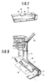
- Fig. 4 is a perspective view of a section of a structure for attaching floor carpeting to the vehicle body according to a first preferred embodiment of the present invention before the floor carpet and center pillar garnish are installed on the vehicle body;
- Fig. 5 is a view similar to Fig. 2 of .the first embodiment of the present invention;
- Fig. 6 is a cross sectional view taken along the curve VI-VI of Fig. 5;
- Fig. 7 is a perspective view of a carpet support member shown in Figs. 4 through 6 having a sawtooth-edged cutout according to the present invention; and
- Fig. 8 is a perspective view of a section of a structure for attaching floor carpeting to the vehicle body according to a second preferred embodiment of the present invention.
- Reference will be made to the drawings in order to facilitate understanding of the present invention.
- Fig. 1 shows a conventional structure of a 'vehicle body for attaching floor carpeting, in particular the periphery of a center pillar. A pillar garnish such as a center pillar garnish and the floor carpeting itself are omitted from Fig. 1.
- Fig. 2 shows the conventional structure of the vehicle body for attaching the floor carpeting. In this view, the center pillar garnish and the floor carpeting are both installed in place over a corresponding panel of the vehicle body.
- Fig. 3 shows a cross section of the structure shown in Fig. 2 taken along the curve III-III.
- In these drawings,
numeral 1 denotes a floor panel of the vehicle body andnumeral 2 denotes a side sill inner panel elongated along the vehicle body. Thefloor panel 1 is bent downwards along one longitudinal edge and is fixed to the lower edge of the side sillinner panel 2. Numeral 3 denotes a side sill outer panel, to opposite sides of the inside, upper edge of which the upper edge of the side sillinner panel 2 and the lower end of a center pillarinner member 4 are fixed and to the outside, upper edge of which the lower end of a center pillarouter member 5 is fixed. Numeral 6 denotes a carpet support member, the upper edge of which is fixed to the upper edge of the side sillinner panel 2 by means ofscrews 7 and lower end of which is fixed to thefloor panel 1 by means ofscrews 7. Therefore, as best seen in Fig. 3 a space S of substantially a triangular shape in cross-section is formed .by these three members, i.e., side sillinner panel 2,floor panel 1, and floorcarpet support member 6. An electrical wiring harness (not shown) runs through the space S. In Fig. 3, numeral 6' denotes a stopper member attached to the upper edge of thecarpet support member 6 for securing thecarpet support member 6 to the side sillinner panel 2. - As best seen in Fig. 1, a
cutout 8 of substantially trapezoidal shape is provided along the outside edge of thecarpet support member 6, i.e., the edge adjacent to the lower end of the center pillarinner member 4. The bottom edge of thecutout 8 extends onto the sloping portion of thecarpet support member 6, which face thelower end 10a of acenter pillar garnish 10 to be described hereinafter. Afloor carpet 9 rests on thefloor panel 1 and on thecarpet support member 6. An inner surface of the trapezoidallower end 10a of the center pillar garnish 10 clamps part of the outside edge of thefloor carpet 9 which rests on thecutout 8 provided in thecarpet support member 6. The rest of the outside edge of thefloor carpet 9 is later tightly clamped to the side sillinner panel 2 by means of a kicking plate (not shown). The clearance between thelower end 10a of thecenter pillar garnish 10 and thecarpet support member 6 is previously selected to be narrower than the thickness of thefloor carpet 9 so that the clearance is completely filled by thefloor carpet 9 when the center pillar -garnish 10 is mounted on the center pillar inner member 4. Therefore, the portion of theoutside edge 9a of thefloor carpet 9 which rests on thecutout 8 of thecarpet support member 6 is pushed into thecutout 8. The area of contact between thecarpet 9 and thelower end 10a of thecenter pillar garnish 10 is thus reduced so that the reactive force of thefloor carpet 9 against thecenter pillar garnish 10 is accordingly reduced. Thecenter pillar garnish 10 is fixed in place and theoutside edge 9a of thefloor carpet 9 is held in close contact with the upper surface of thecarpet support member 6. - Figs. 4 through 7 show a first preferred embodiment according to the present invention.
- In these drawings,
numeral 16 denotes the carpet support member which in accordance with the present invention hassawteeth 19 provided along the edges of the conventionaltrapezoidal cutout 18. The base of each of thesawteeth 19 starts on the sloping surface of thecarpet support member 16 at a point opposite to the lower edge of thelower end 10a of thecenter pillar garnish 10. Thelower end 10a of thecenter pillar garnish 10 acts to clamp theoutside edge 9a of thefloor carpet 9 which rests on thesawteeth 19 provided around thecutout 18. As shown in Fig. 6, a stooper member 16' is attached to thecarpet support member 16. - As in the conventional structure, the
carpet support member 16 is fixed to a point near the juncture of the side sillinner panel 2 and side sillouter panel 3 by means of thescrews 7. Thefloor carpet 9 is layed over thecarpet support member 16. Thelower end 10a of the center pillar garnish 10 pushes against the portion of thefloor carpet 9 which rests on thesawteeth 19 of thecutout 18 provided in thecarpet support member 16. In response, thesawteeth 19 tend to bend downward into the space S so that the reactive force between thelower end 10a of thecenter pillar garnish 10 and thecarpet 9 is reduced. Thecenter pillar garnish 10 can, thus, easily be fixed in place. In this way, since the reactive force of thefloor carpet 9 against thecenter pillar garnish 10 is reduced, floor carpeting of nearly any thickness can fit. into the clearance between thelower end 10a of thecenter pillar garnish 10 andcarpet support member 16, provided the clearance is set to be slightly smaller than the thickness ofregular floor carpeting 9. This also ensures that there will be no clearance between thelower end 10a of thecenter pillar garnish 10 and the corresponding edge of thefloor carpet 9 after thecenter pillar garnish 10 is installed. - Fig. 8 shows a second preferred embodiment according to the present invention.
- In this embodiment, the
cutout 18 edged withsawteeth 19 is located at one end of the outside edge of thecarpet support member 16 opposite the lower end of a front pillarinner member 20. Theoutside edge 9a of thefloor carpet 9 rests on thesawteeth 19 provided along thecutout 18. The lower end 21a of thefront pillar garnish 21 clamps the portion of thefloor carpet 9 facing thesawteeth 19 of thecutout 18. - Although the preferred embodiments describe only the
center pillar garnish 10 andfront pillar garnish 21 as means for clamping the thefloor carpet 9, a rear pillar garnish may obviously also be used for this purpose. - In summary, sawteeth are provided around the edges of a cutout at the edge of a carpet support member extending between a side sill inner panel and a floor panel and the lower end of a pillar garnish is installed so as to compress a portion of the floor carpet against the sawteeth of the cutout. Therefore, relatively thin floor carpeting can be securely clamped in the clearance between the lower end of the pillar garnish and the carpet support member. In addition, thicker floor carpeting can also fit into the clearance since the sawteeth will bend to accommodate the floor carpet in response to the compression force of the pillar garnish and so the reactive force of the floor carpet against the lower end of a pillar garnish will also be reduced. Consequently, the pillar garnish can also easily be fitted into place.
- It will be fully understood by those skilled in the art that various modifications may be made in the preferred embodiments described hereinbefore without departing the spirit and scope of the present invention, which is defined by the appended claims.
Claims (8)
characterized in that said cutout (18) is edged with a plurality of resilient structural features (19) which flex into the space (S) of substantially triangular cross-section under the pressing force of said pillar garnish (10;21).
characterized in that said plurality of resilient structural features edging said cutout (18) of the carpet support member (16) are sawteeth (19).
characterized in that the lower edge of said cutout (18) and the lower edge of said pillar garnish (10;21) are at the same elevation above the floor panel (1).
characterized in that said pillar garnish is a center pillar garnish (10).
characterized in that said pillar garnish is a front pillar garnish (21).
characterized in that said pillar garnish is a rear pillar garnish.
characterized in that the distance between the lower end of said pillar garnish (10;21) and said carpet support member (16) is previously set to be less than the predetermined thickness of the floor carpeting (9) before being compressed.
Applications Claiming Priority (2)
| Application Number | Priority Date | Filing Date | Title |
|---|---|---|---|
| JP57146184A JPS5938140A (en) | 1982-08-25 | 1982-08-25 | Setting structure of floor carpet for vehicle |
| JP146184/82 | 1982-08-25 |
Publications (2)
| Publication Number | Publication Date |
|---|---|
| EP0101568A2 true EP0101568A2 (en) | 1984-02-29 |
| EP0101568A3 EP0101568A3 (en) | 1987-08-19 |
Family
ID=15402032
Family Applications (1)
| Application Number | Title | Priority Date | Filing Date |
|---|---|---|---|
| EP83107226A Withdrawn EP0101568A3 (en) | 1982-08-25 | 1983-07-22 | Structure for attaching carpeting to vehicle body |
Country Status (3)
| Country | Link |
|---|---|
| US (1) | US4532671A (en) |
| EP (1) | EP0101568A3 (en) |
| JP (1) | JPS5938140A (en) |
Families Citing this family (3)
| Publication number | Priority date | Publication date | Assignee | Title |
|---|---|---|---|---|
| JPS61158572U (en) * | 1985-03-25 | 1986-10-01 | ||
| US5288121A (en) * | 1993-02-25 | 1994-02-22 | Grant Industries, Inc. | Automobile trim strip and carpet retaining clip |
| KR102664126B1 (en) * | 2019-12-16 | 2024-05-09 | 현대자동차주식회사 | Side sill structure for vehicle |
Family Cites Families (3)
| Publication number | Priority date | Publication date | Assignee | Title |
|---|---|---|---|---|
| US1206759A (en) * | 1916-05-22 | 1916-11-28 | Andreas Hanauer | Carpet anchor-clip. |
| DE7036510U (en) * | 1970-10-02 | 1971-02-04 | Opel Adam Ag | DEVICE FOR FASTENING THE FLOOR COVERING OF VEHICLES, IN PARTICULAR MOTOR VEHICLES. |
| US4069542A (en) * | 1976-12-01 | 1978-01-24 | Carder William E | Carpet securing strips |
-
1982
- 1982-08-25 JP JP57146184A patent/JPS5938140A/en active Pending
-
1983
- 1983-07-11 US US06/512,563 patent/US4532671A/en not_active Expired - Fee Related
- 1983-07-22 EP EP83107226A patent/EP0101568A3/en not_active Withdrawn
Also Published As
| Publication number | Publication date |
|---|---|
| EP0101568A3 (en) | 1987-08-19 |
| JPS5938140A (en) | 1984-03-01 |
| US4532671A (en) | 1985-08-06 |
Similar Documents
| Publication | Publication Date | Title |
|---|---|---|
| US7040063B2 (en) | Use of a window glass comprising a profiled bead for installing it in an opening | |
| JPS63130446A (en) | Bumper for automobile | |
| EP0136487B1 (en) | Mounting construction of window sealed glass | |
| US4629204A (en) | Method for fixing a mud flap to a motor vehicle, a mud flap and a device for performing the method | |
| KR102193300B1 (en) | Pillar plate for vehicle | |
| US4718714A (en) | Vehicle support structure for a detachable roof | |
| EP0101568A2 (en) | Structure for attaching carpeting to vehicle body | |
| US3837130A (en) | Window mounting arrangement | |
| JPH11348657A (en) | Room lamp mounting structure | |
| US5421130A (en) | Holding element for a glass pane in the frame of a motor vehicle | |
| KR910008194B1 (en) | Peripheral garnish mold of window glass for vehicles | |
| JPS6226170A (en) | Hood for automobile | |
| US6070930A (en) | Structure for positioning window shield panel for vehicle and method of mounting window shield panel | |
| JPH0515217Y2 (en) | ||
| JP3447109B2 (en) | Rising part from flat roof | |
| JPS6226531Y2 (en) | ||
| JPS6121293Y2 (en) | ||
| JPH0119542Y2 (en) | ||
| JPH066971Y2 (en) | Adhesive window panel dam rubber for vehicles | |
| JPH052334Y2 (en) | ||
| JPS6216110Y2 (en) | ||
| US20010041090A1 (en) | Method for mounting an inside cover section of a motor vehicle | |
| JPH0335126B2 (en) | ||
| JPH046354Y2 (en) | ||
| JPH0347936Y2 (en) |
Legal Events
| Date | Code | Title | Description |
|---|---|---|---|
| PUAI | Public reference made under article 153(3) epc to a published international application that has entered the european phase |
Free format text: ORIGINAL CODE: 0009012 |
|
| 17P | Request for examination filed |
Effective date: 19830722 |
|
| AK | Designated contracting states |
Designated state(s): DE FR GB |
|
| RAP1 | Party data changed (applicant data changed or rights of an application transferred) |
Owner name: NISSAN MOTOR CO., LTD. |
|
| PUAL | Search report despatched |
Free format text: ORIGINAL CODE: 0009013 |
|
| AK | Designated contracting states |
Kind code of ref document: A3 Designated state(s): DE FR GB |
|
| 17Q | First examination report despatched |
Effective date: 19880311 |
|
| STAA | Information on the status of an ep patent application or granted ep patent |
Free format text: STATUS: THE APPLICATION IS DEEMED TO BE WITHDRAWN |
|
| 18D | Application deemed to be withdrawn |
Effective date: 19880721 |
|
| RIN1 | Information on inventor provided before grant (corrected) |
Inventor name: ENDO, TOSHIO |