EP0100640A1 - Systems for monitoring operating conditions within nuclear reactors - Google Patents
Systems for monitoring operating conditions within nuclear reactors Download PDFInfo
- Publication number
- EP0100640A1 EP0100640A1 EP83304288A EP83304288A EP0100640A1 EP 0100640 A1 EP0100640 A1 EP 0100640A1 EP 83304288 A EP83304288 A EP 83304288A EP 83304288 A EP83304288 A EP 83304288A EP 0100640 A1 EP0100640 A1 EP 0100640A1
- Authority
- EP
- European Patent Office
- Prior art keywords
- nuclear reactor
- power
- visual display
- core
- operating
- Prior art date
- Legal status (The legal status is an assumption and is not a legal conclusion. Google has not performed a legal analysis and makes no representation as to the accuracy of the status listed.)
- Granted
Links
Images


Classifications
-
- G—PHYSICS
- G21—NUCLEAR PHYSICS; NUCLEAR ENGINEERING
- G21C—NUCLEAR REACTORS
- G21C7/00—Control of nuclear reaction
- G21C7/36—Control circuits
-
- G—PHYSICS
- G21—NUCLEAR PHYSICS; NUCLEAR ENGINEERING
- G21C—NUCLEAR REACTORS
- G21C17/00—Monitoring; Testing ; Maintaining
-
- Y—GENERAL TAGGING OF NEW TECHNOLOGICAL DEVELOPMENTS; GENERAL TAGGING OF CROSS-SECTIONAL TECHNOLOGIES SPANNING OVER SEVERAL SECTIONS OF THE IPC; TECHNICAL SUBJECTS COVERED BY FORMER USPC CROSS-REFERENCE ART COLLECTIONS [XRACs] AND DIGESTS
- Y02—TECHNOLOGIES OR APPLICATIONS FOR MITIGATION OR ADAPTATION AGAINST CLIMATE CHANGE
- Y02E—REDUCTION OF GREENHOUSE GAS [GHG] EMISSIONS, RELATED TO ENERGY GENERATION, TRANSMISSION OR DISTRIBUTION
- Y02E30/00—Energy generation of nuclear origin
- Y02E30/30—Nuclear fission reactors
Definitions
- This invention relates to systems for monitoring operating conditions within nuclear reactors.
- the monitoring of the core power level and the power distribution within the core of a nuclear reactor is done to prevent exceeding the applicable limiting criteria relative to heat generation.
- These power peaking or linear heat rate limits are preserved by monitoring pre-calculated limits for the parameters affecting power distribution (such as regulating rod and axial power shaping rod position), pre-calculated limits for the parameters indicating power distribution (such as axial power imbalance), or by directly measuring the actual peak on a regular basis and comparing it to a pre- calculated peaking limit.
- Present monitoring systems require collecting the information to be monitored from either several panel meters or a computer printout. This collection of information is sometimes automated to a degree by several computer alarms indicating which parameter is outside the allowable limit. This approach, however, does not provide information relative to the interaction between the various monitored parameters nor does it necessarily make clear the possible remedial actions when the parameter limits are exceeded.
- a system for monitoring operating conditions within a nuclear reactor the system being characterised by means for measuring a plurality of operating parameters within the nuclear reactor, means for determining from said operating parameters the operating limits before a power peaking condition exists within the nuclear reactor, and means for displaying said operating limits, the means for displaying comprising a visual display permitting continuous monitoring of the operating conditions within the nuclear reactor.
- a preferred system embodying the invention and described hereinbelow illustrates the interaction between the various parameters that affect the power distribution within the core and shows the margin to the limiting operational criteria.
- the margin to the limiting criteria is displayed to the plant operator in a manner which shows the interaction between the various parameters that affect core power distribution.
- the preferred system solves or at least alleviates the aforementioned problems associated with the prior art by integrating data into a form that can be displayed so as to show the status of the core to the plant operator. This is accomplished by utilizing an incore monitoring system to furnish detector signals indicating power peaking data which are converted to relative power densities for subsequent comparison to the limiting criteria.
- the margin at the present operating conditions is then compared to a base margin for the purpose of adjusting the zero margin line.
- the present operating conditions and the adjusted zero margin line are then displayed to provide the relative operating margin to the limiting criteria.
- the resulting display shows the interaction between the various parameters that affect core power distribution and their effect on the margin to the limiting criteria.. In the event of a pending or actual violation of these limiting criteria, this display makes remedial action apparent to the plant operator.
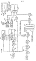
- FIG. 1 illustrates a system 10 embodying the present invention for monitoring operating conditions within a nuclear reactor comprising a nuclear reactor vessel 12 having a reactor core 14 contained therein.
- the system 10 includes a power peaking margin display system 16 and a visual display 18.
- a plurality of control rods 20 is received within the core 14 and regulate the reaction which occurs therein.
- the position of each control rod 20 is monitored by a position indicator 22, resulting in an output indicative of the reactivity regulating rod (RI) and the axial power shaping rod (ASPR) positions, both of which form separate inputs to the power peaking margin display system 16.
- a string of detectors 24 is provided within the core 14 for monitoring the power conditions therein.
- Output signals of the detectors 24 are brought out of the core 14, through the pressure boundary, and form an input to the power peaking margin display system 16.
- An ex-core detector 26 is provided to measure the neutron flux outside the core 14.
- An output signal of the detector 26 forms another input to the power peaking margin display system 16.
- the power peaking margin display system 16 is schematically illustrated in Figure 2.
- the signal produced by each incore detector 24 is adjusted by a factor (Y) by an adjustment circuit 30 to produce a signal representative of the power in the region of that specific detector relative to the power produced in all of the other areas in the reactor core 14.
- the output of the adjustment circuit 30 is representative of the relative power density (RPD) within the core 14.
- RPD relative power density
- the signal produced by the ex-core detector 26 is adjusted by an adjustment -circuit 32 to produce a signal representative of the fraction of rated power (FOP) that the core 14 is producing.
- a multiplier 34 is provided for multiplying this latter signal by the signal - produced by the adjustment circuit 30, i.e., the signal representative of the relative power density within the core 14, to produce a signal that is indicative of the power peak of the core.
- This latter signal is adjusted by an adjustment circuit 36 to account for system measurement and observation errors and to produce an adjusted power peak of the core.
- This adjusted power peak is compared to limiting criteria by a divider 38 which divides the adjusted power peak by the limiting criteria and subtracts the result from unity.
- the resulting output of the divider 38 is called the peaking margin and indicates the relative difference between the adjusted power peak and the limiting criteria.
- the foregoing is repeated for each of the incore detectors 24 and the resulting peaking margins are compared by a comparator 40 to determine the minimum margin for the core 14.
- a base, precalculated minimum margin is determined from measured core conditions by a function generator 42.
- Inputs to the function generator 42 include the signal representative of the fraction.of rated power (FOP) that the core is producing, the burnup calculated from the fraction of rated power (FOP) by means of an integrator 44 and a scaling circuit 46, and the xenon concentration calculated by another function generator 48 from the time behavior of the fraction of rated power (FOP).
- the foregoing minimum margin produced by the comparator 40 is compared to the base, pre-calculated minimum margin by a divider 50 which divides the minimum margin by the base, pre-calculated minimum margin producing an output signal representative of the amount of adjustment required to the limiting peaking margin line because of the differences due to xenon concentration, burnup..etc.
- This output signal which is in analog form, is converted to digital form by means of an analog to digital converter 52, and the resulting digital signal is used as an address to a limiting line pixel set contained within a memory 54.
- Another input to the memory 54 is the signal representative of the fraction of rated power (FOP) converted into digital form by means of an analog to digital converter 56. This input is also used to address the limiting line pixel set.
- the remaining inputs to the memory 54 are generated by an oscillator 58 and a plurality of counters 60, 62, the former counter defining the number of pixels per line and the latter counter defining the number of lines per frame.
- the visual display 18 is derived from the pixels defining the limiting margin line and from the reactivity regulating rod (RI) and the axial power shaping rod (ASPR) positions determined by the position indicator 22.
- the pixels defining the limiting margin line are retrieved from the memory 54 which is addressed by the pixel and line numbers generated by the oscillator 58 and the counters 60, 62, along with the digital signals representative of the fraction of power (FOP) and the required xenon concentration and burnup adjustments. In this manner the resulting margin line is developed by a plurality of interacting operating - parameters.
- the graph which is typically shown on the visual display 18 is illustrated.
- the axial power shaping rod position is plotted against the regulating rod position, both of these measurements being obtainable from the position indicator 22.
- the limiting line is-shown as Line "A" and divides the graph into a permissible operating area and a restricted operating area.
- the permissible operating area is further divided into a recommended operating area.
- the entire permissible area is available for transient conditions and the recommended operating area is used for steady state conditions.
- a cursor is utilized to indicate to the plant operator the present operating location of the core on the graph.
- this visual display eliminates the need for separate technical specification requirements for the following parameters inasmuch as they are accounted for in the display:
Abstract
Description
- This invention relates to systems for monitoring operating conditions within nuclear reactors.
- The monitoring of the core power level and the power distribution within the core of a nuclear reactor is done to prevent exceeding the applicable limiting criteria relative to heat generation. These power peaking or linear heat rate limits are preserved by monitoring pre-calculated limits for the parameters affecting power distribution (such as regulating rod and axial power shaping rod position), pre-calculated limits for the parameters indicating power distribution (such as axial power imbalance), or by directly measuring the actual peak on a regular basis and comparing it to a pre- calculated peaking limit. Present monitoring systems require collecting the information to be monitored from either several panel meters or a computer printout. This collection of information is sometimes automated to a degree by several computer alarms indicating which parameter is outside the allowable limit. This approach, however, does not provide information relative to the interaction between the various monitored parameters nor does it necessarily make clear the possible remedial actions when the parameter limits are exceeded.
- According to the present invention there is provided a system for monitoring operating conditions within a nuclear reactor, the system being characterised by means for measuring a plurality of operating parameters within the nuclear reactor, means for determining from said operating parameters the operating limits before a power peaking condition exists within the nuclear reactor, and means for displaying said operating limits, the means for displaying comprising a visual display permitting continuous monitoring of the operating conditions within the nuclear reactor.
- A preferred system embodying the invention and described hereinbelow illustrates the interaction between the various parameters that affect the power distribution within the core and shows the margin to the limiting operational criteria. The margin to the limiting criteria is displayed to the plant operator in a manner which shows the interaction between the various parameters that affect core power distribution. The preferred system solves or at least alleviates the aforementioned problems associated with the prior art by integrating data into a form that can be displayed so as to show the status of the core to the plant operator. This is accomplished by utilizing an incore monitoring system to furnish detector signals indicating power peaking data which are converted to relative power densities for subsequent comparison to the limiting criteria. The margin at the present operating conditions is then compared to a base margin for the purpose of adjusting the zero margin line. The present operating conditions and the adjusted zero margin line are then displayed to provide the relative operating margin to the limiting criteria. In this manner the resulting display shows the interaction between the various parameters that affect core power distribution and their effect on the margin to the limiting criteria.. In the event of a pending or actual violation of these limiting criteria, this display makes remedial action apparent to the plant operator.
- The invention will now be further described, by way of illustrative and non-limiting example, with reference to the accompanying drawings, in which:
- Figure 1 is a schematic view of a preferred system embodying the present invention;
- Figure 2 is an electrical schematic of circuitry utilized by a power peaking margin display portion of the system of Figure 1; and
- Figure 3 is a graph of axial power shaping rod position versus regulating rod position showing a limit line with respect to core operating parameters and resulting areas of permissible core operation.
- Figure 1 illustrates a
system 10 embodying the present invention for monitoring operating conditions within a nuclear reactor comprising anuclear reactor vessel 12 having areactor core 14 contained therein. Thesystem 10 includes a power peakingmargin display system 16 and avisual display 18. A plurality ofcontrol rods 20 is received within thecore 14 and regulate the reaction which occurs therein. The position of eachcontrol rod 20 is monitored by aposition indicator 22, resulting in an output indicative of the reactivity regulating rod (RI) and the axial power shaping rod (ASPR) positions, both of which form separate inputs to the power peakingmargin display system 16. A string ofdetectors 24 is provided within thecore 14 for monitoring the power conditions therein. Output signals of thedetectors 24 are brought out of thecore 14, through the pressure boundary, and form an input to the power peakingmargin display system 16. Anex-core detector 26 is provided to measure the neutron flux outside thecore 14. An output signal of thedetector 26 forms another input to the power peakingmargin display system 16. - The power peaking
margin display system 16 is schematically illustrated in Figure 2. The signal produced by eachincore detector 24 is adjusted by a factor (Y) by anadjustment circuit 30 to produce a signal representative of the power in the region of that specific detector relative to the power produced in all of the other areas in thereactor core 14. Thus, the output of theadjustment circuit 30 is representative of the relative power density (RPD) within thecore 14. While the foregoing is occurring, the signal produced by theex-core detector 26 is adjusted by an adjustment -circuit 32 to produce a signal representative of the fraction of rated power (FOP) that thecore 14 is producing. Amultiplier 34 is provided for multiplying this latter signal by the signal - produced by theadjustment circuit 30, i.e., the signal representative of the relative power density within thecore 14, to produce a signal that is indicative of the power peak of the core. This latter signal is adjusted by anadjustment circuit 36 to account for system measurement and observation errors and to produce an adjusted power peak of the core. This adjusted power peak is compared to limiting criteria by adivider 38 which divides the adjusted power peak by the limiting criteria and subtracts the result from unity. The resulting output of thedivider 38 is called the peaking margin and indicates the relative difference between the adjusted power peak and the limiting criteria. The foregoing is repeated for each of theincore detectors 24 and the resulting peaking margins are compared by acomparator 40 to determine the minimum margin for thecore 14. - A base, precalculated minimum margin is determined from measured core conditions by a function generator 42. Inputs to the function generator 42 include the signal representative of the fraction.of rated power (FOP) that the core is producing, the burnup calculated from the fraction of rated power (FOP) by means of an
integrator 44 and ascaling circuit 46, and the xenon concentration calculated by anotherfunction generator 48 from the time behavior of the fraction of rated power (FOP). - The foregoing minimum margin produced by the
comparator 40 is compared to the base, pre-calculated minimum margin by adivider 50 which divides the minimum margin by the base, pre-calculated minimum margin producing an output signal representative of the amount of adjustment required to the limiting peaking margin line because of the differences due to xenon concentration, burnup..etc. This output signal, which is in analog form, is converted to digital form by means of an analog todigital converter 52, and the resulting digital signal is used as an address to a limiting line pixel set contained within amemory 54. Another input to thememory 54 is the signal representative of the fraction of rated power (FOP) converted into digital form by means of an analog todigital converter 56. This input is also used to address the limiting line pixel set. The remaining inputs to thememory 54 are generated by anoscillator 58 and a plurality ofcounters - The
visual display 18 is derived from the pixels defining the limiting margin line and from the reactivity regulating rod (RI) and the axial power shaping rod (ASPR) positions determined by theposition indicator 22. The pixels defining the limiting margin line are retrieved from thememory 54 which is addressed by the pixel and line numbers generated by theoscillator 58 and thecounters - Referring now to Figure 3, the graph which is typically shown on the
visual display 18 is illustrated. In this graph, the axial power shaping rod position is plotted against the regulating rod position, both of these measurements being obtainable from theposition indicator 22. The limiting line is-shown as Line "A" and divides the graph into a permissible operating area and a restricted operating area. The permissible operating area is further divided into a recommended operating area. The entire permissible area is available for transient conditions and the recommended operating area is used for steady state conditions. A cursor is utilized to indicate to the plant operator the present operating location of the core on the graph. - From the foregoing, it is apparent that in the event of a core change resulting in the convergence of the limiting line and the cursor, the plant operator can easily see from the display what corrective action must be taken, i.e., he will either move the axial power shaping rods or the regulating rods. The
visual display 18 clearly shows which rods must be moved and the direction in which they must be moved in order to direct the cursor back into the permissible operating area. The display eliminates any confusion as to which action must be taken to correct a potential problem. - In addition to immediately alerting the plant operator of a core change requiring corrective action and the action which must be taken, this visual display eliminates the need for separate technical specification requirements for the following parameters inasmuch as they are accounted for in the display:
- a) Regulating Rods versus Power Level;
- b) Operational Imbalance Envelope;
- c) Quadrant Power Tilt; and
- d) Axial Power Shaping Rod versus Power Level.
- Thus, the need for the plant operator'to consult three separate graphs and to compute the quadrant power tilt has been eliminated by this visual display, and he can respond quickly to any significant core change.
Claims (6)
Applications Claiming Priority (2)
| Application Number | Priority Date | Filing Date | Title |
|---|---|---|---|
| US402185 | 1982-07-26 | ||
| US06/402,185 US4568513A (en) | 1982-07-26 | 1982-07-26 | Reactor power peaking information display |
Publications (2)
| Publication Number | Publication Date |
|---|---|
| EP0100640A1 true EP0100640A1 (en) | 1984-02-15 |
| EP0100640B1 EP0100640B1 (en) | 1986-12-30 |
Family
ID=23590874
Family Applications (1)
| Application Number | Title | Priority Date | Filing Date |
|---|---|---|---|
| EP83304288A Expired EP0100640B1 (en) | 1982-07-26 | 1983-07-25 | Systems for monitoring operating conditions within nuclear reactors |
Country Status (7)
| Country | Link |
|---|---|
| US (1) | US4568513A (en) |
| EP (1) | EP0100640B1 (en) |
| JP (1) | JPS5934195A (en) |
| KR (1) | KR900006010B1 (en) |
| CA (1) | CA1210532A (en) |
| DE (1) | DE3368798D1 (en) |
| ES (1) | ES8608719A1 (en) |
Cited By (7)
| Publication number | Priority date | Publication date | Assignee | Title |
|---|---|---|---|---|
| US4552718A (en) * | 1982-07-01 | 1985-11-12 | Westinghouse Electric Corp. | Method and apparatus for on-line monitoring of the operation of a complex non-linear process control system |
| US4568513A (en) * | 1982-07-26 | 1986-02-04 | The Babcock & Wilcox Company | Reactor power peaking information display |
| FR2610446A1 (en) * | 1987-01-30 | 1988-08-05 | Framatome Sa | METHOD FOR DETERMINING THE CRITICAL WARMING ALARM THRESHOLD THRESHOLD, DEVICE FOR CARRYING OUT THE METHOD, AND METHOD FOR CONTROLLING A NUCLEAR REACTOR |
| WO1997030382A1 (en) * | 1996-02-13 | 1997-08-21 | Westinghouse Electric Corporation | Apparatus and method for monitoring pressure-temperature margins |
| EP1457867A1 (en) * | 2003-03-14 | 2004-09-15 | Koninklijke Philips Electronics N.V. | System for adjusting a combination of control parameters |
| EP1496426A2 (en) * | 2003-07-11 | 2005-01-12 | Siemens Aktiengesellschaft | Method for the inputting of parameters of a parameter field |
| RU2470392C1 (en) * | 2011-06-28 | 2012-12-20 | Федеральное государственное бюджетное учреждение "Национальный исследовательский центр "Курчатовский институт" | Method of controlling nuclear reactor |
Families Citing this family (7)
| Publication number | Priority date | Publication date | Assignee | Title |
|---|---|---|---|---|
| US4816208A (en) * | 1986-02-14 | 1989-03-28 | Westinghouse Electric Corp. | Alarm management system |
| US4774050A (en) * | 1986-04-10 | 1988-09-27 | Westinghouse Electric Corp. | Axial power distribution monitor and display using outputs from ex-core detectors and thermocouples |
| US4853175A (en) * | 1988-03-10 | 1989-08-01 | The Babcock & Wilcox Company | Power plant interactive display |
| US4927594A (en) * | 1988-08-10 | 1990-05-22 | Westinghouse Electric Corp. | Thermocouple based control rod position indication system |
| US4965040A (en) * | 1989-04-13 | 1990-10-23 | The Babcock & Wilcox Company | Maximum/minimum asymmetric rod detection |
| US5167010A (en) * | 1989-08-03 | 1992-11-24 | Westinghouse Electric Corp. | Expert advice display processing system |
| JP2936810B2 (en) * | 1991-06-28 | 1999-08-23 | 住友電気工業株式会社 | Foam heat shrink tubing |
Citations (4)
| Publication number | Priority date | Publication date | Assignee | Title |
|---|---|---|---|---|
| US3079315A (en) * | 1957-05-16 | 1963-02-26 | Commissariat Energie Atomique | Nuclear reactor control |
| US3565760A (en) * | 1967-10-23 | 1971-02-23 | Gen Electric | Nuclear reactor power monitor system |
| GB1244965A (en) * | 1967-12-29 | 1971-09-02 | British Nuclear Design Constr | Nuclear reactor control system |
| US4016034A (en) | 1974-07-19 | 1977-04-05 | Combustion Engineering, Inc. | Nuclear reactor control override system and method |
Family Cites Families (6)
| Publication number | Priority date | Publication date | Assignee | Title |
|---|---|---|---|---|
| US3998693A (en) * | 1970-11-23 | 1976-12-21 | Combustion Engineering, Inc. | Thermal margin control |
| US3873817A (en) * | 1972-05-03 | 1975-03-25 | Westinghouse Electric Corp | On-line monitoring of steam turbine performance |
| US4080251A (en) * | 1973-05-22 | 1978-03-21 | Combustion Engineering, Inc. | Apparatus and method for controlling a nuclear reactor |
| US4079236A (en) * | 1976-03-05 | 1978-03-14 | Westinghouse Electric Corporation | Method and apparatus for monitoring the axial power distribution within the core of a nuclear reactor, exterior of the reactor |
| JPS5684592A (en) * | 1979-12-14 | 1981-07-09 | Hitachi Ltd | Inncore monitoring device |
| US4568513A (en) * | 1982-07-26 | 1986-02-04 | The Babcock & Wilcox Company | Reactor power peaking information display |
-
1982
- 1982-07-26 US US06/402,185 patent/US4568513A/en not_active Expired - Lifetime
-
1983
- 1983-07-08 KR KR1019830003120A patent/KR900006010B1/en not_active IP Right Cessation
- 1983-07-09 ES ES523996A patent/ES8608719A1/en not_active Expired
- 1983-07-13 CA CA000432354A patent/CA1210532A/en not_active Expired
- 1983-07-25 EP EP83304288A patent/EP0100640B1/en not_active Expired
- 1983-07-25 DE DE8383304288T patent/DE3368798D1/en not_active Expired
- 1983-07-26 JP JP58135281A patent/JPS5934195A/en active Granted
Patent Citations (4)
| Publication number | Priority date | Publication date | Assignee | Title |
|---|---|---|---|---|
| US3079315A (en) * | 1957-05-16 | 1963-02-26 | Commissariat Energie Atomique | Nuclear reactor control |
| US3565760A (en) * | 1967-10-23 | 1971-02-23 | Gen Electric | Nuclear reactor power monitor system |
| GB1244965A (en) * | 1967-12-29 | 1971-09-02 | British Nuclear Design Constr | Nuclear reactor control system |
| US4016034A (en) | 1974-07-19 | 1977-04-05 | Combustion Engineering, Inc. | Nuclear reactor control override system and method |
Non-Patent Citations (2)
| Title |
|---|
| NUCLEAR TECHNOLOGY, vol. 58, no. 1, July 1982, pages 9-21, Danville, Illinois, USA * |
| Y. NISHIZAWA ET AL., NUCLEAR TECHNOLOGY, vol. 58, July 1982 (1982-07-01), pages 9 - 22 |
Cited By (12)
| Publication number | Priority date | Publication date | Assignee | Title |
|---|---|---|---|---|
| US4552718A (en) * | 1982-07-01 | 1985-11-12 | Westinghouse Electric Corp. | Method and apparatus for on-line monitoring of the operation of a complex non-linear process control system |
| US4568513A (en) * | 1982-07-26 | 1986-02-04 | The Babcock & Wilcox Company | Reactor power peaking information display |
| FR2610446A1 (en) * | 1987-01-30 | 1988-08-05 | Framatome Sa | METHOD FOR DETERMINING THE CRITICAL WARMING ALARM THRESHOLD THRESHOLD, DEVICE FOR CARRYING OUT THE METHOD, AND METHOD FOR CONTROLLING A NUCLEAR REACTOR |
| EP0277594A1 (en) * | 1987-01-30 | 1988-08-10 | Framatome | Method of determining the alarm level of the critical heat-up and device for carrying it out. |
| US4836973A (en) * | 1987-01-30 | 1989-06-06 | Framatome | Method of determining the alarm threshold of the over-heating ratio, a device for implementing the method, and a method of controlling a nuclear reactor |
| WO1997030382A1 (en) * | 1996-02-13 | 1997-08-21 | Westinghouse Electric Corporation | Apparatus and method for monitoring pressure-temperature margins |
| EP1457867A1 (en) * | 2003-03-14 | 2004-09-15 | Koninklijke Philips Electronics N.V. | System for adjusting a combination of control parameters |
| WO2004081782A1 (en) * | 2003-03-14 | 2004-09-23 | Koninklijke Philips Electronics N.V. | System for adjusting a combination of control parameters |
| US8938676B2 (en) | 2003-03-14 | 2015-01-20 | Koninklijke Philips N.V. | System for adjusting a combination of control parameters |
| EP1496426A2 (en) * | 2003-07-11 | 2005-01-12 | Siemens Aktiengesellschaft | Method for the inputting of parameters of a parameter field |
| EP1496426A3 (en) * | 2003-07-11 | 2006-09-20 | Siemens Aktiengesellschaft | Method for the inputting of parameters of a parameter field |
| RU2470392C1 (en) * | 2011-06-28 | 2012-12-20 | Федеральное государственное бюджетное учреждение "Национальный исследовательский центр "Курчатовский институт" | Method of controlling nuclear reactor |
Also Published As
| Publication number | Publication date |
|---|---|
| CA1210532A (en) | 1986-08-26 |
| KR840005595A (en) | 1984-11-14 |
| DE3368798D1 (en) | 1987-02-05 |
| JPH0374355B2 (en) | 1991-11-26 |
| ES523996A0 (en) | 1986-07-16 |
| US4568513A (en) | 1986-02-04 |
| EP0100640B1 (en) | 1986-12-30 |
| JPS5934195A (en) | 1984-02-24 |
| KR900006010B1 (en) | 1990-08-20 |
| ES8608719A1 (en) | 1986-07-16 |
Similar Documents
| Publication | Publication Date | Title |
|---|---|---|
| US4568513A (en) | Reactor power peaking information display | |
| US6430247B1 (en) | Method and system for monitoring at least one operating parameter of the core of a nuclear reactor | |
| CA1079419A (en) | Method and apparatus for monitoring the axial power distribution within the core of a nuclear reactor, exterior of the reactor | |
| EP0241301A2 (en) | Axial power distribution monitor and display using outputs from ex-core detectors and thermocouples | |
| JPS62245997A (en) | Sensor monitor device displaying profile of monitor parameter | |
| JP2628534B2 (en) | Method and apparatus for synthesizing continuous power distribution of reactor core | |
| US6236699B1 (en) | Method and system for monitoring control rod element assembly position | |
| US6400786B1 (en) | Process and device for monitoring at least one operating parameter of the core of a nuclear reactor | |
| US6493412B1 (en) | Method of calibrating exit thermocouples in a nuclear reactor | |
| JPH068890B2 (en) | Core performance calculator | |
| JPS59193398A (en) | Reactor power distribution monitoring device | |
| JPH07128484A (en) | Operation monitoring and protection method for reactor | |
| Mesquita et al. | A human-machine interface for a Triga research reactor of Brazil | |
| JP2975654B2 (en) | Core monitoring device | |
| US6353650B1 (en) | Reduced in-core instrument patterns for pressurized water reactors | |
| Karim et al. | Development of a central PC-based system for reactor signal monitoring and analysis | |
| Bevilacqua et al. | Application of Digital Computer Systems in Nuclear Power Plants | |
| JPH0219918B2 (en) | ||
| JPH04315995A (en) | Nuclear reactor output monitoring device | |
| JPS60219589A (en) | Method and device for monitoring partial output peaking coefficient | |
| JPS6337916B2 (en) | ||
| JPS63169599A (en) | Output distribution monitor for nuclear reactor | |
| JPS61213690A (en) | Monitor device for distribution of output from nuclear reactor | |
| JPS60120289A (en) | Neutron detector | |
| Mummery et al. | The PFR station control system |
Legal Events
| Date | Code | Title | Description |
|---|---|---|---|
| PUAI | Public reference made under article 153(3) epc to a published international application that has entered the european phase |
Free format text: ORIGINAL CODE: 0009012 |
|
| AK | Designated contracting states |
Designated state(s): CH DE FR GB IT LI |
|
| 17P | Request for examination filed |
Effective date: 19840719 |
|
| ITF | It: translation for a ep patent filed |
Owner name: ST. ASSOC. MARIETTI & PIPPARELLI |
|
| GRAA | (expected) grant |
Free format text: ORIGINAL CODE: 0009210 |
|
| AK | Designated contracting states |
Kind code of ref document: B1 Designated state(s): CH DE FR GB IT LI |
|
| REF | Corresponds to: |
Ref document number: 3368798 Country of ref document: DE Date of ref document: 19870205 |
|
| ET | Fr: translation filed | ||
| PLBI | Opposition filed |
Free format text: ORIGINAL CODE: 0009260 |
|
| 26 | Opposition filed |
Opponent name: SIEMENS AKTIENGESELLSCHAFT, BERLIN UND MUENCHEN Effective date: 19870930 |
|
| REG | Reference to a national code |
Ref country code: CH Ref legal event code: PL |
|
| GBPC | Gb: european patent ceased through non-payment of renewal fee | ||
| REG | Reference to a national code |
Ref country code: GB Ref legal event code: 728C |
|
| REG | Reference to a national code |
Ref country code: GB Ref legal event code: 728A |
|
| PG25 | Lapsed in a contracting state [announced via postgrant information from national office to epo] |
Ref country code: LI Free format text: LAPSE BECAUSE OF NON-PAYMENT OF DUE FEES Effective date: 19890731 Ref country code: CH Free format text: LAPSE BECAUSE OF NON-PAYMENT OF DUE FEES Effective date: 19890731 |
|
| ITTA | It: last paid annual fee | ||
| PLBN | Opposition rejected |
Free format text: ORIGINAL CODE: 0009273 |
|
| STAA | Information on the status of an ep patent application or granted ep patent |
Free format text: STATUS: OPPOSITION REJECTED |
|
| 27O | Opposition rejected |
Effective date: 19930210 |
|
| PGFP | Annual fee paid to national office [announced via postgrant information from national office to epo] |
Ref country code: FR Payment date: 19980618 Year of fee payment: 16 |
|
| PGFP | Annual fee paid to national office [announced via postgrant information from national office to epo] |
Ref country code: DE Payment date: 19980625 Year of fee payment: 16 |
|
| PGFP | Annual fee paid to national office [announced via postgrant information from national office to epo] |
Ref country code: GB Payment date: 19980626 Year of fee payment: 16 |
|
| PG25 | Lapsed in a contracting state [announced via postgrant information from national office to epo] |
Ref country code: GB Free format text: LAPSE BECAUSE OF NON-PAYMENT OF DUE FEES Effective date: 19990725 |
|
| PG25 | Lapsed in a contracting state [announced via postgrant information from national office to epo] |
Ref country code: FR Free format text: THE PATENT HAS BEEN ANNULLED BY A DECISION OF A NATIONAL AUTHORITY Effective date: 19990731 |
|
| GBPC | Gb: european patent ceased through non-payment of renewal fee |
Effective date: 19990725 |
|
| PG25 | Lapsed in a contracting state [announced via postgrant information from national office to epo] |
Ref country code: DE Free format text: LAPSE BECAUSE OF NON-PAYMENT OF DUE FEES Effective date: 20000503 |
|
| REG | Reference to a national code |
Ref country code: FR Ref legal event code: ST |
|
| APAH | Appeal reference modified |
Free format text: ORIGINAL CODE: EPIDOSCREFNO |