EP0100636A1 - Toe lasting machine with adjustable heel clamp pad - Google Patents
Toe lasting machine with adjustable heel clamp pad Download PDFInfo
- Publication number
- EP0100636A1 EP0100636A1 EP83304278A EP83304278A EP0100636A1 EP 0100636 A1 EP0100636 A1 EP 0100636A1 EP 83304278 A EP83304278 A EP 83304278A EP 83304278 A EP83304278 A EP 83304278A EP 0100636 A1 EP0100636 A1 EP 0100636A1
- Authority
- EP
- European Patent Office
- Prior art keywords
- insole
- shoe assembly
- slide
- heel
- wiping
- Prior art date
- Legal status (The legal status is an assumption and is not a legal conclusion. Google has not performed a legal analysis and makes no representation as to the accuracy of the status listed.)
- Granted
Links
- 230000002045 lasting effect Effects 0.000 title claims abstract description 7
- 210000000080 chela (arthropods) Anatomy 0.000 claims description 12
- 239000011435 rock Substances 0.000 claims description 3
- 239000000853 adhesive Substances 0.000 description 7
- 230000001070 adhesive effect Effects 0.000 description 7
- 238000010276 construction Methods 0.000 description 2
- VRDIULHPQTYCLN-UHFFFAOYSA-N Prothionamide Chemical compound CCCC1=CC(C(N)=S)=CC=N1 VRDIULHPQTYCLN-UHFFFAOYSA-N 0.000 description 1
- 230000000712 assembly Effects 0.000 description 1
- 238000000429 assembly Methods 0.000 description 1
- 230000001419 dependent effect Effects 0.000 description 1
- 238000001125 extrusion Methods 0.000 description 1
- 229910000078 germane Inorganic materials 0.000 description 1
- 230000037303 wrinkles Effects 0.000 description 1
Images


Classifications
-
- A—HUMAN NECESSITIES
- A43—FOOTWEAR
- A43D—MACHINES, TOOLS, EQUIPMENT OR METHODS FOR MANUFACTURING OR REPAIRING FOOTWEAR
- A43D23/00—Single parts for pulling-over or lasting machines
-
- A—HUMAN NECESSITIES
- A43—FOOTWEAR
- A43D—MACHINES, TOOLS, EQUIPMENT OR METHODS FOR MANUFACTURING OR REPAIRING FOOTWEAR
- A43D21/00—Lasting machines
- A43D21/12—Lasting machines with lasting clamps, shoe-shaped clamps, pincers, wipers, stretching straps or the like for forming the toe or heel parts of the last
Definitions
- the present invention relates to toe lasting machines in which there is provided an adjustable heel clamp.
- U.S. Patent Re. 26,860 shows a.toe lasting machine operable on a shoe assembly formed of a last having an upper draped thereon and an insole secured to its bottom to wipe the toe portion of the margin of the upper against the corresponding portion of the insole.
- This machine comprises wiping means mounted for forward and inward movement in a wiping stroke from a retracted position in a wiping plane to wipe the toe portion of the upper margin against the insole; an insole rest, located forwardly of the wiping means in its retracted position, mounted for heightwise movement, so supporting the shoe assembly with the toe portion of the shoe assembly facing rearwardly that the toe portion of the insole bottom is inclined upwardly in a heelward and forward direction relative to the wiping plane after the toe portion of the upper has been stretched about the vamp of the last pursuant to relative upward movement of the insole rest with respect to pincers gripping the toe portion of the upper margin; a heel clamp pad, mounted for movement in forward-rearward directions, located forwardly of the insole rest and engagable, pursuant to its rearward movement, with the heel end of the shoe assembly; a slide mounted for heightwise substantially upward and downward movement; spring means yieldably urging the slide upwardly; connecting means connecting the heel clamp pad to the slide for heightwise movement therewith
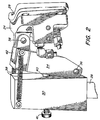
- Figure 1 shows the toe lasting machine 10 that, except for the heel clamp, is of conventional construction in accordance, for example with the disclosures of US Patents Re. 26,860 and Re. 29.069 (granted 14th December, 1976).
- the operator is intended to stand in front of the machine 10 as seen in figure 1 and a direction extending towards the operator will be referred to as forward while a direction extending away from the operator will be referred to as rearward.
- the machine 10 is inclined for ease of presentation of shoe assemblies thereto and convenience of operation.
- the machine includes substantially flat wipers 12 that are therefore inclined from the horizontal.
- a direction lying substantially in the plane of the wipers 12 will be referred to as horizontal and a direction at right angles to the plane of the wipers 12 will be referred to as vertical.
- the machine 10 has an insole rest 14 mounted for heightwise; movement an adhesive applicator 16 located outwardly of the insole rest 14 mounted for heightwise movement; the wipers 12 located rearwardly of the insole rest mounted for planar forward and inward movement; a U-shaped yoke 18 located above the level of the wipers 12 rearwardly of the insole rest having a pair of forwardly divergent legs; a plurality of pincers 20 extending rearwardly of and laterally about the insole rest -14 and the adhesive extruder 16 having jaws movable between open and closed positions; a toe hold-down 22 movable from the lateral out-of-the-way position shown in figure 1 to a working position above the .insole rest 14 and movable heightwise towards and away from the insole rest 14; and a heel clamp 24, mounted to a cross-bar 26 by a post 28, located forwardly of the insole rest 14 for movement towards and away from the insole rest 14.
- a heel pad 29 is mounted to the back of the heel
- a block 30 is movably mounted to the post 28 to be set in a desired heightwise position on the post 28 by manipulation, in a manner not shown, of a knob 32 threaded into the block 30.
- the bottom of an arm 34 is pivoted to the block 30 on a pivot pin 36 for swinging forward rearward movement towards and away from the insole rest ' 14 about the axis of the pin 36.
- Springs 38 extending between the block 30 and the arm 34, yieldably urge the arm 34 forwardly about the axis of the pin 36 to an adjusted position determined by the engagement of the arm 34 with a bolt 40 that is threaded into the block 30 and that is manipulable by a knob-41.
- a slide 42 is mounted in the arm 34 f orheightwise movement by rolls 44 on the slide 42 being movable between flanges 46 and 48 of the arm 34.
- a spring 50 interposed between the bottom of the slide 42 and a lug 52 on the arm 34 yieldably urges the slide 42 upwardly to a position wherein a pin 54 on the arm 34 riding in a slot 56 in the slide 42 engages the bottom of the slot 56.
- the heel clamp 24 is pivoted to the top of the slide 42 by a pin 58 for forward rearward swinging movement towards and away from the insole rest 14.
- a stud 60 is interposed between the heel clamp 24 and the slide 42 with the front of the stud 60 being threaded into the slide 42 and the back of the stud 60 being movably mounted in a cut-out 62 in the heel clamp 24. Therefore, the position of the heel clamp 24 with respect to the slide 42 may be adjusted about the axis of the pin 58 by rotating the stud.60 by a knob 64 affixed to the stud 60.
- the insole rest 14 and the adhesive extruder 16 are in lower positions with their tops below the level of the tops of the wipers 12; the wipers 12 and the yoke 18 are in rearward retracted positions; the jaws of the pincers '20 are open; the toe hold-down 22 is in its upper position; and the heel clamp 24 is in a forward position.
- a shoe assembly 66 formed of a last 68 having an upper 70 draped thereon and an insole 72 secured to its bottom, is presented to the machine 10.
- the forepart of the shoe assembly bottom is supported on the insole rest 14 with the toe end of the shoe assembly facing rearwardly towards the wipers 12.
- the shoe assembly is so placed on the insole rest 14 that the bottom of the toe portion of the insole 72 is inclined upwardly and forwardly or heelwardly relative to the insole rest 14 and while in this position the upper margin 74 is placed between the open jaws of all of the pincers 20.
- the upward and heelward inclination of the bottom of the forepart of the insole 72 facilitates the placement of the upper margin 74.between the open jaws of the rearmost pincers 20 that receive the toe end extremity of the upper margin.
- the heel clamp 24 is moved rearwardly to cause the heel pad 29 _to engage the heel end of the upper 70 of the shoe assembly 66, as shown in figure 6.
- the knob 32 Prior to the presentation of the shoe assembly 66 to the machine 10, the knob 32 has been manipulated to bring the heel pad 29 to a height corresponding to the height of the heel portion of the upper 70, this height being dependent on the heel height of the shoe assembly 66.
- the knob 41 was so manipulated to swing the arm 34 about the pin 36 as to bring the heel pad 29 to a plane that is parallel to the tangent of the curved heel portion of the last 68 and the upper 70 and the knob 64 was so manipulated to so swing the heel clamp 24 about the pin 58 as to cause the heel pad 29 to movevertically (ie dowswand) pursuant to vertical movement of the slide 42 in a plane parallel tothe tangent of the curved heel portion of the last 68 and of the upper 70.
- the wipers 12 and the yoke 18 are now caused to move forwardly for example by mechanism such as that shown in US Patent 3397417, to bring them to the figure 6 position wherein the wipers 12 are adjacent the shoe assembly 66 in readiness for wiping and the yoke l8.is clamping the toe portion of the upper 70 against the last 68.
- This is followed, for example in the manner shown in US Patent RE. 26860, by a lowering of the toe hold down 22 against the top of the vamp of the shoe assembly 66, under relatively low pressure, to clamp the shoe assembly between the insole rest 14 and the toe hold down 22.
- the wipers 12 are caused to move forwardly and inwardly in a wiping stroke to engage the toe portion of the upper margin 74 and wipe or fold.the toe portion of the upper margin inwardly against the insole 72 to thereby bond the toe portion of the upper margin to the insole by way of the adhesive that has been extruded against i the insole.
- the pincers 20 and the insole rest 14 are lowered out of the path of the oncoming wipers and the toe ho Id down 22 is forced downwardly under relatively high bedding pressure to apply increased pressure of the bottom of the shoe assembly 66 against the flat tops of the wipers 12. With the lowering of the insole rest and the application of the bedding pressure, the toe portion of the bottom of the shoe assembly 66 is supported solely by the wipers 12.
- the application of the pressure by the toe hold-down 22 causes the bottom of the toe portion of the insole 72 to be pressed flat against the insole rest 14 or the wipers 12 to thereby lower the heel end of the shoe assembly 66 while the heel end of the shoe assembly is being clamped by the heel clamp pad 29.
- the lowering of the heel end of the shoe assembly 66 enables the slide 42 to lower together with the heel pad 29 against the yieldable upwardly directed force of the spring 50.
- the heel clamp pad 29 stays substantially in the plane parallel to the tangent of the heel portion of the last 68 so that it continues to clamp against the heel portion of the shoe assembly 66 during this lowering without scuffing or marring the heel portion of the upper 70, without wrinkling the heel portion of the upper or disturbing the position of the heel protion of the upper on the last 68 and without binding against the heel portion of the shoe assembly 66.
- the toe lasting machine 10 is operable on the shoe assembly 66 formed of the last 68 having the upper 70 draped thereon and the insole 72 secured to its bottom to wipe the toe portion of the margin 74 of the upper against the corresponding portion of the insole.
- the machine comprises: wiping means formed of the wipers 12 that are mounted for forward and inward movement in a wiping stroke from a retracted position in a wiping plane formed by the top surfaces 76 ( Figure 6) of the wipers to wipe the top portion of the upper margin against the insole; the insole rest 14, located forwardly of the wiping means 12 in its retracted position, mounted for heightwise movement, so supporting the shoe assembly with the toe portion of the shoe assembly facing rearwardly that the toe portion of the insole bottom is inclined upwardly in a heelward and forward direction relative to the wiping plane after the toe portion of the upper has been stretched about the vamp of the last pursuant to relative upward movement of the insole rest with respect to the pincers 20 gripping the toe portion of the
- the machine further comprises the block 30 and the arm 34 pivoted to the block by the pin 36.
- the slide 42 is mounted for heighwise movement in the arm 34.
- the machine further comprises, the bolt 40 adjustably mounted to the block and bearing against the arm, and spring means, in the form of the springs 38, yieldably urging the arm 34 forwardly about the axis of the pin 36 against the bolt.
- the connecting means connecting the heel clamp pad 29 to the slide 42 comprises the pin 58 whose axis is parallel to the axis of the pin 36 pivotally mounting the heel clamp pad to the slide, and an adjusting device formed of the members 60, 62 and 64 for adjusting the angular position of the heel clamp pad with respect to the slide about the axis of the pin 58.
Landscapes
- Footwear And Its Accessory, Manufacturing Method And Apparatuses (AREA)
Abstract
Description
- The present invention relates to toe lasting machines in which there is provided an adjustable heel clamp.
- U.S. Patent Re. 26,860 (granted 21st April, 1970), shows a.toe lasting machine operable on a shoe assembly formed of a last having an upper draped thereon and an insole secured to its bottom to wipe the toe portion of the margin of the upper against the corresponding portion of the insole. This machine comprises wiping means mounted for forward and inward movement in a wiping stroke from a retracted position in a wiping plane to wipe the toe portion of the upper margin against the insole; an insole rest, located forwardly of the wiping means in its retracted position, mounted for heightwise movement, so supporting the shoe assembly with the toe portion of the shoe assembly facing rearwardly that the toe portion of the insole bottom is inclined upwardly in a heelward and forward direction relative to the wiping plane after the toe portion of the upper has been stretched about the vamp of the last pursuant to relative upward movement of the insole rest with respect to pincers gripping the toe portion of the upper margin; a heel clamp pad, mounted for movement in forward-rearward directions, located forwardly of the insole rest and engagable, pursuant to its rearward movement, with the heel end of the shoe assembly; a slide mounted for heightwise substantially upward and downward movement; spring means yieldably urging the slide upwardly; connecting means connecting the heel clamp pad to the slide for heightwise movement therewith; means for lowering the insole rest out of the path of movement of the wiping means during the wiping stroke to prevent engagement of the insole rest by the wiping means during the wiping stroke, and a toe hold-down, located above the insole rest, mounted for downward movement against the vamp of the shoe assembly to press against the vamp of the shoe assembly to clamp the shoe assembly between the toe hold-down and the insole rest prior to the lowering of the insole rest and to thereafter clamp the shoe assembly between the toe hold-down and the wiping means, the pressing of the toe hold-down against the vamp of the shoe assembly causing the heel end of the shoe assembly to rock downwardly until the insole is fully supported by the insole or the wiping means. During the downward rocking of the heel end of the shoe assembly, the heel clamp pad moves downwardly against the force of the spring means to enable the heel clamp pad to continue to engage the heel end of the shoe assembly without shifting with respect to the heel end of the shoe assembly.
- With the prior art machine as exemplified in US Patent Re. 26860 and as set forth in the preceding paragraph, problems of the heel clamp pad binding against the heel portion of the shoe assembly during the downward rocking of the heel portion of the shoe assembly developed. In addition, during the downward rocking movement, there was a tendency of the heel clamp pad to mar, scuff or wrinkle the heel portion of the upper and to shift the heel portion of the upper on the last.
- In accordance with this invention, these problems are alleviated by mounting the slide, together with the heel clamp pad, for forward-rearward swinging adjustment about an axis transverse to the forward rearward directions so that the heel clamp pad can be adjusted to be substantially in the plane parallel to the tangent of the heel portion of the last.
- One embodiment will now be described with reference to the accompanying drawings in which:
- Figure 1 is a front elevation view of a portion of the machine of this invention;
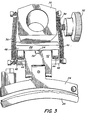
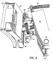
- Figures 2-5 are isometric views of a heel clamp mounting the heel clamp pad, the slide and the mechanism for effecting the swinging adjustment of the slide; and
- Figure 6 is a schematic representation of a shoe assembly as it appears in the machine immediately prior to the commencement of the wiping stroke.
- Figure 1 shows the
toe lasting machine 10 that, except for the heel clamp, is of conventional construction in accordance, for example with the disclosures of US Patents Re. 26,860 and Re. 29.069 (granted 14th December, 1976). The operator is intended to stand in front of themachine 10 as seen in figure 1 and a direction extending towards the operator will be referred to as forward while a direction extending away from the operator will be referred to as rearward. - The
machine 10 is inclined for ease of presentation of shoe assemblies thereto and convenience of operation. The machine includes substantiallyflat wipers 12 that are therefore inclined from the horizontal. However, for ease of explanation, a direction lying substantially in the plane of thewipers 12 will be referred to as horizontal and a direction at right angles to the plane of thewipers 12 will be referred to as vertical. - The
machine 10, as is conventional, has aninsole rest 14 mounted for heightwise; movement anadhesive applicator 16 located outwardly of theinsole rest 14 mounted for heightwise movement; thewipers 12 located rearwardly of the insole rest mounted for planar forward and inward movement; aU-shaped yoke 18 located above the level of thewipers 12 rearwardly of the insole rest having a pair of forwardly divergent legs; a plurality ofpincers 20 extending rearwardly of and laterally about the insole rest -14 and theadhesive extruder 16 having jaws movable between open and closed positions; a toe hold-down 22 movable from the lateral out-of-the-way position shown in figure 1 to a working position above the.insole rest 14 and movable heightwise towards and away from theinsole rest 14; and aheel clamp 24, mounted to across-bar 26 by apost 28, located forwardly of theinsole rest 14 for movement towards and away from theinsole rest 14. Aheel pad 29 is mounted to the back of theheel clamp 24. This invention is concerned with the construction and mounting of theheel clamp 24 and theheel pad 29. - Referring to figures 2-5, a
block 30 is movably mounted to thepost 28 to be set in a desired heightwise position on thepost 28 by manipulation, in a manner not shown, of aknob 32 threaded into theblock 30. The bottom of anarm 34 is pivoted to theblock 30 on apivot pin 36 for swinging forward rearward movement towards and away from theinsole rest '14 about the axis of thepin 36. Springs 38, extending between theblock 30 and thearm 34, yieldably urge thearm 34 forwardly about the axis of thepin 36 to an adjusted position determined by the engagement of thearm 34 with abolt 40 that is threaded into theblock 30 and that is manipulable by a knob-41. - A
slide 42 is mounted in thearm 34 forheightwise movement byrolls 44 on theslide 42 being movable betweenflanges arm 34. Aspring 50 interposed between the bottom of theslide 42 and alug 52 on thearm 34 yieldably urges theslide 42 upwardly to a position wherein apin 54 on thearm 34 riding in aslot 56 in theslide 42 engages the bottom of theslot 56. - The
heel clamp 24 is pivoted to the top of theslide 42 by apin 58 for forward rearward swinging movement towards and away from theinsole rest 14. Astud 60 is interposed between theheel clamp 24 and theslide 42 with the front of thestud 60 being threaded into theslide 42 and the back of thestud 60 being movably mounted in a cut-out 62 in theheel clamp 24. Therefore, the position of theheel clamp 24 with respect to theslide 42 may be adjusted about the axis of thepin 58 by rotating the stud.60 by aknob 64 affixed to thestud 60. - In the idle condition of the machine: the
insole rest 14 and theadhesive extruder 16 are in lower positions with their tops below the level of the tops of thewipers 12; thewipers 12 and theyoke 18 are in rearward retracted positions; the jaws of the pincers '20 are open; the toe hold-down 22 is in its upper position; and theheel clamp 24 is in a forward position. - Referring to figure 6, a
shoe assembly 66, formed of a last 68 having an upper 70 draped thereon and aninsole 72 secured to its bottom, is presented to themachine 10. The forepart of the shoe assembly bottom is supported on theinsole rest 14 with the toe end of the shoe assembly facing rearwardly towards thewipers 12. The shoe assembly is so placed on theinsole rest 14 that the bottom of the toe portion of theinsole 72 is inclined upwardly and forwardly or heelwardly relative to theinsole rest 14 and while in this position theupper margin 74 is placed between the open jaws of all of thepincers 20. The upward and heelward inclination of the bottom of the forepart of theinsole 72 facilitates the placement of the upper margin 74.between the open jaws of therearmost pincers 20 that receive the toe end extremity of the upper margin. - Using for example the mechanism shown in US Patent Re.29069 this is followed by the closure of the jaws of the
pincers 20 to enable them to grip the upper margin and a raising of theinsole rest 14 to thereby raise theshoe assembly 66 while theupper margin 74 is gripped by thepincers 20 to cause the upper 70 to be stretched tightly about the vamp of the last 68. The forepart of the bottom of theinsole 72 tends to remain upwardly and heelwardly inclined relative to theinsole rest 14 due to the force exerted on the toe end extremity of the shoe assembly by the gripping action of therearmost pincers 20. - After this, using for example the mechanism of US Patent RE 26860 the
heel clamp 24 is moved rearwardly to cause theheel pad 29 _to engage the heel end of the upper 70 of theshoe assembly 66, as shown in figure 6. Prior to the presentation of theshoe assembly 66 to themachine 10, theknob 32 has been manipulated to bring theheel pad 29 to a height corresponding to the height of the heel portion of the upper 70, this height being dependent on the heel height of theshoe assembly 66. Also, prior to the presentation of theshoe assembly 66 to themachine 10, theknob 41 was so manipulated to swing thearm 34 about thepin 36 as to bring theheel pad 29 to a plane that is parallel to the tangent of the curved heel portion of the last 68 and the upper 70 and theknob 64 was so manipulated to so swing theheel clamp 24 about thepin 58 as to cause theheel pad 29 to movevertically (ie dowswand) pursuant to vertical movement of theslide 42 in a plane parallel tothe tangent of the curved heel portion of the last 68 and of the upper 70. - The
wipers 12 and theyoke 18 are now caused to move forwardly for example by mechanism such as that shown in US Patent 3397417, to bring them to the figure 6 position wherein thewipers 12 are adjacent theshoe assembly 66 in readiness for wiping and the yoke l8.is clamping the toe portion of the upper 70 against the last 68. This is followed, for example in the manner shown in US Patent RE. 26860, by a lowering of the toe hold down 22 against the top of the vamp of theshoe assembly 66, under relatively low pressure, to clamp the shoe assembly between theinsole rest 14 and the toe hold down 22. This is also followed in the manner shown for example in US Patent 4227483 (granted 14th October 1980) by a raising of theadhesive applicator 16 against the toe portion of theinsole 72, the extrusion of adhesive against the toe portion of theinsole 72 and the lowering of theadhesive applicator 16 away from theinsole 72. Also at about this time, the jaws of thepincers 20 are caused to release theupper margin 74 by for example mechanism shown in US Patent Re.29069. - Now in the manner shown for example in US Patent Re.26860 the
wipers 12 are caused to move forwardly and inwardly in a wiping stroke to engage the toe portion of theupper margin 74 and wipe or fold.the toe portion of the upper margin inwardly against theinsole 72 to thereby bond the toe portion of the upper margin to the insole by way of the adhesive that has been extruded against i the insole. During the wiping stroke, thepincers 20 and theinsole rest 14 are lowered out of the path of the oncoming wipers and the toe ho Id down 22 is forced downwardly under relatively high bedding pressure to apply increased pressure of the bottom of theshoe assembly 66 against the flat tops of thewipers 12. With the lowering of the insole rest and the application of the bedding pressure, the toe portion of the bottom of theshoe assembly 66 is supported solely by thewipers 12. - Either when the toe hold-down 22 is first brought to bear against the top of the vamp of the
shoe assembly 66 under relatively low pressure or when it applies the increased bedding pressure against the top of the vamp fo the shoe assembly, the application of the pressure by the toe hold-down 22 causes the bottom of the toe portion of theinsole 72 to be pressed flat against theinsole rest 14 or thewipers 12 to thereby lower the heel end of theshoe assembly 66 while the heel end of the shoe assembly is being clamped by theheel clamp pad 29. The lowering of the heel end of theshoe assembly 66 enables theslide 42 to lower together with theheel pad 29 against the yieldable upwardly directed force of thespring 50. Due to the aforementioned adjustments of theknobs heel clamp pad 29 stays substantially in the plane parallel to the tangent of the heel portion of the last 68 so that it continues to clamp against the heel portion of theshoe assembly 66 during this lowering without scuffing or marring the heel portion of the upper 70, without wrinkling the heel portion of the upper or disturbing the position of the heel protion of the upper on the last 68 and without binding against the heel portion of theshoe assembly 66. - The machine cycle is now completed, the machine parts are returned to their idle positions, and the toe lasted
shoe assembly 66 is released from themachine 10. - There follows a recapitulation of those portions of the description of the machine and its mode of operation that are germane to this invention.
- The
toe lasting machine 10 is operable on theshoe assembly 66 formed of the last 68 having the upper 70 draped thereon and theinsole 72 secured to its bottom to wipe the toe portion of themargin 74 of the upper against the corresponding portion of the insole. The machine comprises: wiping means formed of thewipers 12 that are mounted for forward and inward movement in a wiping stroke from a retracted position in a wiping plane formed by the top surfaces 76 (Figure 6) of the wipers to wipe the top portion of the upper margin against the insole; theinsole rest 14, located forwardly of the wiping means 12 in its retracted position, mounted for heightwise movement, so supporting the shoe assembly with the toe portion of the shoe assembly facing rearwardly that the toe portion of the insole bottom is inclined upwardly in a heelward and forward direction relative to the wiping plane after the toe portion of the upper has been stretched about the vamp of the last pursuant to relative upward movement of the insole rest with respect to thepincers 20 gripping the toe portion of the upper margin; theheel clamp pad 29, mounted for movement in forward-rearward directions, located forwardly of the insole rest and engageable, pursuant to its rearward movement, with the heel end of the shoe assembly, theslide 42 mounted for heightwise movement, the spring means formed by thespring 50, yieldably urging the slide upwardly, connecting means, comprised of thepin 58, connecting the heel clamp pad to the slide for heightwise movement therewith, means, shown for example in US Patent Re. 26860,,for lowering the insole rest out of the path of movement of the wiping means during the wiping stroke to prevent engagement of the insole rest by the wiping means during the wiping stroke; and the toe hold-down 22, located above the insole rest, mounted for downward movement against the vamp of the shoe assembly to press against the vamp of the shoe assembly to clamp the shoe assembly between the toe hold-down and the insole rest prior to the lowering of the insole rest and to thereafter clamp the shoe assembly between the toe hold down and the wiping means, the pressing of the toe hold down against the vamp of the shoe assembly causing the heel end of the shoe assembly to rock downwardly until the linsole is fully supported by the insole rest or the wiping means. - The machine described in the preceding paragraph is improved, in accordance with this invention, by providing means, comprised of the
members slide 42, together with theheel clamp pad 29 for forward rearward swinging adjustment about the prone axis of thepin 36 that is transverse to said forward rearward directions. - The machine further comprises the
block 30 and thearm 34 pivoted to the block by thepin 36. Theslide 42 is mounted for heighwise movement in thearm 34. The machine further comprises, thebolt 40 adjustably mounted to the block and bearing against the arm, and spring means, in the form of thesprings 38, yieldably urging thearm 34 forwardly about the axis of thepin 36 against the bolt. - The connecting means connecting the
heel clamp pad 29 to theslide 42 comprises thepin 58 whose axis is parallel to the axis of thepin 36 pivotally mounting the heel clamp pad to the slide, and an adjusting device formed of themembers pin 58.
Claims (3)
Applications Claiming Priority (2)
| Application Number | Priority Date | Filing Date | Title |
|---|---|---|---|
| US403184 | 1982-07-29 | ||
| US06/403,184 US4470165A (en) | 1982-07-29 | 1982-07-29 | Toe lasting machine with adjustable heel clamp pad |
Publications (2)
| Publication Number | Publication Date |
|---|---|
| EP0100636A1 true EP0100636A1 (en) | 1984-02-15 |
| EP0100636B1 EP0100636B1 (en) | 1986-04-02 |
Family
ID=23594785
Family Applications (1)
| Application Number | Title | Priority Date | Filing Date |
|---|---|---|---|
| EP83304278A Expired EP0100636B1 (en) | 1982-07-29 | 1983-07-25 | Toe lasting machine with adjustable heel clamp pad |
Country Status (7)
| Country | Link |
|---|---|
| US (1) | US4470165A (en) |
| EP (1) | EP0100636B1 (en) |
| JP (1) | JPS5937145A (en) |
| BR (1) | BR8303225A (en) |
| CA (1) | CA1186460A (en) |
| DE (1) | DE3362788D1 (en) |
| SU (1) | SU1369662A3 (en) |
Cited By (3)
| Publication number | Priority date | Publication date | Assignee | Title |
|---|---|---|---|---|
| US4653133A (en) * | 1985-08-27 | 1987-03-31 | Usm Corporation | Shoe machine |
| US4777685A (en) * | 1986-03-13 | 1988-10-18 | DVSG Patentverwaltung G.m.b.H | Machine for pulling over and lasting toe portions of shoe uppers |
| US5063629A (en) * | 1989-01-31 | 1991-11-12 | Schon & Cie. AG | Heel support device with reduced movement of support |
Families Citing this family (5)
| Publication number | Priority date | Publication date | Assignee | Title |
|---|---|---|---|---|
| DE3245120A1 (en) * | 1982-12-07 | 1984-06-07 | Internationale Schuh-Maschinen Co Gmbh, 6780 Pirmasens | DEVICE FOR TOP AND BALL THICKNING A SHOE UNIT |
| DE3307388C2 (en) * | 1983-03-02 | 1993-12-16 | Ver Schuhmasch Gmbh | Method and device for tweaking front parts of shoes |
| DE3637297A1 (en) * | 1986-11-03 | 1988-05-11 | Schoen & Cie Gmbh | HEEL SUPPORT DEVICE ON A FOOTWEAR MACHINE |
| GB8810109D0 (en) * | 1988-04-28 | 1988-06-02 | British United Shoe Machinery | Apparatus for lasting toe side & heel seat portions of shoe |
| RU2526780C2 (en) * | 2012-10-09 | 2014-08-27 | Федеральное государственное бюджетное образовательное учреждение высшего профессионального образования "Московский государственный университет технологий и управления" им. К.Г. Разумовского | Method for conductance of footwear stretching and lasting processes |
Citations (3)
| Publication number | Priority date | Publication date | Assignee | Title |
|---|---|---|---|---|
| US3397417A (en) * | 1965-07-16 | 1968-08-20 | Kamborian | Pulling over and lasting of shoes |
| USRE26860E (en) * | 1969-05-12 | 1970-04-21 | Method and apparatus for clamping an end of a shoe assembly | |
| US3818526A (en) * | 1972-01-18 | 1974-06-25 | Usm Corp | Pulling and lasting machines |
Family Cites Families (1)
| Publication number | Priority date | Publication date | Assignee | Title |
|---|---|---|---|---|
| US26860A (en) * | 1860-01-17 | Improved machine for manufacture of tinware |
-
1982
- 1982-07-29 US US06/403,184 patent/US4470165A/en not_active Expired - Fee Related
-
1983
- 1983-05-25 CA CA000428817A patent/CA1186460A/en not_active Expired
- 1983-06-17 BR BR8303225A patent/BR8303225A/en unknown
- 1983-07-22 JP JP58133018A patent/JPS5937145A/en active Granted
- 1983-07-25 DE DE8383304278T patent/DE3362788D1/en not_active Expired
- 1983-07-25 EP EP83304278A patent/EP0100636B1/en not_active Expired
- 1983-07-28 SU SU833618880A patent/SU1369662A3/en active
Patent Citations (3)
| Publication number | Priority date | Publication date | Assignee | Title |
|---|---|---|---|---|
| US3397417A (en) * | 1965-07-16 | 1968-08-20 | Kamborian | Pulling over and lasting of shoes |
| USRE26860E (en) * | 1969-05-12 | 1970-04-21 | Method and apparatus for clamping an end of a shoe assembly | |
| US3818526A (en) * | 1972-01-18 | 1974-06-25 | Usm Corp | Pulling and lasting machines |
Cited By (3)
| Publication number | Priority date | Publication date | Assignee | Title |
|---|---|---|---|---|
| US4653133A (en) * | 1985-08-27 | 1987-03-31 | Usm Corporation | Shoe machine |
| US4777685A (en) * | 1986-03-13 | 1988-10-18 | DVSG Patentverwaltung G.m.b.H | Machine for pulling over and lasting toe portions of shoe uppers |
| US5063629A (en) * | 1989-01-31 | 1991-11-12 | Schon & Cie. AG | Heel support device with reduced movement of support |
Also Published As
| Publication number | Publication date |
|---|---|
| JPS5937145A (en) | 1984-02-29 |
| US4470165A (en) | 1984-09-11 |
| CA1186460A (en) | 1985-05-07 |
| DE3362788D1 (en) | 1986-05-07 |
| SU1369662A3 (en) | 1988-01-23 |
| EP0100636B1 (en) | 1986-04-02 |
| JPH02921B2 (en) | 1990-01-09 |
| BR8303225A (en) | 1984-04-17 |
Similar Documents
| Publication | Publication Date | Title |
|---|---|---|
| US4470165A (en) | Toe lasting machine with adjustable heel clamp pad | |
| US4082060A (en) | Cement side and heel lasting machine | |
| US3902211A (en) | Pulling over mechanism | |
| US4400839A (en) | Machine for lasting heel seat portions of shoes | |
| US4407033A (en) | Combination toe and side lasting machine | |
| EP0123471A2 (en) | Lasting sides of shoes using tacks | |
| US4006504A (en) | Automatic heel and side lasting shoe machines | |
| US3962741A (en) | Heel and side lasting machine | |
| GB1158743A (en) | Lasting Machine | |
| USRE26860E (en) | Method and apparatus for clamping an end of a shoe assembly | |
| US4380524A (en) | Cement applying machine and method | |
| US2422737A (en) | Method of and machine for turning the platform covers of platform shoes | |
| US3422476A (en) | Method and apparatus for clamping an end of a shoe assembly | |
| US2727257A (en) | Machine for operating on shoes | |
| US2214043A (en) | Machine for operating on shoes | |
| GB2126870A (en) | Side lasting machines | |
| US4313395A (en) | Mechanism for performing work along an upwardly facing portion of a workpiece | |
| US2028248A (en) | Lasting machine | |
| US4744120A (en) | Shoe support for shoe upper conforming machine | |
| US3691575A (en) | Toe wiping with insole unsecured to last bottom | |
| US2181896A (en) | Machine for shaping uppers over lasts | |
| US3149354A (en) | Hold-down for lasting machine | |
| EP0067003A2 (en) | Swingable insole rest | |
| EP0091300A1 (en) | Machine for lasting side portions of shoes | |
| GB1156281A (en) | Apparatus for Moulding a Sole and thereafter Pressing it against the Bottom of a Shoe Form |
Legal Events
| Date | Code | Title | Description |
|---|---|---|---|
| PUAI | Public reference made under article 153(3) epc to a published international application that has entered the european phase |
Free format text: ORIGINAL CODE: 0009012 |
|
| AK | Designated contracting states |
Designated state(s): DE FR GB IT |
|
| 17P | Request for examination filed |
Effective date: 19840814 |
|
| ITF | It: translation for a ep patent filed | ||
| GRAA | (expected) grant |
Free format text: ORIGINAL CODE: 0009210 |
|
| AK | Designated contracting states |
Kind code of ref document: B1 Designated state(s): DE FR GB IT |
|
| ET | Fr: translation filed | ||
| REF | Corresponds to: |
Ref document number: 3362788 Country of ref document: DE Date of ref document: 19860507 |
|
| PLBE | No opposition filed within time limit |
Free format text: ORIGINAL CODE: 0009261 |
|
| STAA | Information on the status of an ep patent application or granted ep patent |
Free format text: STATUS: NO OPPOSITION FILED WITHIN TIME LIMIT |
|
| 26N | No opposition filed | ||
| PG25 | Lapsed in a contracting state [announced via postgrant information from national office to epo] |
Ref country code: FR Free format text: LAPSE BECAUSE OF NON-PAYMENT OF DUE FEES Effective date: 19880331 |
|
| PG25 | Lapsed in a contracting state [announced via postgrant information from national office to epo] |
Ref country code: DE Effective date: 19880401 |
|
| GBPC | Gb: european patent ceased through non-payment of renewal fee | ||
| REG | Reference to a national code |
Ref country code: FR Ref legal event code: ST |
|
| PG25 | Lapsed in a contracting state [announced via postgrant information from national office to epo] |
Ref country code: GB Free format text: LAPSE BECAUSE OF NON-PAYMENT OF DUE FEES Effective date: 19881122 |