EP0100063A2 - Apparatus and method for controlling air amount upon engine start - Google Patents
Apparatus and method for controlling air amount upon engine start Download PDFInfo
- Publication number
- EP0100063A2 EP0100063A2 EP83107109A EP83107109A EP0100063A2 EP 0100063 A2 EP0100063 A2 EP 0100063A2 EP 83107109 A EP83107109 A EP 83107109A EP 83107109 A EP83107109 A EP 83107109A EP 0100063 A2 EP0100063 A2 EP 0100063A2
- Authority
- EP
- European Patent Office
- Prior art keywords
- air
- engine
- control data
- opening
- internal combustion
- Prior art date
- Legal status (The legal status is an assumption and is not a legal conclusion. Google has not performed a legal analysis and makes no representation as to the accuracy of the status listed.)
- Granted
Links
- 238000000034 method Methods 0.000 title claims description 12
- 238000002485 combustion reaction Methods 0.000 claims abstract description 33
- 238000001514 detection method Methods 0.000 claims 7
- 230000001276 controlling effect Effects 0.000 claims 6
- 239000004065 semiconductor Substances 0.000 claims 6
- 230000001105 regulatory effect Effects 0.000 claims 2
- 239000000498 cooling water Substances 0.000 description 8
- 230000001143 conditioned effect Effects 0.000 description 3
- 230000006870 function Effects 0.000 description 3
- 239000007858 starting material Substances 0.000 description 2
- 230000002411 adverse Effects 0.000 description 1
- 230000001419 dependent effect Effects 0.000 description 1
- 230000001747 exhibiting effect Effects 0.000 description 1
- 239000010687 lubricating oil Substances 0.000 description 1
Images

Classifications
-
- F—MECHANICAL ENGINEERING; LIGHTING; HEATING; WEAPONS; BLASTING
- F02—COMBUSTION ENGINES; HOT-GAS OR COMBUSTION-PRODUCT ENGINE PLANTS
- F02M—SUPPLYING COMBUSTION ENGINES IN GENERAL WITH COMBUSTIBLE MIXTURES OR CONSTITUENTS THEREOF
- F02M1/00—Carburettors with means for facilitating engine's starting or its idling below operational temperatures
- F02M1/08—Carburettors with means for facilitating engine's starting or its idling below operational temperatures the means to facilitate starting or idling becoming operative or inoperative automatically
- F02M1/10—Carburettors with means for facilitating engine's starting or its idling below operational temperatures the means to facilitate starting or idling becoming operative or inoperative automatically dependent on engine temperature, e.g. having thermostat
-
- F—MECHANICAL ENGINEERING; LIGHTING; HEATING; WEAPONS; BLASTING
- F02—COMBUSTION ENGINES; HOT-GAS OR COMBUSTION-PRODUCT ENGINE PLANTS
- F02D—CONTROLLING COMBUSTION ENGINES
- F02D31/00—Use of speed-sensing governors to control combustion engines, not otherwise provided for
- F02D31/001—Electric control of rotation speed
- F02D31/002—Electric control of rotation speed controlling air supply
- F02D31/003—Electric control of rotation speed controlling air supply for idle speed control
- F02D31/004—Electric control of rotation speed controlling air supply for idle speed control by controlling a throttle stop
Definitions
- This invention relates to apparatus and method for controlling the amount of air required upon start of internal combustion engines.
- target values of engine revolution corresponding to cooling water temperatures are stored in a function generator, and a value representative of an actual revolution of the internal combustion engine is compared with a target value derived from the function generator to control the amount of air being supplied to the internal combustion engine so that the actual engine revolution can be converged to the target revolution.
- an idle speed control apparatus is deactivated upon start especially cranking of the internal combustion engine and in this case, an air control mechanism is activated so that a maximum amount of air required for engine start can be supplied to the internal combustion engine.
- the maximum air amount is however definitely set irrespective of temperatures of the internal combustion engine and hence the same amount of air is supplied to the internal combustion engine even under conditions of different engine temperatures, thus adversely affecting the internal combustion engine.
- An object of this invention is to provide apparatus and method for controlling air amount upon engine start which can supply amounts of air required upon engine start in accordance with temperatures of an internal combustion engine.
- This invention is featured in that a control signal generator is provided which provide control signals indicative of amounts of air required upon engine start and corresponding to temperatures of an internal combustion engine, and an amount of air required upon engine start is derived from the control signal generator in accordance with an engine temperature upon the engine start to control air amount thereupon.
- a throttle valve body 10 has an interior air intake conduit 12 in which a throttle valve 14 is rotatably mounted. Fixed to the throttle valve 14 is a throttle valve lever 16 which is actuated by a drive unit 18 to rotate the throttle valve 14 so that the throttle valve 14 is opened or closed to control the amount of air being supplied to an internal combustion engine.
- the drive unit 18 takes the form of a DC motor but it may be in the form of a proportional solenoid, a pneumatic motor or the like.
- an angle sensor 20 for example, in the form of a potentiometer adapted to detect an open angle of the throttle valve 14 which is measured with respect to a reference angular position.
- Signals from the angle sensor 20 are applied to a stored program type digital computer 22 which is constituted by, for example, a microcomputer and hereinafter referred to as a controller.
- a memory in the form of a read only memory, for example, in which a binary data of a control characteristic as shown in Fig. 2 is stored.
- the characteristic of Fig. 2 is illustrative of control signals 8 applied to the drive unit 18 corresponding to temperatures of cooling water, and in this embodiment, the control signal is converted into a corresponding number of pulses which are to be applied to the DC motor.
- a pulse number is representative of an opening of the throttle valve 14, in other words, an amount of air to be supplied to the internal combustion engine.
- an ignition switch for starting the internal combustion engine is first turned on. Subsequently, it is detected in step 28 as to whether or not the throttle valve 14 is conditioned to have an idle opening. The idle opening is detected by a separate idle switch. If the throttle valve 14 is not with the idle opening, a control signal for closing the throttle valve 14 is generated in step 30 so that the throttle valve 14 may be restored to the idle opening, and a pulse signal based on this control signal is applied to the drive unit 18 in step 32.
- step 28 If it is judged in the step 28 that the throttle valve 14 is conditioned to have the idle opening, a temperature of cooling water is detected in step 34 and a control signal 8 corresponding to that cooling water temperature is read out of the memory in accordance with the characteristic of Fig. 2 in step 36 to thereby determine a pulse number corresponding to the control signal.
- step 32 pulses are applied to the drive unit 18 so that an opening of the throttle valve 14 may be set on the basis of this pulse number.
- a starter switch is turned on to start the internal combustion engine.
- the throttle valve 14 is conditioned to have the opening in accordance with the engine temperature and therefore excellent start of the internal combustion engine can be accomplished.
- the opening of the throttle valve 14 can basically be determined but a problem may arise as described below.
- the drive unit 18 is a mechanical component and when considering a DC motor standing for the drive unit 18, the stroke of the shaft of DC motor (movement of the shaft for moving the throttle valve lever 16) is affected by viscosity of lubricating oil applied to a speed reduction gear train and the shaft and it will therefore vary even when the same number of pulses is applied to the DC motor.
- Fig. 4 shows how the stroke varies for the same number of pulses with parameters of ambient temperatures of -20°C and +20°C, exhibiting that the lower the temperature, the smaller the stroke becomes.
- a temperature T w of cooling water is detected in step 38 and a control signal 8 corresponding to this temperature is read out of the memory in accordance with the characteristic of Fig. 2 in step 40.
- the control signal 6 has a predetermined width as shown at dotted lines in Fig. 2, in other words, a blind zone defined by an upper limit ⁇ h and a lower limit ⁇ l. This blind zone is effective to prevent hunting.
- an opening 8th of the throttle valve 14 under this condition is detected in step 42 by using the angle sensor 20.
- the detected opening 8th is compared with the upper limit eh of the control signal in step 44. If it is judged from the comparison that the actual opening ⁇ th of the throttle valve is larger than the upper limit ⁇ h of the control signal, correction pulses for closing the throttle valve 14 are generated in step 46 on the basis of 8h - 8th and applied to the drive unit 18 in the step 32.
- step 44 If, on the other hand, it is judged in the step 44 that the actual throttle valve opening 8th is smaller than the upper limit ⁇ h of the control signal, this actual opening 8th is compared with the lower limit ⁇ l in step 48.
- correction pulses for opening the throttle valve 14 are generated in step 50 on the basis of ⁇ l - ⁇ th and applied to the drive unit 18 in the step 32.
- step 48 If, on the other hand, it is judged in the step 48 that the actual throttle valve opening ⁇ th is larger than the lower limit ⁇ l of the control signal, indicating that this actual opening ⁇ th falls within the blind zone defined by the upper and lower limits ⁇ h and ⁇ l, pulses corresponding to the control signal 8 are generated in step 52 and applied to the drive unit 18 in the step 32.
- the starter switch is turned on to start the internal combustion engine.
- an air amount control valve may alternatively be provided in a conduit which by-passes the throttle valve and the opening of the air amount control valve may be controlled.
Landscapes
- Engineering & Computer Science (AREA)
- Chemical & Material Sciences (AREA)
- Combustion & Propulsion (AREA)
- Mechanical Engineering (AREA)
- General Engineering & Computer Science (AREA)
- Electrical Control Of Air Or Fuel Supplied To Internal-Combustion Engine (AREA)
- Control Of Throttle Valves Provided In The Intake System Or In The Exhaust System (AREA)
- Combined Controls Of Internal Combustion Engines (AREA)
Abstract
Description
- This invention relates to apparatus and method for controlling the amount of air required upon start of internal combustion engines.
- An apparatus for controlling the amount of air required for an internal combustion engine from engine start until termination of warm-up operation is well known as a so-called idle speed control apparatus which is disclosed in U.S. Patent No. 3, 964,457.
- In this idle speed control apparatus, target values of engine revolution corresponding to cooling water temperatures are stored in a function generator, and a value representative of an actual revolution of the internal combustion engine is compared with a target value derived from the function generator to control the amount of air being supplied to the internal combustion engine so that the actual engine revolution can be converged to the target revolution.
- In addition, the controlling function of such an idle speed control apparatus is deactivated upon start especially cranking of the internal combustion engine and in this case, an air control mechanism is activated so that a maximum amount of air required for engine start can be supplied to the internal combustion engine.
- The maximum air amount is however definitely set irrespective of temperatures of the internal combustion engine and hence the same amount of air is supplied to the internal combustion engine even under conditions of different engine temperatures, thus adversely affecting the internal combustion engine.
- An object of this invention is to provide apparatus and method for controlling air amount upon engine start which can supply amounts of air required upon engine start in accordance with temperatures of an internal combustion engine.
- This invention is featured in that a control signal generator is provided which provide control signals indicative of amounts of air required upon engine start and corresponding to temperatures of an internal combustion engine, and an amount of air required upon engine start is derived from the control signal generator in accordance with an engine temperature upon the engine start to control air amount thereupon.
- The present invention will be apparent from the following detailed description taken in conjunction with the accompanying drawings, in which:
- Fig. 1 is a schematic view showing one embodiment of an air control apparatus according to the invention;
- Fig. 2 is a graphic representation showing the relation between cooling water temperature and control signal;
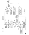
- Fig. 3 is a flow chart illustrative of an air control method embodying the invention; and
- Fig. 4 is a graphic representation showing the relation between ambient temperature and output of a drive unit.
- Referring to Fig. 1, a
throttle valve body 10 has an interiorair intake conduit 12 in which athrottle valve 14 is rotatably mounted. Fixed to thethrottle valve 14 is athrottle valve lever 16 which is actuated by adrive unit 18 to rotate thethrottle valve 14 so that thethrottle valve 14 is opened or closed to control the amount of air being supplied to an internal combustion engine. - For illustration purpose only, the
drive unit 18 takes the form of a DC motor but it may be in the form of a proportional solenoid, a pneumatic motor or the like. - Coupled to the
throttle valve 14 is anangle sensor 20, for example, in the form of a potentiometer adapted to detect an open angle of thethrottle valve 14 which is measured with respect to a reference angular position. - Signals from the
angle sensor 20 are applied to a stored program typedigital computer 22 which is constituted by, for example, a microcomputer and hereinafter referred to as a controller. - Also applied to the
controller 22 are signals from a temperature sensor 24 adapted to detect temperatures T of cooling water for the internal combustion engine and signals from arevolution sensor 26 adapted to detect rotation speeds of the internal combustion engine. - Built in the
controller 22 is a memory in the form of a read only memory, for example, in which a binary data of a control characteristic as shown in Fig. 2 is stored. The characteristic of Fig. 2 is illustrative ofcontrol signals 8 applied to thedrive unit 18 corresponding to temperatures of cooling water, and in this embodiment, the control signal is converted into a corresponding number of pulses which are to be applied to the DC motor. A pulse number is representative of an opening of thethrottle valve 14, in other words, an amount of air to be supplied to the internal combustion engine. - In this manner, amounts of air corresponding to cooling water temperatures upon start of the internal combustion engine can be obtained.
- The operation of the apparatus will now be described with reference to a flow chart as shown in Fig. 3.
- In Fig. 3, an ignition switch for starting the internal combustion engine is first turned on. Subsequently, it is detected in
step 28 as to whether or not thethrottle valve 14 is conditioned to have an idle opening. The idle opening is detected by a separate idle switch. If thethrottle valve 14 is not with the idle opening, a control signal for closing thethrottle valve 14 is generated instep 30 so that thethrottle valve 14 may be restored to the idle opening, and a pulse signal based on this control signal is applied to thedrive unit 18 instep 32. - If it is judged in the
step 28 that thethrottle valve 14 is conditioned to have the idle opening, a temperature of cooling water is detected in step 34 and acontrol signal 8 corresponding to that cooling water temperature is read out of the memory in accordance with the characteristic of Fig. 2 instep 36 to thereby determine a pulse number corresponding to the control signal. - Subsequently, in the
step 32, pulses are applied to thedrive unit 18 so that an opening of thethrottle valve 14 may be set on the basis of this pulse number. After completion of the application of the pulses, a starter switch is turned on to start the internal combustion engine. - Consequently, upon engine start, the
throttle valve 14 is conditioned to have the opening in accordance with the engine temperature and therefore excellent start of the internal combustion engine can be accomplished. - Through the
steps throttle valve 14 can basically be determined but a problem may arise as described below. - More particularly, the
drive unit 18 is a mechanical component and when considering a DC motor standing for thedrive unit 18, the stroke of the shaft of DC motor (movement of the shaft for moving the throttle valve lever 16) is affected by viscosity of lubricating oil applied to a speed reduction gear train and the shaft and it will therefore vary even when the same number of pulses is applied to the DC motor. - Fig. 4 shows how the stroke varies for the same number of pulses with parameters of ambient temperatures of -20°C and +20°C, exhibiting that the lower the temperature, the smaller the stroke becomes.
- Accordingly, the flow procedure through the
steps drive unit 18 dependent on the ambient temperatures can not be corrected. - To obviate the above problem, a countermeasure to be described below is effective.
- Turning to Fig. 3, a temperature Tw of cooling water is detected in
step 38 and acontrol signal 8 corresponding to this temperature is read out of the memory in accordance with the characteristic of Fig. 2 instep 40. - The control signal 6 has a predetermined width as shown at dotted lines in Fig. 2, in other words, a blind zone defined by an upper limit θh and a lower limit θℓ. This blind zone is effective to prevent hunting.
- Subsequently, an opening 8th of the
throttle valve 14 under this condition is detected instep 42 by using theangle sensor 20. The detected opening 8th is compared with the upper limit eh of the control signal instep 44. If it is judged from the comparison that the actual opening θth of the throttle valve is larger than the upper limit θh of the control signal, correction pulses for closing thethrottle valve 14 are generated instep 46 on the basis of 8h - 8th and applied to thedrive unit 18 in thestep 32. - If, on the other hand, it is judged in the
step 44 that the actual throttle valve opening 8th is smaller than the upper limit θh of the control signal, this actual opening 8th is compared with the lower limit θℓ instep 48. - If it is judged in the
step 48 that the actual opening 8th is smaller than the lower limit θℓ, correction pulses for opening thethrottle valve 14 are generated instep 50 on the basis of θℓ - θth and applied to thedrive unit 18 in thestep 32. - If, on the other hand, it is judged in the
step 48 that the actual throttle valve opening θth is larger than the lower limit θℓ of the control signal, indicating that this actual opening θth falls within the blind zone defined by the upper and lower limits θh and θℓ, pulses corresponding to thecontrol signal 8 are generated instep 52 and applied to thedrive unit 18 in thestep 32. - After completion of this flow procedure, the starter switch is turned on to start the internal combustion engine.
- In this manner, an accurate opening of the throttle valve corresponding to the control signal 6 can be obtained.
- While in the foregoing embodiment the throttle valve is used by itself for air amount controlling, an air amount control valve may alternatively be provided in a conduit which by-passes the throttle valve and the opening of the air amount control valve may be controlled.
Claims (11)
Applications Claiming Priority (2)
| Application Number | Priority Date | Filing Date | Title |
|---|---|---|---|
| JP128953/82 | 1982-07-26 | ||
| JP57128953A JPS5920539A (en) | 1982-07-26 | 1982-07-26 | Internal combustion engine throttle valve control device |
Publications (3)
| Publication Number | Publication Date |
|---|---|
| EP0100063A2 true EP0100063A2 (en) | 1984-02-08 |
| EP0100063A3 EP0100063A3 (en) | 1984-08-22 |
| EP0100063B1 EP0100063B1 (en) | 1987-07-15 |
Family
ID=14997487
Family Applications (1)
| Application Number | Title | Priority Date | Filing Date |
|---|---|---|---|
| EP83107109A Expired EP0100063B1 (en) | 1982-07-26 | 1983-07-20 | Apparatus and method for controlling air amount upon engine start |
Country Status (4)
| Country | Link |
|---|---|
| US (1) | US4523561A (en) |
| EP (1) | EP0100063B1 (en) |
| JP (1) | JPS5920539A (en) |
| DE (1) | DE3372520D1 (en) |
Cited By (2)
| Publication number | Priority date | Publication date | Assignee | Title |
|---|---|---|---|---|
| EP0249340A3 (en) * | 1986-05-12 | 1988-11-30 | Mitsubishi Denki Kabushiki Kaisha | Device for controlling the idling operation of an internal combustion engine |
| EP3144072A1 (en) | 2015-09-17 | 2017-03-22 | Henkel AG & Co. KGaA | Dispenser, kit and method for applying an activator for a curable cyanoacrylate-based component |
Families Citing this family (11)
| Publication number | Priority date | Publication date | Assignee | Title |
|---|---|---|---|---|
| KR930006052B1 (en) * | 1984-03-15 | 1993-07-03 | 미쯔비시 지도샤 고교 가부시끼가이샤 | Engine control device and control method |
| US4592322A (en) * | 1984-05-30 | 1986-06-03 | Nissan Motor Company, Limited | Apparatus for throttle valve control |
| JPH0631563B2 (en) * | 1984-11-28 | 1994-04-27 | 日本電装株式会社 | Slot valve opening detector |
| JPH076423B2 (en) * | 1985-06-10 | 1995-01-30 | 日産自動車株式会社 | Solenoid valve control device for internal combustion engine |
| US4854283A (en) * | 1986-11-28 | 1989-08-08 | Nippondenso Co., Ltd. | Throttle valve control apparatus |
| DE4036376A1 (en) * | 1990-11-15 | 1992-05-21 | Kloeckner Humboldt Deutz Ag | Temp.-dependent starting control for fuel pump of diesel engine - has temp. switch to control coil excitation and operate injection pump |
| JP3000804B2 (en) * | 1992-10-21 | 2000-01-17 | 日産自動車株式会社 | Hybrid electric vehicle |
| JP3166546B2 (en) * | 1994-08-17 | 2001-05-14 | トヨタ自動車株式会社 | Internal combustion engine |
| US6668530B2 (en) | 2002-03-13 | 2003-12-30 | Generac Power Systems, Inc. | Grass-cutting tractor with improved operating features |
| US6752110B2 (en) * | 2002-09-20 | 2004-06-22 | Briggs & Stratton Corporation | Electromechanical choke system for an internal combustion engine |
| AU2015252884A1 (en) | 2014-05-01 | 2016-11-17 | Briggs & Stratton Corporation | Electronic governor system and load sensing system |
Family Cites Families (15)
| Publication number | Priority date | Publication date | Assignee | Title |
|---|---|---|---|---|
| US3964457A (en) * | 1974-06-14 | 1976-06-22 | The Bendix Corporation | Closed loop fast idle control system |
| JPS5578138A (en) * | 1978-12-06 | 1980-06-12 | Nissan Motor Co Ltd | Idling speed control for internal combustion engine |
| US4237833A (en) * | 1979-04-16 | 1980-12-09 | General Motors Corporation | Vehicle throttle stop control apparatus |
| JPS55160135A (en) * | 1979-05-29 | 1980-12-12 | Nissan Motor Co Ltd | Suction air controller |
| JPS5644431A (en) * | 1979-09-14 | 1981-04-23 | Nippon Denso Co Ltd | Method of controlling revolution speed of engine |
| JPS6038544B2 (en) * | 1979-10-17 | 1985-09-02 | 株式会社デンソー | Engine speed control method |
| US4383506A (en) * | 1979-12-28 | 1983-05-17 | Hitachi, Ltd. | Engine rotation speed control system |
| JPS56118529A (en) * | 1980-02-22 | 1981-09-17 | Nippon Denso Co Ltd | Rotational speed controlling method for engine |
| JPS56126633A (en) * | 1980-03-07 | 1981-10-03 | Fuji Heavy Ind Ltd | Automatic speed governor for engine |
| JPS56135730A (en) * | 1980-03-27 | 1981-10-23 | Nissan Motor Co Ltd | Controlling device for rotational number of internal combustion engine |
| JPS5718436A (en) * | 1980-07-07 | 1982-01-30 | Toyota Motor Corp | Method of controlling idling revolving rate |
| US4363303A (en) * | 1980-09-03 | 1982-12-14 | Hitachi, Ltd. | Throttle valve opening control device |
| IT1134984B (en) * | 1981-01-09 | 1986-08-20 | Alfa Romeo Spa | DEVICE FOR AUTOMATIC ADJUSTMENT OF THE ROTATION SPEED OF A COMBUSTION ENGINE WORKING AT MINIMUM EMPTY |
| JPS57119135A (en) * | 1981-01-19 | 1982-07-24 | Toyota Motor Corp | Method of controlling idling revolution speed of internal combustion engine |
| DE3142360A1 (en) * | 1981-10-26 | 1983-05-05 | Bosch und Pierburg System oHG, 4040 Neuss | METHOD AND DEVICE FOR REGULATING THE SPEED OF AN INTERNAL COMBUSTION ENGINE |
-
1982
- 1982-07-26 JP JP57128953A patent/JPS5920539A/en active Pending
-
1983
- 1983-07-20 DE DE8383107109T patent/DE3372520D1/en not_active Expired
- 1983-07-20 EP EP83107109A patent/EP0100063B1/en not_active Expired
- 1983-07-21 US US06/515,967 patent/US4523561A/en not_active Expired - Fee Related
Cited By (2)
| Publication number | Priority date | Publication date | Assignee | Title |
|---|---|---|---|---|
| EP0249340A3 (en) * | 1986-05-12 | 1988-11-30 | Mitsubishi Denki Kabushiki Kaisha | Device for controlling the idling operation of an internal combustion engine |
| EP3144072A1 (en) | 2015-09-17 | 2017-03-22 | Henkel AG & Co. KGaA | Dispenser, kit and method for applying an activator for a curable cyanoacrylate-based component |
Also Published As
| Publication number | Publication date |
|---|---|
| EP0100063B1 (en) | 1987-07-15 |
| DE3372520D1 (en) | 1987-08-20 |
| EP0100063A3 (en) | 1984-08-22 |
| JPS5920539A (en) | 1984-02-02 |
| US4523561A (en) | 1985-06-18 |
Similar Documents
| Publication | Publication Date | Title |
|---|---|---|
| US5107246A (en) | Apparatus and method for determining a failure of a temperature sensor for an automatic transmission | |
| US4523561A (en) | Apparatus and method for controlling air amount upon engine start | |
| US5235527A (en) | Method for diagnosing abnormality of sensor | |
| US4581924A (en) | Method of detecting opening of a throttle valve in a fully closed position in an internal combustion engine | |
| US4347570A (en) | Method and apparatus for controlling ignition coil energization | |
| US4385602A (en) | Rotational speed control device during idling of engine | |
| US4515009A (en) | Method for detecting opening of a throttle valve in a fully closed position in an internal combustion engine | |
| SE458290B (en) | DEVICE FOR CONTROL OF CHARGING PRESSURE IN A TURBOLED FORMING ENGINE | |
| JP4074463B2 (en) | Control shaft rotation angle position sensor output reference position learning device in variable valve system of internal combustion engine | |
| US5293852A (en) | Method and arrangement for the open-loop and/or close-loop control of an operating variable of an internal combustion engine | |
| GB2339030A (en) | Engine management system using rotational speed information | |
| US4474151A (en) | Engine revolution speed control device | |
| US4469064A (en) | Apparatus for controlling internal combustion engine | |
| KR0148840B1 (en) | Diagnostic system for idle speed control valve | |
| US4572122A (en) | Method of controlling internal combustion engine | |
| US5692488A (en) | Method for automatic calibration of an angle mark transmitter at the crankshaft of an internal combustion engine | |
| JPH11229943A (en) | Diagnostic device for electronically controlled throttle device | |
| US4785779A (en) | Internal combustion engine control apparatus | |
| US4440128A (en) | Method and apparatus for controlling the idling rotational speed of an internal combustion engine | |
| US5345920A (en) | Supercharging pressure control system for supercharged internal combustion engines | |
| US4523138A (en) | Drive control method for stepping motors | |
| US5584272A (en) | Method and arrangement for controlling an adjusting device for vehicles | |
| US7730860B2 (en) | Actuator control apparatus and method | |
| JPS6146409A (en) | Lubricant supplying device of engine | |
| JP2696441B2 (en) | Idle position detection device for internal combustion engine |
Legal Events
| Date | Code | Title | Description |
|---|---|---|---|
| PUAI | Public reference made under article 153(3) epc to a published international application that has entered the european phase |
Free format text: ORIGINAL CODE: 0009012 |
|
| AK | Designated contracting states |
Designated state(s): DE FR GB IT SE |
|
| PUAL | Search report despatched |
Free format text: ORIGINAL CODE: 0009013 |
|
| AK | Designated contracting states |
Designated state(s): DE FR GB IT SE |
|
| 17P | Request for examination filed |
Effective date: 19840828 |
|
| GRAA | (expected) grant |
Free format text: ORIGINAL CODE: 0009210 |
|
| AK | Designated contracting states |
Kind code of ref document: B1 Designated state(s): DE FR GB |
|
| REF | Corresponds to: |
Ref document number: 3372520 Country of ref document: DE Date of ref document: 19870820 |
|
| ET | Fr: translation filed | ||
| PLBE | No opposition filed within time limit |
Free format text: ORIGINAL CODE: 0009261 |
|
| STAA | Information on the status of an ep patent application or granted ep patent |
Free format text: STATUS: NO OPPOSITION FILED WITHIN TIME LIMIT |
|
| 26N | No opposition filed | ||
| PGFP | Annual fee paid to national office [announced via postgrant information from national office to epo] |
Ref country code: FR Payment date: 19890609 Year of fee payment: 7 |
|
| PG25 | Lapsed in a contracting state [announced via postgrant information from national office to epo] |
Ref country code: FR Effective date: 19910329 |
|
| REG | Reference to a national code |
Ref country code: FR Ref legal event code: ST |
|
| PGFP | Annual fee paid to national office [announced via postgrant information from national office to epo] |
Ref country code: GB Payment date: 19910710 Year of fee payment: 9 |
|
| PGFP | Annual fee paid to national office [announced via postgrant information from national office to epo] |
Ref country code: DE Payment date: 19910827 Year of fee payment: 9 |
|
| PG25 | Lapsed in a contracting state [announced via postgrant information from national office to epo] |
Ref country code: GB Effective date: 19920720 |
|
| GBPC | Gb: european patent ceased through non-payment of renewal fee |
Effective date: 19920720 |
|
| PG25 | Lapsed in a contracting state [announced via postgrant information from national office to epo] |
Ref country code: DE Effective date: 19930401 |