EP0099836B1 - Low bulk seam for papermakers equipment fabrics and method of producing said seam - Google Patents
Low bulk seam for papermakers equipment fabrics and method of producing said seam Download PDFInfo
- Publication number
- EP0099836B1 EP0099836B1 EP19830401494 EP83401494A EP0099836B1 EP 0099836 B1 EP0099836 B1 EP 0099836B1 EP 19830401494 EP19830401494 EP 19830401494 EP 83401494 A EP83401494 A EP 83401494A EP 0099836 B1 EP0099836 B1 EP 0099836B1
- Authority
- EP
- European Patent Office
- Prior art keywords
- fabric
- yarns
- overlap portion
- loops
- fold line
- Prior art date
- Legal status (The legal status is an assumption and is not a legal conclusion. Google has not performed a legal analysis and makes no representation as to the accuracy of the status listed.)
- Expired
Links
Images


Classifications
-
- D—TEXTILES; PAPER
- D21—PAPER-MAKING; PRODUCTION OF CELLULOSE
- D21F—PAPER-MAKING MACHINES; METHODS OF PRODUCING PAPER THEREON
- D21F1/00—Wet end of machines for making continuous webs of paper
- D21F1/0027—Screen-cloths
- D21F1/0054—Seams thereof
Definitions
- the present invention relates to a papermakers fabric comprising a woven fabric having at least one system of filament yarns extending in the machine direction interwoven with at least one system of filament yarns extending in the cross machine direction, each end of said fabric having an overlap portion folded back upon the fabric body defining a fold line, with an area free of cross machine direction yarns adjacent the fold line and with selected machine direction yarns having segments extending from the fold line and defining a series of loops, each overlap portion being secured to the fabric body by stitchings.
- the series of loops of one end is introduced between the series of loops of the other end to form a channel for receiving a pintle wire or joining wire.
- a papermakers fabric is described in the document DE-A-2 064 085.
- Additional cross machine direction yarns are interwoven with machine direction yarns near the loops. Said additional yarns are stronger and more flexible than the original cross machine direction yarns in order to prevent them from sliding into the loops.
- the papermakers fabric according to the invention not having these drawbacks is characterized in that remaining non-loop forming yarns are pulled from the area away from the loops against the fold line and through the overlap portion.
- the present invention relates also to a method of producing a low bulk pin-type seam in a length of flat woven fabric for use with paper making equipment, said length of flat woven fabric comprising a plurality of continuous filament warp yarns interwoven with a plurality of pick yarns, by removing selected pick yarns from a portion of the fabric to create a pick free area adjacent the end to define a fold line which corresponds to the fabric end of one of the sides of the seam to be formed, the fold line defining adjacent fabric body and fabric overlap portion on the fabric, by folding the overlap portion at the fold line to overlap the fabric body to form a series of loops, and by securing the overlap portion to the fabric body by stitchings, characterized by
- the present invention is directed to a fabric having a low bulk pin-type seam.
- the seam is constructed by forming loops in each end of a flat woven papermakers fabric.
- the loops are formed from machine direction yarns which are selected from a portion of the fabric which had previously been freed of all cross machine direction yarns.
- the fabric is folded back on itself in the manner of a hem and selected machine direction yarns are pulled through the fabric to bind the fabric body and fold over together. Both ends of the fabric are made similar and when mated together, the loops forming yarns define a channel which receives the pin or pintle wire.
- Fig. 1 there is shown a fragmentary view of one end of the fabric 2 which is to be seamed.
- the fabric 2 is woven in the usual manner with a plurality of warp yarns or machine direction yarns interlacing with a plurality of pick or cross machine direction yarns 6 and 8.
- the warp yarns are preferably monofilament or continuous filament yarns, however, they may be spun yarns which are twisted or treated so as to behave as a continuous or monofilament yarns. Additionally, it will be understood that the warp yarns may be of any cross sectional shape, i.e. round, square, oval, rectangular, etc., according to fabric design. Likewise, the pick yarns may be any of the available yarns selected according to fabric design.
- the fragmentary view of the fabric 2 shown in Fig. 1 is a duplex fabric having two pick systems, comprised of yarns 6 in one pick system and yarns 8 in the other pick system, interwoven with a single warp or machine direction system 4.
- the overall length of the fabric prior to seaming is somewhat.longer than the length of the final seamed fabric in order to provide the material necessary for fabric seaming and subsequent treatment. While the fabric 2 may be cut to the predetermined width of the desired fabric, it has been found that it is advantageous to have approximately 50 mm of additional width in the unseamed fabric in order to facilitate the ease of seaming.
- the fabric end is prepared for seaming by removing a plurality of picks 6 and 8 from a predetermined area of the fabric.
- the warp yarns which have been exposed by the removal of the picks are then segregated into loop forming yarns and binder yarns according to a predetermined pattern.
- a loop forming wire is inserted between the warp yarns which will essentially separate the fabric into 2 levels.
- the forming wire is located as close to the body of the fabric is as possible.
- the fabric is then placed on a work table with the fabric faced down.
- the free end of the fabric is then folded back toward the body of the fabric in the manner of a hem. The folding back of the free end of the fabric thus produces a plurality of loops extending from the fabric fold or hem line.
- the binder warp ends noted previously are then drawn back into the folded over section of the fabric. After the binder yarns have been pulled back into the fold over of the fabric, the fold over section of the fabric is cut to width. Stitches are then placed in the seam area to additionally secure the fold over and fabric together. The fold over is then trimmed or cut to length and beveled or rounded as is known in the art.
- Fig. 1 the preparation of one end of the fabric seam will be described in detail. It will be remembered that the other end of the fabric is prepared in a like manner. Selected picks are removed at an area in from the free end of the fabric in order to provide sufficient material for the fold over section. In the preferred embodiment, the pick removal area is approximately 125 mm from the free end of the fabric.
- the picks to be removed generally illustrated as 10 are removed in both the face and back pick layers. Picks 10 are removed from the fabric for approximately (10 mm) starting from the end of the fold area previously described. Thus, picks are removed in the area between approximately 125 to 135 mm from the free end of the fabric, this pick free condition is illustrated in Fig. 2 and generally identified as 12.
- a tool 14 such as a long stem awl or scriber, is used to separate pairs of the warp yarns 4. Alternating pairs of warp yarns 4(a) are raised from the plane of the fabric using the tool 14, likewise, alternating pairs of warp yarns 4(b) are left within the plane of the fabric, as illustrated in Fig. 3.
- the operation of raising the warp yarns 4(a) out of the plane of the fabric is difficult to illustrate, however, this will be known to those skilled in the art. As shown in Fig.
- a suitable needle or insertion tool 16 with a forming wire 18 attached is inserted between the raised warp yarns 4(a) and the remaining warp yarns 4(b).
- the forming wire when inserted will overlie the warp yarns 4(b). This condition is illustrated graphically in Fig. 4.
- the forming wire 18 is positioned as close to the body of the fabric as is reasonably possible. In this position the forming wire 18 will be adjacent the fold line or hem line 19 as will be described hereinafter.
- Warp yarns 4(a) will be binder yarns and warp yarns 4(b) will be loop forming yarns.
- the fabric After the fabric has been so prepared, the fabric is positioned on a work table with the fabric face down. Due to the bulk and weight of the flat woven fabric, it has been found advantageous to secure the fabric to the work table such as by tacking or other securing means. With the fabric so positioned, the free end of the fabric is then folded back over the body of the fabric. Once again, it has been found that securing the free end by tacking or other means is advantageous.
- Fig. 5 there is shown the fabric (without the work table) in the folded or hemmed condition just described.
- the fabric has been shown with only the loop forming warp yarns 4(b) extending from the hem line 19 adjacent the forming wire 18.
- the warp yarns 4(a) are still part of the fabric but they are not part of the loop forming warps shown in Fig. 5.
- warp yarns 4(a) are to become the binding yarns which are tight against the fold or hem line and therefore would not appear in the area of the loops in the final configuration.
- the binder warp yarns 4(a) which are not part of the loop, are pulled through the fabric.
- the warp yarns 4(a) can be pulled through the folded over portion or hem of the fabric.
- the yarns 4(a) are shown as the first yarns in the fabric, however, it will be understood that the yarns 4(a) are spaced across fabric at selected locations. The pulling of the warp yarns 4(a) through the fold of the fabric will serve to remove the excess warp length of yarns 4(a) in the area of the loop formed by the yarns 4(b).
- the binder yarns 4(a) are pulled through the fold over with sufficient force to draw the fold over and body of the fabric into intimate contact. It has been found in constructing the seam that the appearance of a ripple may be noted in the fabric fold over or hem on the back of the seam. This ripple phenomenon has not been found to be detrimental to the seam and in fact, it has been found to be a useful indicator that the warp yarns have been pulled with sufficient force against the fold or hem line. Thus, the ripple may be used as an indicator that the pull through has been done correctly. The ripple is not always visible but can be felt with slight hand pressure or the finger tips.
- the pull through of the binder yarns 4(a) which has just been described should be completed so that the loops 24 of slack warp yarns are spaced approximately 50 mm from the position where the loop yarns 4(b) enter the fold over.
- the loops 24 By so spacing the loops 24, it is then possible to trim the fold over so that it may be trimmed or cut at 28 approximately 25 mm from the point where the loop yarns enter the fold over, see Fig. 7.
- the cut edge 28 of the fold over is preferably beveled, see Fig. 8, to aid in the running of the fabric on the papermaking machine.
- The. fold over and fabric body are stitched together in the area adjacent the loops.
- two rows of stitching 30 and 32 are utilized.
- the first row of stitching 30 is located approximately 5 mm from the point where the loops 4(b) enter the fabric and a second row of stitching 32 is placed approximately 15 mm from the first stitch.
- the forming wire 18 is positioned such that. the warps are paired into alternating loop and binder yarns.
- the forming wire 18 is positioned such that the warp yarns are arranged according to the selected repeat pattern. In this repeat pattern, the warp yarns are arranged as two binder, two loop, three binder and one loop yarn per repeat. This repeat pattern provides approximately 25% more binder yarns per seam with and approximately 25% less loop forming yarns per seam with.
- This alternative arrangement has been found to produce a seam which is fully acceptable with respect to strength and performance and which provides additional spacing between the loop forming yarns. The additional spacing between the loop forming yarns has found to be of some benefit in manipulating and aligning the loops in the actual seam formation process.
- repeat pattern selected provide sufficient loop forming yarns to achieve the necessary tensile strength and maintain the seam stability. Likewise, it is required that sufficient binder yarns be provided to maintain the hem tightly and to assure the required tensile strength.
- the fabric weave construction may be according to design selection.
- the other or remaining end of the flat woven belt will be prepared in the manner described above and that after such preparation, the two ends many be mated so that the loops are interleafed and thereby define a channel through which a hinge wire or pintle may be inserted to complete the pin seam.
Landscapes
- Paper (AREA)
Description
- The present invention relates to a papermakers fabric comprising a woven fabric having at least one system of filament yarns extending in the machine direction interwoven with at least one system of filament yarns extending in the cross machine direction, each end of said fabric having an overlap portion folded back upon the fabric body defining a fold line, with an area free of cross machine direction yarns adjacent the fold line and with selected machine direction yarns having segments extending from the fold line and defining a series of loops, each overlap portion being secured to the fabric body by stitchings.
- The series of loops of one end is introduced between the series of loops of the other end to form a channel for receiving a pintle wire or joining wire. Such a papermakers fabric is described in the document DE-A-2 064 085.
- In the known papermakers fabric, machine direction yarns which are not forming loops are cut near the fold line.
- Additional cross machine direction yarns are interwoven with machine direction yarns near the loops. Said additional yarns are stronger and more flexible than the original cross machine direction yarns in order to prevent them from sliding into the loops.
- But there is no real binding of the cross machine direction yarns which can therefore slide into the loops. Further the ends of the cut machine direction yarns can slip out the fabric and mark the paper.
- The papermakers fabric according to the invention not having these drawbacks is characterized in that remaining non-loop forming yarns are pulled from the area away from the loops against the fold line and through the overlap portion.
- The present invention relates also to a method of producing a low bulk pin-type seam in a length of flat woven fabric for use with paper making equipment, said length of flat woven fabric comprising a plurality of continuous filament warp yarns interwoven with a plurality of pick yarns, by removing selected pick yarns from a portion of the fabric to create a pick free area adjacent the end to define a fold line which corresponds to the fabric end of one of the sides of the seam to be formed, the fold line defining adjacent fabric body and fabric overlap portion on the fabric, by folding the overlap portion at the fold line to overlap the fabric body to form a series of loops, and by securing the overlap portion to the fabric body by stitchings, characterized by
- a) prior to folding, raising alternating selected non-loop forming warp yarns in the pick free area from the plane of the fabric, while leaving alternating remaining loop forming warp yarns within the plane of the fabric,
- b) inserting a forming wire between the raised selected warp yarns and the remaining warp yarns such that the forming wire overlies the remaining warp yarns,
- c) folding the overlap portion and the loop forming yarns about the forming wire to form said loops, and
- d) prior to securing the overlap portion to the fabric body, pulling the selected non-loop forming warp yarns from the pick free area away from the loops against the fold line and through the overlap portion.
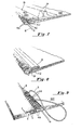
- Fig. 1 is an orthographic projection of a fragment of a fabric end to be seamed in accordance with the invention.
- Fig. 2 is an orthographic projection of the fabric of Fig. 1 with a pick free area.
- Fig. 3 illustrates the separation of warp yarns according to the invention.
- Fig. 4 illustrates the insertion of a loop forming means according to the invention.
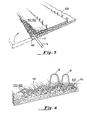
- Fig. 5 illustrates the formation of a fold over or hem according to the invention.
- Fig. 6 illustrates the pull through of selected warp yarns against the hem line according to the invention.
- Fig. 7 illustrates the fabric seam end after pull through of the selected yarns and trimming of the hem.
- Fig. 8 illustrates the fabric of Fig. 7 with beveled edges and stitches according to the invention.
- Fig. 9 illustrates an alternative embodiment according to the invention.
- The present invention is directed to a fabric having a low bulk pin-type seam. The seam is constructed by forming loops in each end of a flat woven papermakers fabric. The loops are formed from machine direction yarns which are selected from a portion of the fabric which had previously been freed of all cross machine direction yarns. The fabric is folded back on itself in the manner of a hem and selected machine direction yarns are pulled through the fabric to bind the fabric body and fold over together. Both ends of the fabric are made similar and when mated together, the loops forming yarns define a channel which receives the pin or pintle wire.
- Although specific forms of the invention have been selected for illustration and the following description will refer in specific terms to those drawings, this description is not intended to limit the scope of the invention which is defined in the claims appended hereto.
- The invention will be set forth with references to the attached drawings, wherein like numerals indicate like elements in all views. The following description is intended to aid in an understanding of the invention and it is understood that the invention may be utilized with weaves or fabrics not specifically described in detail.
- Referring now to Fig. 1, there is shown a fragmentary view of one end of the
fabric 2 which is to be seamed. Thefabric 2 is woven in the usual manner with a plurality of warp yarns or machine direction yarns interlacing with a plurality of pick or crossmachine direction yarns fabric 2 shown in Fig. 1 is a duplex fabric having two pick systems, comprised ofyarns 6 in one pick system andyarns 8 in the other pick system, interwoven with a single warp ormachine direction system 4. As will also be known to those skilled in the art, the overall length of the fabric prior to seaming is somewhat.longer than the length of the final seamed fabric in order to provide the material necessary for fabric seaming and subsequent treatment. While thefabric 2 may be cut to the predetermined width of the desired fabric, it has been found that it is advantageous to have approximately 50 mm of additional width in the unseamed fabric in order to facilitate the ease of seaming. - Generally, the fabric end is prepared for seaming by removing a plurality of
picks - With reference to Fig. 1, the preparation of one end of the fabric seam will be described in detail. It will be remembered that the other end of the fabric is prepared in a like manner. Selected picks are removed at an area in from the free end of the fabric in order to provide sufficient material for the fold over section. In the preferred embodiment, the pick removal area is approximately 125 mm from the free end of the fabric. The picks to be removed, generally illustrated as 10 are removed in both the face and back pick layers.
Picks 10 are removed from the fabric for approximately (10 mm) starting from the end of the fold area previously described. Thus, picks are removed in the area between approximately 125 to 135 mm from the free end of the fabric, this pick free condition is illustrated in Fig. 2 and generally identified as 12. - Referring now to Fig. 3, a
tool 14 such as a long stem awl or scriber, is used to separate pairs of thewarp yarns 4. Alternating pairs of warp yarns 4(a) are raised from the plane of the fabric using thetool 14, likewise, alternating pairs of warp yarns 4(b) are left within the plane of the fabric, as illustrated in Fig. 3. The operation of raising the warp yarns 4(a) out of the plane of the fabric is difficult to illustrate, however, this will be known to those skilled in the art. As shown in Fig. 3, after a number of the warp yarns 4(a) have been raised from the plane of the fabric, a suitable needle orinsertion tool 16 with a formingwire 18 attached is inserted between the raised warp yarns 4(a) and the remaining warp yarns 4(b). Note that since the warp yarns 4(b) have not been disturbed with respect to the plane of the fabric, the forming wire when inserted will overlie the warp yarns 4(b). This condition is illustrated graphically in Fig. 4. The formingwire 18 is positioned as close to the body of the fabric as is reasonably possible. In this position the formingwire 18 will be adjacent the fold line or hemline 19 as will be described hereinafter. Warp yarns 4(a) will be binder yarns and warp yarns 4(b) will be loop forming yarns. - After the fabric has been so prepared, the fabric is positioned on a work table with the fabric face down. Due to the bulk and weight of the flat woven fabric, it has been found advantageous to secure the fabric to the work table such as by tacking or other securing means. With the fabric so positioned, the free end of the fabric is then folded back over the body of the fabric. Once again, it has been found that securing the free end by tacking or other means is advantageous.
- With reference now to Fig. 5, there is shown the fabric (without the work table) in the folded or hemmed condition just described. For purposes of clarity of illustration, the fabric has been shown with only the loop forming warp yarns 4(b) extending from the
hem line 19 adjacent the formingwire 18. It will be understood that the warp yarns 4(a) are still part of the fabric but they are not part of the loop forming warps shown in Fig. 5. Also it should be remembered that warp yarns 4(a) are to become the binding yarns which are tight against the fold or hem line and therefore would not appear in the area of the loops in the final configuration. - After the fabric has been secured to a work surface and has been folded as indicated in Fig. 5, the binder warp yarns 4(a), which are not part of the loop, are pulled through the fabric. With reference to Fig. 6, it can be seen that the warp yarns 4(a) can be pulled through the folded over portion or hem of the fabric. For purpose of clarity, the yarns 4(a) are shown as the first yarns in the fabric, however, it will be understood that the yarns 4(a) are spaced across fabric at selected locations. The pulling of the warp yarns 4(a) through the fold of the fabric will serve to remove the excess warp length of yarns 4(a) in the area of the loop formed by the yarns 4(b). In pulling the warp yarns 4(a) through the fold over or hem it has been found beneficial to tocate the outermost warp yarn and to begin pulling the slack out of the yarn created by the fold over. The pull through then proceeds across the width of the fabric until all of the binding yarns have had the slacks removed therefrom. While it is not necessary, it has on occasion been found beneficial to spray the warp yarns to be pulled through with a silicone lubricant. However, in using a silicone lubricant, care should be exercised because an excess application of silicone lubricant has also been found to create a sticky or tacky surface on the yarns which may actually hinder the pull through. The binder yarns 4(a) are pulled through the fold over with sufficient force to draw the fold over and body of the fabric into intimate contact. It has been found in constructing the seam that the appearance of a ripple may be noted in the fabric fold over or hem on the back of the seam. This ripple phenomenon has not been found to be detrimental to the seam and in fact, it has been found to be a useful indicator that the warp yarns have been pulled with sufficient force against the fold or hem line. Thus, the ripple may be used as an indicator that the pull through has been done correctly. The ripple is not always visible but can be felt with slight hand pressure or the finger tips. The pull through of the binder yarns 4(a) which has just been described should be completed so that the
loops 24 of slack warp yarns are spaced approximately 50 mm from the position where the loop yarns 4(b) enter the fold over. By so spacing theloops 24, it is then possible to trim the fold over so that it may be trimmed or cut at 28 approximately 25 mm from the point where the loop yarns enter the fold over, see Fig. 7. As it will be recognized by those skilled in the art, thecut edge 28 of the fold over is preferably beveled, see Fig. 8, to aid in the running of the fabric on the papermaking machine. - The. fold over and fabric body are stitched together in the area adjacent the loops. With reference to Fig. 8, in the preferred embodiment two rows of stitching 30 and 32 are utilized. The first row of
stitching 30 is located approximately 5 mm from the point where the loops 4(b) enter the fabric and a second row ofstitching 32 is placed approximately 15 mm from the first stitch. In applications where a smooth seam surface is essential, it has been found to be beneficial to remove a face pick in the position where thestitching stitching - With respect to Figure 9, there is illustrated an alternative embodiment which in all respects not set forth hereinafter will be the same as the fabric illustrated in Figure 4. In Figure 4, the forming
wire 18 is positioned such that. the warps are paired into alternating loop and binder yarns. At Figure 9, the formingwire 18 is positioned such that the warp yarns are arranged according to the selected repeat pattern. In this repeat pattern, the warp yarns are arranged as two binder, two loop, three binder and one loop yarn per repeat. This repeat pattern provides approximately 25% more binder yarns per seam with and approximately 25% less loop forming yarns per seam with. This alternative arrangement has been found to produce a seam which is fully acceptable with respect to strength and performance and which provides additional spacing between the loop forming yarns. The additional spacing between the loop forming yarns has found to be of some benefit in manipulating and aligning the loops in the actual seam formation process. - It will be recognized that many various repeat patterns will be possible with the instant invention. The essential feature is that the repeat pattern selected provide sufficient loop forming yarns to achieve the necessary tensile strength and maintain the seam stability. Likewise, it is required that sufficient binder yarns be provided to maintain the hem tightly and to assure the required tensile strength.
- Seams according to the invention have been made in both single ply and multiply fabrics.
- As noted previously, the fabric weave construction may be according to design selection.
- It will be understood that the other or remaining end of the flat woven belt will be prepared in the manner described above and that after such preparation, the two ends many be mated so that the loops are interleafed and thereby define a channel through which a hinge wire or pintle may be inserted to complete the pin seam.
- It will be understood that no back weaving is required to form the loop and that no additional clipper hooks or coils are in the insert seam.
Claims (3)
Applications Claiming Priority (2)
| Application Number | Priority Date | Filing Date | Title |
|---|---|---|---|
| US39999282A | 1982-07-20 | 1982-07-20 | |
| US399992 | 1982-07-20 |
Publications (3)
| Publication Number | Publication Date |
|---|---|
| EP0099836A2 EP0099836A2 (en) | 1984-02-01 |
| EP0099836A3 EP0099836A3 (en) | 1984-03-28 |
| EP0099836B1 true EP0099836B1 (en) | 1987-03-25 |
Family
ID=23581772
Family Applications (1)
| Application Number | Title | Priority Date | Filing Date |
|---|---|---|---|
| EP19830401494 Expired EP0099836B1 (en) | 1982-07-20 | 1983-07-20 | Low bulk seam for papermakers equipment fabrics and method of producing said seam |
Country Status (3)
| Country | Link |
|---|---|
| EP (1) | EP0099836B1 (en) |
| CA (1) | CA1212565A (en) |
| DE (1) | DE3370496D1 (en) |
Families Citing this family (3)
| Publication number | Priority date | Publication date | Assignee | Title |
|---|---|---|---|---|
| DE3507450A1 (en) * | 1985-03-02 | 1986-09-04 | Thomas Josef Heimbach GmbH & Co, 5160 Düren | DEVICE FOR UNRAILING THREADS FROM A TISSUE |
| US20050268980A1 (en) * | 2004-06-04 | 2005-12-08 | Gardner Curtis L | In-line sandwich seams |
| US8640862B2 (en) | 2006-04-10 | 2014-02-04 | Albany International Corp. | Seam-on laminated belt |
Family Cites Families (5)
| Publication number | Priority date | Publication date | Assignee | Title |
|---|---|---|---|---|
| DE1535811C3 (en) * | 1964-03-11 | 1974-10-03 | Fleissner Gmbh, 6073 Egelsbach | Process for the production of a jacket cladding from a screen fabric that is firmly seated on a base |
| DE2064085A1 (en) * | 1970-12-28 | 1972-07-13 | Württembergische Filztuchfabrik D. Geschmay GmbH, 7320 Göppingen | Splicing of fabric ends - particularly multilayer papermaking dryer fabrics |
| AU527809B2 (en) * | 1978-11-30 | 1983-03-24 | Albany International Corp. | Forming fabric seam and method of producing |
| US4418726A (en) * | 1981-01-12 | 1983-12-06 | Albany International Corp. | Double loop seam for corrugator belts |
| GB2102730B (en) * | 1981-07-31 | 1984-10-31 | Albany Int Corp | Improvements relating to pin seams |
-
1982
- 1982-11-30 CA CA000416636A patent/CA1212565A/en not_active Expired
-
1983
- 1983-07-20 EP EP19830401494 patent/EP0099836B1/en not_active Expired
- 1983-07-20 DE DE8383401494T patent/DE3370496D1/en not_active Expired
Also Published As
| Publication number | Publication date |
|---|---|
| CA1212565A (en) | 1986-10-14 |
| EP0099836A2 (en) | 1984-02-01 |
| DE3370496D1 (en) | 1987-04-30 |
| EP0099836A3 (en) | 1984-03-28 |
Similar Documents
| Publication | Publication Date | Title |
|---|---|---|
| US4695498A (en) | Papermakers flat woven fabric | |
| US5746257A (en) | Corrugator belt seam | |
| US4026331A (en) | Jointing of fabric ends to form an endless structure | |
| US2883734A (en) | Paper-maker's wet felt | |
| US4006760A (en) | Fabric connector seam | |
| KR950013197B1 (en) | Machine felt and its manufacturing method | |
| CA1134659A (en) | Forming fabric seam and method of producing | |
| CA1230800A (en) | In-line pintle loop seam | |
| US6000441A (en) | Multi-layered papermaker's seam product with formed loops | |
| JP2003504533A (en) | Weave | |
| US4103717A (en) | Seam webbing | |
| EP1091029A1 (en) | Woven fabric and method for forming articles therefrom | |
| CN104685123B (en) | Method for preparing the seam region of paper machine clothing substrate fabric | |
| MX2007013860A (en) | Multi-axial seamed papermaking fabric and method. | |
| CA1164258A (en) | Stitchless, low bulk, pin-type seam for use in paper making equipment fabrics, such as dryer felts | |
| US4250822A (en) | Low bulk, pin-type seam for use in paper making equipment fabrics, such as dryer felts | |
| CA1212565A (en) | Low bulk seam for monofilament papermakers equipment fabrics | |
| US3335986A (en) | Hand laced seams | |
| US3892262A (en) | Slide-fastener stringer half with woven-in coupling element and method of making same | |
| US5791383A (en) | Woven fabric belt device | |
| JP4166541B2 (en) | Industrial textile joint and method for producing the same | |
| JPH0129276Y2 (en) | ||
| JPH0324639Y2 (en) | ||
| JPS5925917Y2 (en) | Papermaking dryer-felt joint | |
| JPS6028720Y2 (en) | Joint part in paper dryer canvas |
Legal Events
| Date | Code | Title | Description |
|---|---|---|---|
| PUAI | Public reference made under article 153(3) epc to a published international application that has entered the european phase |
Free format text: ORIGINAL CODE: 0009012 |
|
| PUAL | Search report despatched |
Free format text: ORIGINAL CODE: 0009013 |
|
| AK | Designated contracting states |
Designated state(s): BE CH DE FR GB IT LI NL SE |
|
| RHK1 | Main classification (correction) |
Ipc: D03D 3/04 |
|
| AK | Designated contracting states |
Designated state(s): BE CH DE FR GB IT LI NL SE |
|
| 17P | Request for examination filed |
Effective date: 19840910 |
|
| GRAA | (expected) grant |
Free format text: ORIGINAL CODE: 0009210 |
|
| AK | Designated contracting states |
Kind code of ref document: B1 Designated state(s): BE CH DE FR GB IT LI NL SE |
|
| ITF | It: translation for a ep patent filed | ||
| REF | Corresponds to: |
Ref document number: 3370496 Country of ref document: DE Date of ref document: 19870430 |
|
| ET | Fr: translation filed | ||
| PLBI | Opposition filed |
Free format text: ORIGINAL CODE: 0009260 |
|
| 26 | Opposition filed |
Opponent name: FILZTUCHVERWALTUNGS GMBH Effective date: 19871222 |
|
| NLR1 | Nl: opposition has been filed with the epo |
Opponent name: FILZTUCHVERWALTUNGS GMBH |
|
| PLBM | Termination of opposition procedure: date of legal effect published |
Free format text: ORIGINAL CODE: 0009276 |
|
| PLAD | Information related to termination of opposition procedure modified |
Free format text: ORIGINAL CODE: 0009299OPPC |
|
| STAA | Information on the status of an ep patent application or granted ep patent |
Free format text: STATUS: OPPOSITION PROCEDURE CLOSED |
|
| 27C | Opposition proceedings terminated |
Effective date: 19890713 |
|
| R27C | Opposition proceedings terminated (corrected) |
Effective date: 19890713 |
|
| PGFP | Annual fee paid to national office [announced via postgrant information from national office to epo] |
Ref country code: SE Payment date: 19910521 Year of fee payment: 9 |
|
| PGFP | Annual fee paid to national office [announced via postgrant information from national office to epo] |
Ref country code: CH Payment date: 19910523 Year of fee payment: 9 |
|
| PGFP | Annual fee paid to national office [announced via postgrant information from national office to epo] |
Ref country code: GB Payment date: 19910612 Year of fee payment: 9 Ref country code: DE Payment date: 19910612 Year of fee payment: 9 |
|
| ITTA | It: last paid annual fee | ||
| PGFP | Annual fee paid to national office [announced via postgrant information from national office to epo] |
Ref country code: NL Payment date: 19910731 Year of fee payment: 9 |
|
| PG25 | Lapsed in a contracting state [announced via postgrant information from national office to epo] |
Ref country code: GB Effective date: 19920720 |
|
| PG25 | Lapsed in a contracting state [announced via postgrant information from national office to epo] |
Ref country code: SE Effective date: 19920721 |
|
| PG25 | Lapsed in a contracting state [announced via postgrant information from national office to epo] |
Ref country code: LI Effective date: 19920731 Ref country code: CH Effective date: 19920731 |
|
| PG25 | Lapsed in a contracting state [announced via postgrant information from national office to epo] |
Ref country code: NL Effective date: 19930201 |
|
| NLV4 | Nl: lapsed or anulled due to non-payment of the annual fee | ||
| GBPC | Gb: european patent ceased through non-payment of renewal fee |
Effective date: 19920720 |
|
| REG | Reference to a national code |
Ref country code: CH Ref legal event code: PL |
|
| PG25 | Lapsed in a contracting state [announced via postgrant information from national office to epo] |
Ref country code: DE Effective date: 19930401 |
|
| PGFP | Annual fee paid to national office [announced via postgrant information from national office to epo] |
Ref country code: FR Payment date: 19930527 Year of fee payment: 11 |
|
| PGFP | Annual fee paid to national office [announced via postgrant information from national office to epo] |
Ref country code: BE Payment date: 19930616 Year of fee payment: 11 |
|
| PG25 | Lapsed in a contracting state [announced via postgrant information from national office to epo] |
Ref country code: BE Effective date: 19940731 |
|
| BERE | Be: lapsed |
Owner name: ASTEN GROUP INC. Effective date: 19940731 |
|
| EUG | Se: european patent has lapsed |
Ref document number: 83401494.6 Effective date: 19930204 |
|
| PG25 | Lapsed in a contracting state [announced via postgrant information from national office to epo] |
Ref country code: FR Effective date: 19950331 |
|
| REG | Reference to a national code |
Ref country code: FR Ref legal event code: ST |