EP0099223A2 - Electromechanical release mechanism - Google Patents
Electromechanical release mechanism Download PDFInfo
- Publication number
- EP0099223A2 EP0099223A2 EP83303898A EP83303898A EP0099223A2 EP 0099223 A2 EP0099223 A2 EP 0099223A2 EP 83303898 A EP83303898 A EP 83303898A EP 83303898 A EP83303898 A EP 83303898A EP 0099223 A2 EP0099223 A2 EP 0099223A2
- Authority
- EP
- European Patent Office
- Prior art keywords
- door
- latching
- bar
- mechanism according
- electromagnetic means
- Prior art date
- Legal status (The legal status is an assumption and is not a legal conclusion. Google has not performed a legal analysis and makes no representation as to the accuracy of the status listed.)
- Withdrawn
Links
- 230000007246 mechanism Effects 0.000 title claims abstract description 41
- 230000009471 action Effects 0.000 claims abstract description 15
- 238000001514 detection method Methods 0.000 description 3
- 230000008901 benefit Effects 0.000 description 2
- 230000004907 flux Effects 0.000 description 2
- 238000009434 installation Methods 0.000 description 2
- 239000004033 plastic Substances 0.000 description 2
- 229920003023 plastic Polymers 0.000 description 2
- 238000009966 trimming Methods 0.000 description 2
- 230000000994 depressogenic effect Effects 0.000 description 1
- 238000012423 maintenance Methods 0.000 description 1
- 239000002991 molded plastic Substances 0.000 description 1
- 230000004044 response Effects 0.000 description 1
- 239000000779 smoke Substances 0.000 description 1
Images
Classifications
-
- E—FIXED CONSTRUCTIONS
- E05—LOCKS; KEYS; WINDOW OR DOOR FITTINGS; SAFES
- E05C—BOLTS OR FASTENING DEVICES FOR WINGS, SPECIALLY FOR DOORS OR WINDOWS
- E05C17/00—Devices for holding wings open; Devices for limiting opening of wings or for holding wings open by a movable member extending between frame and wing; Braking devices, stops or buffers, combined therewith
- E05C17/56—Devices for holding wings open; Devices for limiting opening of wings or for holding wings open by a movable member extending between frame and wing; Braking devices, stops or buffers, combined therewith by magnetic or electromagnetic attraction or operated by electric or electromagnetic means
Definitions
- the present invention relates to an automatic release mechanism including electromagnetic means and adapted to hold a door or like member in a first position against the action of a force tending to move that member to a second position, when the electromagnetic means are energised, and to release that member for movement to its second position under the action of said force when the electromagnetic means are de-energised (hereinafter called "a mechanism of the kind stated").
- Mechanisms of the kind stated are often provided in conjunction with fire doors eg in hospitals and other buildings so that a door can normally be held open by energisation of the electromagnetic means (against the force of a conventional self-closer), to provide unobstructed access through the respective doorway, but is released to close automatically by de-energisation of the electromagnetic means in response to the detection of a fire.
- Such mechanisms are "fail-safe" in that they require a constant supply of electrical power to keep the door in its open condition and if that power supply should fail for any reason the door will be released to move into its safety condition, ie closed.
- the devices hitherto available to provide this function do, however, have certain drawbacks.
- the conventional release mechanism comprises an electromagnet fixed in position adjacent to the door and arranged to cooperate with an armature plate mounted on the door, ie so that the electromagnet holds open the door by direct magnetic attraction.
- the electromagnet must develop a constant attractive force on the door such as to exceed the force applied by the self-closer and hence these known devices tend to consume undesirably large amounts of power and are generally required to be mains-powered.
- Another consequence of the high-power operation of known devices is that the magnet tends to become very hot after a continuous period of use and therefore often has to be located adjacent to the top edge of the door to avoid being inadvertently touched. Generally speaking, however, this is not a desirable location from the point of view of wiring-in the device and for maintenance and testing purposes. The excessive heat generated by the device may also itself create a fire hazard.
- release mechanisms according to the invention may also find application in the control of ordinary (non fire-protection) doors or other like members for different purposes. Also, while described herein in relation to a door which is normally held open by the mechanism and released to close when the electromagnetic means are de-energised, mechanisms according to the invention may equally find application in relation to movable members - such as smoke ventilators - which are normally held closed against the action of a self-opening device and are released to open upon de-energisation of the electromagnetic means.
- the invention accordingly resides in a mechanism of the kind stated comprising a latching member associated with the electromagnetic means and arranged normally to be held in a latching position by said electromagnetic means when the latter are energised and to be released into an unlatching position when the electromagnetic means are de-energised; and an engaging member biased to adopt a predetermined position in which it is engageable with a portion of the latching member to hold the door or like member in its said first position against the action of said force when the latching member is in its said latching position;.the engaging member being arranged to move away from its said predetermined position against said bias under the action of said force when the latching member moves to its unlatching position, thereby to disengage from the latching member and release the door or like member for movement to its second said position.
- the latching member comprises a pivotally-mounted bar providing a surface against which the engaging member abuts to hold the door or like member in its first position and which is tilted relative to the engaging member when the bar pivots to its unlatching position so that, in use, the engaging member moves against said surface away from its predetermined position under the action of said force.
- the engaging member may itself comprise a roller carried between a pair of arms or by other cantilever means pivoted to a mounting member for attachment to the door or like member, with spring means biasing the cantilever means to place the roller in said predetermined position;
- the closing or equivalent force on the door or like member is resisted through the latching member which in turn is held in its latching position by the electromagnetic means;
- the mechanical advantage of the latching member can readily be chosen such as to require only a modest magnetic holding force to keep that member in its latching position, and hence the electromagnetic means can be operated at significantly reduced power levels as compared with the conventional form of device described above.
- mechanisms according to the invention may be set up with either the engaging member or the latching member mounted to the door or the like, while the other of those members is fixed eg to an adjacent wall or other structure so as to achieve the specified engagement between the members when the door or the like is in its said first position.
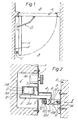
- FIG. 1 there is shown a hinged fire door A in a corridor B.
- This door is normally latched in an open position, as shown in full line, by a mechanism C, so as to provide unrestricted passage through the corridor.
- the door In the event of a fire, however, the door must close automatically to its broken line position shown in Figure 1.
- the door is equipped with a conventional self-closer D which applies a continuous closing force to the door in opposition to the mechanism C.
- the mechanism C includes an electromagnet which, while energised, holds the mechanism in a latching-condition to keep the door open against the force of the self-closer.
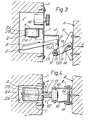
- FIG. 2-4 there is shown one example of a mechanism according to the invention for use as the mechanism C.
- a mounting plate 1 is fixed over a recess E provided in the wall F adjacent to the edge of the door A (when open) at any suitable height, eg at skirting level.
- An electromagnet 2 is mounted within the recess by means of a bracket 3 attached to the plate 1.
- the plate 1 supports a bracket 4 to which an L-shaped latch bar 5 is pivoted by a horizontal pin 6.
- the bar 5 extends through a slot 7 in the mounting plate 1 and at its inner end carries an armature plate 8 for cooperation with the core 2A of the electromagnet 2 and with the inner limb 3A of the bracket 3 (which provides a return path for magnetic flux when the electromagnet is energised). With energising current supplied to the coil 2B of the electromagnet the plate 8 is normally held by the magnet to maintain the latch bar 5 in the generally horizontal orientation illustrated in Figure 2.
- a channel-shaped bracket 9 to which a pair of parallel arms 10 are pivoted by a horizontal pin 11.
- a roller 12 on a pin 13 is carried between the distal ends of the arms 10, and a torsion spring 14 biases the arms to adopt the generally horizontal orientation illustrated in Figure 2.
- the roller 12 engages behind the nose 15 of the latch bar 5 to hold the door A in its open position, against the force of the self-closer acting in the sense of arrow X. More particularly, the roller 12 engages the flat face 15A of the latch bar, which extends substantially perpendicularly to the direction of "pull" on the door, at a point spaced slightly below the pivot pin 6. There is thus applied to the bar 5 a moment tending to pivot the latter in the anticlockwise sense about pin 6 (as viewed in the Figure). Iiowever, this moment is counteracted by the clockwise moment on the bar due to the attractive force of the electromagnet 2 acting on the armature plate 8.
- the moment arm of this magnetic force is many times the moment arm of the closing force acting through the roller 12 so that the force of attraction which the magnet 2 has to develop to hold the door open is only a fraction of the applied closing force.
- the corresponding power consumption of the electromagnet is therefore much lower than that which would be required to hold open the door by direct attraction of an armature plate fixed to the door.
- the magnet may thus be powered eg from a 24V d.c. supply such as is typically used to operate the detection and control equipment of an associated fire alarm system.
- the arms 10 can be depressed manually to clear the bottom of the nose 15 and disengage from the latch bar without disturbing the latter.
- the attraction of the magnet 2 for the plate 8 can be overcome, allowing the latch bar to be moved to "its releasing position of Figure 3;
- reference numeral 16 indicates a "trimming" potentiometer in series with the magnet coil 2B by which the current through the coil and hence the intensity of the attractive force can be adjusted to determine the amount of "pull" required to override the mechanism in this way.
- the mechanism can be set or reset into its latched condition from the door-closed condition either by placing the components by hand into their Figure 2 positions or simply by opening the door and pressing the roller 12 against the latch bar nose 15 - this causes the roller to roll down the arcuate surface 15B of the latch bar.and then spring up behind the surface 15A, the same action serving to pivot the latch bar into its latching position if not already in that position.
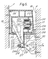
- FIG. 5 shows another automatic release mechanism functionally equivalent to the mechanism of Figures 2-4.
- the latch bar 21 is pivoted on a pin 23 and has a nose portion 24 extending out through a slot 25 at the lower end of the housing 22.
- the bar 21 carries an armature disc 26 for cooperation with the magnet 20, of which the core is indicated at 20A and the energising coil at 20B.
- the outer skirt portion 20C of the core 20A provides a return path for magnetic flux when energised. With energising current supplied to the coil 20B the armature disc 26 is normally held by the magnet to maintain the latch bar in the generally vertical orientation illustration in full line in Figure 5.
- a spring-biased roller 27 mounted to the door A.
- the roller is carried on stubs 28 at the ends of a pair of moulded plastics arms 29 which straddle a mounting body 30 and are pivoted thereto at 31.
- the arms 29 are biased to adopt the generally horizontal orientation illustrated in Figure 5 by means of leaf springs 32 moulded on to the arms engaging stops 33 on the body 30.
- the roller 27 engages the face 24A of the latch bar nose to hold the door open, against the force of the self-closer acting in the sense of arrow X, as in the case of the Figures 2-4 embodiment.
- the latch bar is allowed to pivot to the broken line position of Figure 5 to tilt the face 24A relative to the roller 27.
- the roller accordingly rolls down the face 24A to the position indicated in broken line and disengages from the latch bar to permit closure of the door, again as in the case of the Figures 2-4 embodiment.
- the mechanism can be manually disengaged, and re-set, as described above for the previous'embodiment.
- a "trimming" potentiometer and the terminal connections for the power supply to the magnet 20 are located in a compartment 34 in the casing part 18.
- the latch bar and magnet housing 22 is mounted in the cylindrical "well" 17A of the casing part 17 in this embodiment through a circumferential series of intermeshing splines or teeth 35, which enable the housing 22 to be mounted in any one of a number of selected azimuthal orientations relative to the casing 17 and wall F.
- This is of advantage in aligning the latch bar 21 with the roller 27 in installations where the open door is inclined to the mounting surface for the latch unit (ie, in the case of Figure 1, if the door A opened at an angle to the wall surface F).
- Reference numeral 36 indicates a buffer pad carried by the body 30 to cushion any impact of the door against the latch unit.
Landscapes
- Physics & Mathematics (AREA)
- Electromagnetism (AREA)
- Engineering & Computer Science (AREA)
- Mechanical Engineering (AREA)
- Special Wing (AREA)
Abstract
Description
- The present invention relates to an automatic release mechanism including electromagnetic means and adapted to hold a door or like member in a first position against the action of a force tending to move that member to a second position, when the electromagnetic means are energised, and to release that member for movement to its second position under the action of said force when the electromagnetic means are de-energised (hereinafter called "a mechanism of the kind stated").
- Mechanisms of the kind stated are often provided in conjunction with fire doors eg in hospitals and other buildings so that a door can normally be held open by energisation of the electromagnetic means (against the force of a conventional self-closer), to provide unobstructed access through the respective doorway, but is released to close automatically by de-energisation of the electromagnetic means in response to the detection of a fire. Such mechanisms are "fail-safe" in that they require a constant supply of electrical power to keep the door in its open condition and if that power supply should fail for any reason the door will be released to move into its safety condition, ie closed. The devices hitherto available to provide this function do, however, have certain drawbacks. The conventional release mechanism comprises an electromagnet fixed in position adjacent to the door and arranged to cooperate with an armature plate mounted on the door, ie so that the electromagnet holds open the door by direct magnetic attraction. The electromagnet must develop a constant attractive force on the door such as to exceed the force applied by the self-closer and hence these known devices tend to consume undesirably large amounts of power and are generally required to be mains-powered. Another consequence of the high-power operation of known devices is that the magnet tends to become very hot after a continuous period of use and therefore often has to be located adjacent to the top edge of the door to avoid being inadvertently touched. Generally speaking, however, this is not a desirable location from the point of view of wiring-in the device and for maintenance and testing purposes. The excessive heat generated by the device may also itself create a fire hazard.
- It is therefore an aim of the invention to provide a simple, compact, automatic release mechanism suitable for the service described above but which is capable of operating at lower power levels than the known electromagnetic types. Although primarily intended for use in connection with hinged or sliding fire doors, release mechanisms according to the invention may also find application in the control of ordinary (non fire-protection) doors or other like members for different purposes. Also, while described herein in relation to a door which is normally held open by the mechanism and released to close when the electromagnetic means are de-energised, mechanisms according to the invention may equally find application in relation to movable members - such as smoke ventilators - which are normally held closed against the action of a self-opening device and are released to open upon de-energisation of the electromagnetic means.
- The invention accordingly resides in a mechanism of the kind stated comprising a latching member associated with the electromagnetic means and arranged normally to be held in a latching position by said electromagnetic means when the latter are energised and to be released into an unlatching position when the electromagnetic means are de-energised; and an engaging member biased to adopt a predetermined position in which it is engageable with a portion of the latching member to hold the door or like member in its said first position against the action of said force when the latching member is in its said latching position;.the engaging member being arranged to move away from its said predetermined position against said bias under the action of said force when the latching member moves to its unlatching position, thereby to disengage from the latching member and release the door or like member for movement to its second said position.
- Preferably, the latching member comprises a pivotally-mounted bar providing a surface against which the engaging member abuts to hold the door or like member in its first position and which is tilted relative to the engaging member when the bar pivots to its unlatching position so that, in use, the engaging member moves against said surface away from its predetermined position under the action of said force. The engaging member may itself comprise a roller carried between a pair of arms or by other cantilever means pivoted to a mounting member for attachment to the door or like member, with spring means biasing the cantilever means to place the roller in said predetermined position;
- In a mechanism according to the invention the closing or equivalent force on the door or like member is resisted through the latching member which in turn is held in its latching position by the electromagnetic means; the mechanical advantage of the latching member can readily be chosen such as to require only a modest magnetic holding force to keep that member in its latching position, and hence the electromagnetic means can be operated at significantly reduced power levels as compared with the conventional form of device described above.
- In use, mechanisms according to the invention may be set up with either the engaging member or the latching member mounted to the door or the like, while the other of those members is fixed eg to an adjacent wall or other structure so as to achieve the specified engagement between the members when the door or the like is in its said first position.
- These and other features of the present invention will now be more particularly described, by way of example, with reference to the accompanying drawings, in which:
- Figure 1 is a schematic plan view of a typical installation of a mechanism according to the invention to hold open a fire door;
- Figure 2 is a side view, partly in section, of a first embodiment of a mechanism according to the invention, in its latched condition;
- Figure 3 is a view similar to Figure 2 of the same mechanism in its releasing condition;
- Figure 4 is an underneath plan view of the mechanism as shown in Figure 3; and
- Figure 5 is a side view, partly in section, of a second embodiment of a mechanism according to the invention, indicating both latched and releasing conditions.
- Referring to Figure 1 there is shown a hinged fire door A in a corridor B. This door is normally latched in an open position, as shown in full line, by a mechanism C, so as to provide unrestricted passage through the corridor. In the event of a fire, however, the door must close automatically to its broken line position shown in Figure 1. To this end the door is equipped with a conventional self-closer D which applies a continuous closing force to the door in opposition to the mechanism C. As more fully described hereafter, the mechanism C includes an electromagnet which, while energised, holds the mechanism in a latching-condition to keep the door open against the force of the self-closer. If fire is detected, however, the energising current to the electromagnet is cut off so that the mechanism releases the door to move to its closed position. The provision of a suitable self-closer D and of a suitable fire detection system for controlling the supply of electrical power to the electromagnet in the mechanism C are matters which will be apparent to those skilled in the art and need not be further described herein.
- In Figures 2-4 there is shown one example of a mechanism according to the invention for use as the mechanism C.
A mounting plate 1 is fixed over a recess E provided in the wall F adjacent to the edge of the door A (when open) at any suitable height, eg at skirting level. An electromagnet 2 is mounted within the recess by means of abracket 3 attached to theplate 1. Externally, theplate 1 supports a bracket 4 to which an L-shaped latch bar 5 is pivoted by ahorizontal pin 6. Thebar 5 extends through aslot 7 in themounting plate 1 and at its inner end carries anarmature plate 8 for cooperation with the core 2A of the electromagnet 2 and with theinner limb 3A of the bracket 3 (which provides a return path for magnetic flux when the electromagnet is energised). With energising current supplied to thecoil 2B of the electromagnet theplate 8 is normally held by the magnet to maintain thelatch bar 5 in the generally horizontal orientation illustrated in Figure 2. - Mounted to the door A is a channel-
shaped bracket 9 to which a pair ofparallel arms 10 are pivoted by ahorizontal pin 11. Aroller 12 on apin 13 is carried between the distal ends of thearms 10, and atorsion spring 14 biases the arms to adopt the generally horizontal orientation illustrated in Figure 2. - With the parts disposed as shown in Figure 2 the
roller 12 engages behind thenose 15 of thelatch bar 5 to hold the door A in its open position, against the force of the self-closer acting in the sense of arrow X. More particularly, theroller 12 engages theflat face 15A of the latch bar, which extends substantially perpendicularly to the direction of "pull" on the door, at a point spaced slightly below thepivot pin 6. There is thus applied to the bar 5 a moment tending to pivot the latter in the anticlockwise sense about pin 6 (as viewed in the Figure). Iiowever, this moment is counteracted by the clockwise moment on the bar due to the attractive force of the electromagnet 2 acting on thearmature plate 8. Furthermore, the moment arm of this magnetic force is many times the moment arm of the closing force acting through theroller 12 so that the force of attraction which the magnet 2 has to develop to hold the door open is only a fraction of the applied closing force. The corresponding power consumption of the electromagnet is therefore much lower than that which would be required to hold open the door by direct attraction of an armature plate fixed to the door. The magnet may thus be powered eg from a 24V d.c. supply such as is typically used to operate the detection and control equipment of an associated fire alarm system. - In the event of a fire, the energising current to the
magnet coil 2B is cut off, allowing thelatch bar 5 to pivot anticlockwise to the position shown in Figure 3. This tilts thenose 15 of the bar so that theface 15A is now inclined to the direction of "pull" X applied to theroller 12. The closing force accordingly now acts to roll theroller 12 down along theface 15A, pivoting thearms 10 against the bias ofspring 14 to the position shown in Figure 3, whereupon the roller disengages from the latch bar and allows the door to close. - If it is required to close the door at any time without de- energising the magnet 2 this can be achieved in either of two ways. Firstly, the
arms 10 can be depressed manually to clear the bottom of thenose 15 and disengage from the latch bar without disturbing the latter. Alternatively, if the door is pulled hard enough in the closing direction the attraction of the magnet 2 for theplate 8 can be overcome, allowing the latch bar to be moved to "its releasing position of Figure 3;reference numeral 16 indicates a "trimming" potentiometer in series with themagnet coil 2B by which the current through the coil and hence the intensity of the attractive force can be adjusted to determine the amount of "pull" required to override the mechanism in this way. Similarly, the mechanism can be set or reset into its latched condition from the door-closed condition either by placing the components by hand into their Figure 2 positions or simply by opening the door and pressing theroller 12 against the latch bar nose 15 - this causes the roller to roll down thearcuate surface 15B of the latch bar.and then spring up behind thesurface 15A, the same action serving to pivot the latch bar into its latching position if not already in that position. - Turning now to Figure 5, this shows another automatic release mechanism functionally equivalent to the mechanism of Figures 2-4. In this case there is a two-
part plastics casing 17/18 surface-mounted to the wall F via abackplate 19. Mounted within ths casing is anelectromagnet 20 and astraight latch bar 21 assembled in aplastics housing 22. Thelatch bar 21 is pivoted on apin 23 and has anose portion 24 extending out through aslot 25 at the lower end of thehousing 22. At its upper end thebar 21 carries anarmature disc 26 for cooperation with themagnet 20, of which the core is indicated at 20A and the energising coil at 20B. The outer skirt portion 20C of thecore 20A provides a return path for magnetic flux when energised. With energising current supplied to thecoil 20B thearmature disc 26 is normally held by the magnet to maintain the latch bar in the generally vertical orientation illustration in full line in Figure 5. - For engaging with the
latch bar 21 there is again a spring-biased roller 27 mounted to the door A. The roller is carried onstubs 28 at the ends of a pair ofmoulded plastics arms 29 which straddle a mountingbody 30 and are pivoted thereto at 31. Thearms 29 are biased to adopt the generally horizontal orientation illustrated in Figure 5 by means ofleaf springs 32 moulded on to thearms engaging stops 33 on thebody 30. - With the parts disposed as shown in full line in Figure 5 the
roller 27 engages theface 24A of the latch bar nose to hold the door open, against the force of the self-closer acting in the sense of arrow X, as in the case of the Figures 2-4 embodiment. When the energising current to themagnet coil 20B is cut off, the latch bar is allowed to pivot to the broken line position of Figure 5 to tilt theface 24A relative to theroller 27. The roller accordingly rolls down theface 24A to the position indicated in broken line and disengages from the latch bar to permit closure of the door, again as in the case of the Figures 2-4 embodiment. Likewise, the mechanism can be manually disengaged, and re-set, as described above for the previous'embodiment. A "trimming" potentiometer and the terminal connections for the power supply to the magnet 20 (not shown) are located in acompartment 34 in thecasing part 18. - The latch bar and
magnet housing 22 is mounted in the cylindrical "well" 17A of thecasing part 17 in this embodiment through a circumferential series of intermeshing splines orteeth 35, which enable thehousing 22 to be mounted in any one of a number of selected azimuthal orientations relative to thecasing 17 and wall F. This is of advantage in aligning thelatch bar 21 with theroller 27 in installations where the open door is inclined to the mounting surface for the latch unit (ie, in the case of Figure 1, if the door A opened at an angle to the wall surface F).Reference numeral 36 indicates a buffer pad carried by thebody 30 to cushion any impact of the door against the latch unit.
Claims (9)
Applications Claiming Priority (4)
| Application Number | Priority Date | Filing Date | Title |
|---|---|---|---|
| GB8219941 | 1982-07-09 | ||
| GB8219941 | 1982-07-09 | ||
| GB8225451 | 1982-09-07 | ||
| GB8225451 | 1982-09-07 |
Publications (2)
| Publication Number | Publication Date |
|---|---|
| EP0099223A2 true EP0099223A2 (en) | 1984-01-25 |
| EP0099223A3 EP0099223A3 (en) | 1985-05-15 |
Family
ID=26283308
Family Applications (1)
| Application Number | Title | Priority Date | Filing Date |
|---|---|---|---|
| EP83303898A Withdrawn EP0099223A3 (en) | 1982-07-09 | 1983-07-05 | Electromechanical release mechanism |
Country Status (3)
| Country | Link |
|---|---|
| EP (1) | EP0099223A3 (en) |
| ES (1) | ES8405874A1 (en) |
| GB (1) | GB2123891B (en) |
Cited By (10)
| Publication number | Priority date | Publication date | Assignee | Title |
|---|---|---|---|---|
| US6167654B1 (en) | 1995-04-13 | 2001-01-02 | Michael Wolf | Device for operating hinged or guided closures |
| GB2359335A (en) * | 2000-02-19 | 2001-08-22 | Lawrence Michael Griffin | Alarm activated doorstop |
| US20110026203A1 (en) * | 2005-12-13 | 2011-02-03 | Chris Ligtenberg | Electronic device and magnetic latching mechanism therefore |
| US20140035302A1 (en) * | 2012-07-31 | 2014-02-06 | Airbus Operations Gmbh | Door latching device and door assembly incorporating same |
| US20160356057A1 (en) * | 2015-06-03 | 2016-12-08 | HTI Technology & Industries, Inc. | Powered latching apparatus |
| CN106369529A (en) * | 2016-11-24 | 2017-02-01 | 广州万构建筑工程设计有限公司 | Automatic illuminating emergency equipment |
| CN106500040A (en) * | 2016-11-24 | 2017-03-15 | 广州万构建筑工程设计有限公司 | A kind of device for emergency lighting |
| CN106524044A (en) * | 2016-11-24 | 2017-03-22 | 广州万构建筑工程设计有限公司 | Emergency lighting device |
| US10717390B2 (en) | 2016-05-18 | 2020-07-21 | Shanghai Yanfeng Jinqiao Automotive Trim Systems Co. Ltd. | Console assembly for vehicle interior |
| US11572723B2 (en) | 2019-02-27 | 2023-02-07 | Shanghai Yanfeng Jinqiao Automotive Triim Systems Co. Ltd. | Vehicle interior component |
Families Citing this family (2)
| Publication number | Priority date | Publication date | Assignee | Title |
|---|---|---|---|---|
| US5738392A (en) * | 1995-10-12 | 1998-04-14 | Sony Corporation | Latch for securing an aircraft video device |
| RU2750794C1 (en) * | 2020-11-24 | 2021-07-02 | Общество с ограниченной ответственностью "Инженерно-технический центр "ПРОМИКС" | Electromechanical lock |
Family Cites Families (1)
| Publication number | Priority date | Publication date | Assignee | Title |
|---|---|---|---|---|
| US3258875A (en) * | 1965-05-27 | 1966-07-05 | Barth Safety Equipment Co Inc | Electromagnetic door holder and releaser |
-
1983
- 1983-07-05 EP EP83303898A patent/EP0099223A3/en not_active Withdrawn
- 1983-07-05 GB GB08318182A patent/GB2123891B/en not_active Expired
- 1983-07-08 ES ES523979A patent/ES8405874A1/en not_active Expired
Cited By (17)
| Publication number | Priority date | Publication date | Assignee | Title |
|---|---|---|---|---|
| US6167654B1 (en) | 1995-04-13 | 2001-01-02 | Michael Wolf | Device for operating hinged or guided closures |
| GB2359335A (en) * | 2000-02-19 | 2001-08-22 | Lawrence Michael Griffin | Alarm activated doorstop |
| GB2359335B (en) * | 2000-02-19 | 2003-12-24 | Lawrence Michael Griffin | A doorstop |
| US20110026203A1 (en) * | 2005-12-13 | 2011-02-03 | Chris Ligtenberg | Electronic device and magnetic latching mechanism therefore |
| US8801054B2 (en) | 2005-12-13 | 2014-08-12 | Apple Inc. | Electronic device and magnetic latching mechanism therefor |
| US20140035302A1 (en) * | 2012-07-31 | 2014-02-06 | Airbus Operations Gmbh | Door latching device and door assembly incorporating same |
| US20160356057A1 (en) * | 2015-06-03 | 2016-12-08 | HTI Technology & Industries, Inc. | Powered latching apparatus |
| US11060322B2 (en) * | 2015-06-03 | 2021-07-13 | Hti Technology And Industries, Inc. | Powered latching apparatus |
| US10717390B2 (en) | 2016-05-18 | 2020-07-21 | Shanghai Yanfeng Jinqiao Automotive Trim Systems Co. Ltd. | Console assembly for vehicle interior |
| US10737628B2 (en) | 2016-05-18 | 2020-08-11 | Shanghai Yanfeng Jinqiao Automotive Trim Systems Co. Ltd. | Console assembly for vehicle interior |
| CN106500040A (en) * | 2016-11-24 | 2017-03-15 | 广州万构建筑工程设计有限公司 | A kind of device for emergency lighting |
| CN106500040B (en) * | 2016-11-24 | 2019-04-30 | 中山市德普电子有限公司 | A kind of device for emergency lighting |
| CN106369529B (en) * | 2016-11-24 | 2019-07-02 | 广州万构建筑工程设计有限公司 | A kind of automatic illuminating emergency set |
| CN106524044B (en) * | 2016-11-24 | 2019-01-18 | 上海森智照明科技有限公司 | A kind of emergency-lighting set |
| CN106524044A (en) * | 2016-11-24 | 2017-03-22 | 广州万构建筑工程设计有限公司 | Emergency lighting device |
| CN106369529A (en) * | 2016-11-24 | 2017-02-01 | 广州万构建筑工程设计有限公司 | Automatic illuminating emergency equipment |
| US11572723B2 (en) | 2019-02-27 | 2023-02-07 | Shanghai Yanfeng Jinqiao Automotive Triim Systems Co. Ltd. | Vehicle interior component |
Also Published As
| Publication number | Publication date |
|---|---|
| ES523979A0 (en) | 1984-06-16 |
| ES8405874A1 (en) | 1984-06-16 |
| GB8318182D0 (en) | 1983-08-03 |
| GB2123891B (en) | 1985-10-02 |
| GB2123891A (en) | 1984-02-08 |
| EP0099223A3 (en) | 1985-05-15 |
Similar Documents
| Publication | Publication Date | Title |
|---|---|---|
| EP0099223A2 (en) | Electromechanical release mechanism | |
| US3777423A (en) | Condition responsive door holder-closer | |
| US5082316A (en) | Release mechanism and method with alarm circuit | |
| US4161804A (en) | Heat-actuated door latch | |
| CN212176889U (en) | Prevent fire door electric door closer | |
| US4401346A (en) | Apparatus for controlling the operation of a door | |
| US5605185A (en) | Fire door system | |
| US11619087B2 (en) | Hold-open arrester arrangement having a hold-open function to hold a door open | |
| US3665996A (en) | Closure operator | |
| CA1039464A (en) | Electrically actuated door holder and release | |
| US4034437A (en) | Pressure-free fail-safe emergency door closer | |
| US6167654B1 (en) | Device for operating hinged or guided closures | |
| US6397530B1 (en) | Sliding service window assembly | |
| CN110512980B (en) | Automatic control device for fireproof door | |
| US3258875A (en) | Electromagnetic door holder and releaser | |
| EP0589822B1 (en) | Device for opening a window or a door, especially of the sliding type | |
| CN211647748U (en) | Automatic control device for fireproof door | |
| US5355741A (en) | Failsafe limit switch with automatic reset for rolling fire door | |
| US5085368A (en) | System for controlling poultry house window closures | |
| US3696374A (en) | Cabinet with jam switch and alarm system | |
| US20030057711A1 (en) | Door or window stop | |
| GB2140863A (en) | Device for controlling the movement of a door | |
| CN110528981B (en) | One-way locking mechanism for door opening and closing device | |
| GB2260793A (en) | Apparatus for braking a member, particularly an opening ventilator flap biased to one of two positions | |
| JP6799959B2 (en) | Emergency closure device |
Legal Events
| Date | Code | Title | Description |
|---|---|---|---|
| PUAI | Public reference made under article 153(3) epc to a published international application that has entered the european phase |
Free format text: ORIGINAL CODE: 0009012 |
|
| AK | Designated contracting states |
Designated state(s): AT BE CH DE FR IT LI LU NL SE |
|
| PUAL | Search report despatched |
Free format text: ORIGINAL CODE: 0009013 |
|
| AK | Designated contracting states |
Designated state(s): AT BE CH DE FR IT LI LU NL SE |
|
| 17P | Request for examination filed |
Effective date: 19851118 |
|
| RAP1 | Party data changed (applicant data changed or rights of an application transferred) |
Owner name: VALLAN, RAE KEITH |
|
| 17Q | First examination report despatched |
Effective date: 19871030 |
|
| STAA | Information on the status of an ep patent application or granted ep patent |
Free format text: STATUS: THE APPLICATION IS DEEMED TO BE WITHDRAWN |
|
| 18D | Application deemed to be withdrawn |
Effective date: 19880201 |
|
| RIN1 | Information on inventor provided before grant (corrected) |
Inventor name: VALLAN, RAE KEITH Inventor name: WONG, DAVID WING KWONG |