EP0098442B1 - A motor-driven subjective phorometer - Google Patents
A motor-driven subjective phorometer Download PDFInfo
- Publication number
- EP0098442B1 EP0098442B1 EP83106014A EP83106014A EP0098442B1 EP 0098442 B1 EP0098442 B1 EP 0098442B1 EP 83106014 A EP83106014 A EP 83106014A EP 83106014 A EP83106014 A EP 83106014A EP 0098442 B1 EP0098442 B1 EP 0098442B1
- Authority
- EP
- European Patent Office
- Prior art keywords
- plate
- spherical
- lens
- toric
- phorometer
- Prior art date
- Legal status (The legal status is an assumption and is not a legal conclusion. Google has not performed a legal analysis and makes no representation as to the accuracy of the status listed.)
- Expired
Links
- 230000033001 locomotion Effects 0.000 claims description 10
- 210000003128 head Anatomy 0.000 description 14
- 230000004438 eyesight Effects 0.000 description 10
- 230000001179 pupillary effect Effects 0.000 description 10
- 239000011521 glass Substances 0.000 description 3
- 230000003287 optical effect Effects 0.000 description 3
- 238000010586 diagram Methods 0.000 description 2
- 230000000630 rising effect Effects 0.000 description 2
- 201000009487 Amblyopia Diseases 0.000 description 1
- 206010020015 Heterophoria Diseases 0.000 description 1
- 206010020675 Hypermetropia Diseases 0.000 description 1
- 230000000712 assembly Effects 0.000 description 1
- 238000000429 assembly Methods 0.000 description 1
- 230000008878 coupling Effects 0.000 description 1
- 238000010168 coupling process Methods 0.000 description 1
- 238000005859 coupling reaction Methods 0.000 description 1
- 230000004305 hyperopia Effects 0.000 description 1
- 201000006318 hyperopia Diseases 0.000 description 1
- 238000005259 measurement Methods 0.000 description 1
- 238000000034 method Methods 0.000 description 1
- 230000017105 transposition Effects 0.000 description 1
Images


Classifications
-
- A—HUMAN NECESSITIES
- A61—MEDICAL OR VETERINARY SCIENCE; HYGIENE
- A61B—DIAGNOSIS; SURGERY; IDENTIFICATION
- A61B3/00—Apparatus for testing the eyes; Instruments for examining the eyes
- A61B3/02—Subjective types, i.e. testing apparatus requiring the active assistance of the patient
- A61B3/028—Subjective types, i.e. testing apparatus requiring the active assistance of the patient for testing visual acuity; for determination of refraction, e.g. phoropters
- A61B3/0285—Phoropters
Definitions
- This invention relates to a motor-driven subjective phorometer.
- a motor-driven subjective phorometer according to the first portion of Claim 1 is disclosed in EP ⁇ A ⁇ 0,045,897.
- This known phorometer employs fine stepping motors driven by control and drive signals electronically generated by a computer system.
- the document does not disclose details on the drive system for moving the lens plates.
- the mounting means for the lens plates are manually driven in this prior art.
- An object of this invention is to provide a motor-driven subjective phorometer in which all the measuring means can be actuated simply by a group of control switches or keys gathered in a central panel, and all the data measured can be displayed digitally in a monitor and printed as required, while data possessed previously or obtained from other instruments such as an objective phorometer and the like can be inputted thereto simply by the group of control switches or keys.
- the subjective phorometer may be a desk- type apparatus in which all the measuring elements are set on the desk plate or desk top and all the procedures for measuring vision data of eyes are carried out by control keys or switches on the desk, and all the data.measured are displayed digitally on a monitor, and printed out as required.
- the elements of the phorometer for measuring vision data of eyes such as right-eye and left-eye heads each consisting of two spherical lens plates, two toric lens plates, and an additional plate, an element for raising and lowering the one eye head, an element for convergence of the left-eye head and the right-eye head, and an element for adjusting pupillary distance, and so on, are conventional, but the means for actuating those elements and for displaying the data measured are different from the conventional arrangements.
- the right-eye head and left-eye head are symmetrical relative to each other, so reference will be made to only one eye head hereinafter.
- Figure 1 and Figure 2 are side views of means for driving the elements of the right-eye head.
- 1 is a setting plate.
- a lens plate 2 having a circular series of spherical lenses having different spherical powers, varying in 0.25 diopter steps
- a lens plate 3 having a circular series of spherical lenses having different spherical powers, varying in 3.00 diopter steps
- an additional plate 4 having lenses necessary for measuring various kinds of vision data are respectively mounted to a mounting shaft or spindle 5 of the setting plate 1, and are prevented from becoming detached from the shaft 5 by a setting screw 6.
- Each plate 2, 3 and 4 is rotatable around the shaft 5, and engages a respective gear 7 at its circumference; the gear 7 of plate 2 engages with the gear 8 fixed to the shaft of a pulse motor 9, and the gear 7 of the additional plate 4 engages with the gear 8 fixed to the shaft of a pulse motor 10.
- Figure 1 B is a side view of an electro-magnetic clutch assembly for rotating the lens plate 3 as required, in which 11 is an electro-magnetic clutch having a double shaft mechanism, in which the gear 12 fixed to the shaft of the clutch 11 engages with the gear 7 of the lens plate 2 and the gear 7 of the lens plate 3.
- Each plate 2, 3 and 4 has, at a position on its circumference, a shielding plate 13 which serves to detect the zero position of each plate by cooperation with a respective optical sensor 14 (shown in Fig. 2A) which is fixed to the setting plate 1, in association with each shielding plate 13.
- Figure 2A is a side view of a means for driving two toric lens plates
- Figure 2B is a side view of a means for driving the cylinder axes of all the toric lenses of the two toric lens plates.
- a lens plate 15 is a toric lens plate having a circular series of five toric lenses each having a different cylindrical power, in 0.25 diopter steps.
- a lens plate 16 is a toric lens plate having a circular series of toric lenses each having a different cylindrical power, in 1.25 diopter steps.
- Plates 15 and 16 are respectively rotatably fitted to a shaft 17 and gears 25, both of which are fixed to the setting plate 1, being prevented from becoming detached by a setting screw 18, and gears 56.
- Lens plates 15 and 16 each engage at their circumference with a gear 19 which engages with gear 21 attached to an electro-magnetic clutch 20 which has a double shaft mechanism; the gear 21 also engages with a gear 22 attached to the shaft of a pulse motor 23.
- Each lens in the series of toric lenses arranged in the lens plates 15 and 16 is set in a ring 24 which has a gear at the circumference, and the gear of each ring engages with one central gear 25 which engages with gear 56 and a connecting gear means 26 which engages with a gear 27 attached to a pulse motor 28.
- Each of plates 15 and 16 has, at its circumference, a shielding plate 29 which serves to detect the zero position of each plate 15 and 16, by operation of an optical sensor 31 shown in Figure 1B and attached to the setting plate 1.
- Each plate 15 and 16 also has, at a gear 57 which engages with gear 27, a shielding plate 30 which serves to detect the zero position of the cylindrical axes of the toric lenses, by means of an optical sensor 32 attached to setting plate 1.
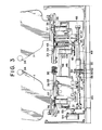
- Figure 3 is a front view of a means for convergence of the setting plate 1, a means for raising and lowering one eye head i.e., a setting plate 1, and a means for adjusting pupillary distance. All such means are assembled in a casing which is fixed on a desk.
- the casing has two horizontal setting boards 39 for left and right eyes, both of which are slidably mounted on the casing by a means described hereinafter.
- Each of the boards 39 has, at each opposite end, a shaft 35, with a convergence plate 33 rotatably mounted on one end thereof, so that the convergence plate 33 can be rotated about the axis defined by the shaft 35.
- Each of the convergence plates 33 has the setting plate 1 which is screwed in place vertically, parallel to the plate 33, at the other end thereof.
- the setting plate 1 has a window 34 for measuring vision data whose center is on the center line of the shaft 35.
- the convergence plate 33 also has a gear 36 fixed to the end carrying the setting plate 1, the gear 36 engaging with a gear 37 attached to a shaft of a direct current motor (DC-motor) 38 fixed to the setting board 39.
- Rotary motion of both convergence plates 33, i.e., convergence of both setting plates 1 is produced by rotation of both DC-motors 38.
- Each of the boards 39 also has a sliding plate 40 which is fixed thereto and slides on a rail 46 fixed to a base 48 by sliding bearings.
- Each of the sliding plates 40 has two actuating pins 47 which are fixed at the bottom portion of 40 and are moved in both directions by the rotation of a leading screw 49, so that each sliding plate 40 slides on rail 46 by rotation of the leading screw 49, which is set by flanges 58 at the sides of the base 48 fixed to the casing, and both leading screws 49 are joined together by a flexible coupling joint 59.
- Attached to the one leading screw 49 are a gear 50 which engages with a gear 52 of a DC-motor 55, and a gear 51 which engages with a gear 53 attached to a shaft of a sensor 54 for showing pupillary distance.
- the sliding plate 40 for the left eye has a mechanism for raising and lowering one eye head, in which a gear 42 attached to a DC-motor 41 fixed to sliding plate 40 engages with a gear 45 attached to a vertical screw 44 engaged with a screw thread on the inside the wall of a cylinder 43 fixed vertically to the setting board 39, so that a rising and falling motion of cylinder 43 i.e., a rising and falling motion of setting board 39 or setting plate 1, is produced by rotation of DC-motor 41.
- Figure 3 does not show bolts and pins for attaching various assemblies of the apparatus.
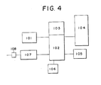
- FIG. 4 is a schematic block diagram showing the elements of an apparatus of this invention.
- 101 is a control switch board
- 102 is a basic board for input and output
- 103 is a basic board for a central processing unit (hereinafter referred to as the CPU)
- 104 is a unit for measuring vision data
- 105 is a monitor
- 106 is a printer
- 107 is an electric power source unit
- 108 is a breaker switch.
- the measuring unit 104 has eight pulse motors, four DC-motors, twelve zero position sensors, and four electro-magnetic clutches.
- Operation of the actuating means can be controlled via the input-output board 102 and the CPU board 103 by control keys or switches 101 on the desk, so that various kinds of vision data of patients can be obtained simply by operation of the switches, and all the data obtained can be digitally displayed in monitor 105 on the desk, and if necessary, can be printed out by printer 106 on the desk.
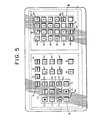
- Figure 5 is a plan view of a control switch board.
- Figure 5 does not show the key or switch for raising and lowering one eye head and the key or switch for adjusting pupillary distance that are associated with the measuring unit 104, but the switches of course may be disposed in the board of Figure 5.
- 60 and 61 are switches for deciding whether the control switches are to be applied to either the right-eye head or the left-eye head.
- 62 and 63 are switches for rotating either clockwise or counterclockwise the pulse motor 9 connected to the spherical lens plate 2.
- Input from the switch 62 or 63 gives a signal to the input-output board 102, while a definite number of pulses are simultaneously sentto the input-output board 102 from CPU board 103 in which a micro-computer is disposed, so that the pulse motor 9 is driven.
- Pushing the switch 62 or 63 once makes lens plate 2 rotate bythe minimum diopter (0.25 d) pitch, and continuing depression of the respective switch or key makes lens plate 2 continue to rotate at a constant speed until actuation of the key or switch is ended.
- current is applied to the electro-magnetic clutch 11, so that lens plate 2.
- the electro-magnetic clutch 11 has a double shaft assembly, either shaft of which is freely rotated independently when the current is cut off, while the double shafts are rotated together like one shaftwhen current is introduced.
- Switch 64 or 65 is the one for rotating the toric lens plates.
- the motion which is produced by actuating these switches is almost the same as the motion in the case of the switches 62 and 63, but the toric lens can only have a cylindrical power of minus diopter, so that the arrow signs on the switches are employed.
- Simultaneous rotation of toric lens plate 15 and 16 is produced by the electro-magnetic clutch 20, as in the case of the spherical lens plates 2 and 3.
- Actuating switch 66 or 67 sends a number of pulses to the pulse motor 28, rotating the cylinder axes of all toric lenses of the toric lens plates 15 and 16 simultaneously in the same direction.
- the motion produced by actuating the switch is the same as with the switches 62 and 63, in that one pitch rotation corresponds to one actuation of the key or switch, and continued actuation produces continuing rotation at a constant speed until the actuation of the switch is ended.
- Pushing a key or switch in the block A in Figure 5 causes the CPU board 103 to judge the number of pulses required, sending a signal to pulse motor 10, and rotating lecos plate 4.
- Each key or switch in the blockA corresponds to each function which is included in an ordinary lecos plate so that 68 is a switch representing cross-line for measuring P.D. which is used in setting pupillary distance.
- 69 or 70 is a switch for closing or opening the measuring window 34.
- 71 or 72 is a switch for Mardoxwhich is used for measuring heterophoria.
- 95 is a switch for retinoscopy which is used for measuring retinoscopy objectively at a distance of 50cm.
- 73 is a switch for a supplementary prism, and 74 is a switch for polaroid lenses, used for binoculartesting.
- 94 is a switch for a fixed crossed- cylinder test for measuring hyperopia which is used for measuring additional diopters for close work.
- 75 is a switch for pin hole which is used for checking amblyopia.
- 92 is a switch for supplementary spherical lenses, used for measuring spherical power of up to +20 D.
- 93 is a switch forsupplemen- tary spherical lenses for intermediate power.
- 76 is a switch which is used for additional diopters necessary for close work, and is actuated to supply direct current to the DC-motor 38 for convergence, converging the convergence plates inward by a necessary angle, simultaneously supplying DC-voltage to the DC-motor 55 for measuring pupillary distance, and making the heads move a few millimeter inward from the pupillary distance for far work.
- 77 is a switch for C sign transposition
- 78 is a switch for printing vision data.
- Switches in block B in Figure 5 are supplementary ones which are used for inputting previously measured data.
- 79 and 80 are switches used for inputting vertical prism power or horizontal prism power.
- 81 and 82 are used for inputting vision power without glasses, and vision power with glasses.
- a key or switch for giving a DC-voltage tothe DC-motor 41 for raising and lowering one eye head disposed in the measuring case or enclosure.
- the switch for givingDC-voltage to the DC-motor 55 for adjusting pupillary distance, moving two heads in an inward or outward direction disposed in the measuring case or enclosure.
- Those switches can of course be included in the switch board of Fig. 5.
- All the data such as data from each lens plate controlled by main switches of the switch board mentioned above, data inputted from supplementary switches of block B, and data from other instruments, can be displayed digitally on a monitor on the desk.
- the data in the monitor can be printed out by a high speed printer, if the switch 78 is pushed. After measuring is finished, the 96 switch is pushed, so that all the measuring means returntotheirzero positions in orderto be ready to the next measurement operation.
Landscapes
- Life Sciences & Earth Sciences (AREA)
- Health & Medical Sciences (AREA)
- Medical Informatics (AREA)
- Biophysics (AREA)
- Ophthalmology & Optometry (AREA)
- Engineering & Computer Science (AREA)
- Biomedical Technology (AREA)
- Heart & Thoracic Surgery (AREA)
- Physics & Mathematics (AREA)
- Molecular Biology (AREA)
- Surgery (AREA)
- Animal Behavior & Ethology (AREA)
- General Health & Medical Sciences (AREA)
- Public Health (AREA)
- Veterinary Medicine (AREA)
- Eye Examination Apparatus (AREA)
Description
- This invention relates to a motor-driven subjective phorometer.
- In prior subjective phorometers, rotary motion of each of their plates which carry respective series of lenses (hereinafter referred to as lens plates) is produced by means of a knob connected directly or by means of gearing to the lens plates. Raising and lowering one of the eye heads, changing the pupillary distance, and causing convergence of the left-eye head and the right-eye head are also effected by knobs. connected thereto by gearing, so that the knobs are mounted separately at different spaced locations, and the data measured therewith must be read off on separate scales and display boards.
- A motor-driven subjective phorometer according to the first portion of Claim 1 is disclosed in EP―A―0,045,897. This known phorometer employs fine stepping motors driven by control and drive signals electronically generated by a computer system. The document does not disclose details on the drive system for moving the lens plates. The mounting means for the lens plates are manually driven in this prior art.
- An object of this invention is to provide a motor-driven subjective phorometer in which all the measuring means can be actuated simply by a group of control switches or keys gathered in a central panel, and all the data measured can be displayed digitally in a monitor and printed as required, while data possessed previously or obtained from other instruments such as an objective phorometer and the like can be inputted thereto simply by the group of control switches or keys.
- This object is achieved with a motor-driven subjective phorometeras claimed in Claim 1.
- An embodiment of the invention will now be described by way of example with reference to the accompanying drawings in which:
- Figures 1A and B are side views of a means for actuating two spherical lens plates, and a means for actuating an additional plate in the right-eye head of a subjective phorometer of this invention, Figure 1A showing the means for actuating a spherical lens plate including a series of spherical lenses-each having a different spherical power, varying in small dioptral steps, and Figure 1B showing the means for actuating a spherical lens plate including a series of spherical lenses each having a different spherical power, varying in large dioptral steps;
- Figures 2A and B are side views of a means for actuating two toric lens plates of the right-eye head of the subjective phorometer of this invention, Figure 2A showing the means for actuating a toric lens plate including a series of toric lenses each having a different cylindrical power, varying in small dioptral steps, and means for actuating a toric lens plate including a series of toric lenses each having a different cylindrical power, varying in large dioptral steps, and Figure 2B showing the means for actuating all the cylinder axes of the toric lenses of the two toric lens plates;
- Figure 3 is a front view of a means for convergence of two plates for the right and left eyes, each plate having all the spherical and toric lens plates mounted thereon, a means for raising or lowering one eye head, and a means for adjusting pupillary distance, of the subjective phorometer;
- Figure 4 is a block diagram of the subjective phorometer; and
- Figure 5 is a plan view of a control key or switch panel of the subjective phorometer.
- The subjective phorometer may be a desk- type apparatus in which all the measuring elements are set on the desk plate or desk top and all the procedures for measuring vision data of eyes are carried out by control keys or switches on the desk, and all the data.measured are displayed digitally on a monitor, and printed out as required.
- The elements of the phorometer for measuring vision data of eyes such as right-eye and left-eye heads each consisting of two spherical lens plates, two toric lens plates, and an additional plate, an element for raising and lowering the one eye head, an element for convergence of the left-eye head and the right-eye head, and an element for adjusting pupillary distance, and so on, are conventional, but the means for actuating those elements and for displaying the data measured are different from the conventional arrangements. The right-eye head and left-eye head are symmetrical relative to each other, so reference will be made to only one eye head hereinafter.
- Figure 1 and Figure 2 are side views of means for driving the elements of the right-eye head. In Figure 1A, 1 is a setting plate. A
lens plate 2 having a circular series of spherical lenses having different spherical powers, varying in 0.25 diopter steps, a lens plate 3 having a circular series of spherical lenses having different spherical powers, varying in 3.00 diopter steps, and anadditional plate 4 having lenses necessary for measuring various kinds of vision data are respectively mounted to a mounting shaft orspindle 5 of the setting plate 1, and are prevented from becoming detached from theshaft 5 by asetting screw 6. - Each
plate shaft 5, and engages arespective gear 7 at its circumference; thegear 7 ofplate 2 engages with thegear 8 fixed to the shaft of apulse motor 9, and thegear 7 of theadditional plate 4 engages with thegear 8 fixed to the shaft of apulse motor 10. - Figure 1 B is a side view of an electro-magnetic clutch assembly for rotating the lens plate 3 as required, in which 11 is an electro-magnetic clutch having a double shaft mechanism, in which the
gear 12 fixed to the shaft of the clutch 11 engages with thegear 7 of thelens plate 2 and thegear 7 of the lens plate 3. - Each
plate shielding plate 13 which serves to detect the zero position of each plate by cooperation with a respective optical sensor 14 (shown in Fig. 2A) which is fixed to the setting plate 1, in association with eachshielding plate 13. - Figure 2A is a side view of a means for driving two toric lens plates, and Figure 2B is a side view of a means for driving the cylinder axes of all the toric lenses of the two toric lens plates. A
lens plate 15 is a toric lens plate having a circular series of five toric lenses each having a different cylindrical power, in 0.25 diopter steps. Alens plate 16 is a toric lens plate having a circular series of toric lenses each having a different cylindrical power, in 1.25 diopter steps.Plates shaft 17 andgears 25, both of which are fixed to the setting plate 1, being prevented from becoming detached by a setting screw 18, and gears 56.Lens plates gear 19 which engages withgear 21 attached to an electro-magnetic clutch 20 which has a double shaft mechanism; thegear 21 also engages with agear 22 attached to the shaft of apulse motor 23. - Each lens in the series of toric lenses arranged in the
lens plates ring 24 which has a gear at the circumference, and the gear of each ring engages with onecentral gear 25 which engages with gear 56 and a connecting gear means 26 which engages with a gear 27 attached to apulse motor 28. - Each of
plates shielding plate 29 which serves to detect the zero position of eachplate optical sensor 31 shown in Figure 1B and attached to the setting plate 1. - Each
plate optical sensor 32 attached to setting plate 1. - Figure 3 is a front view of a means for convergence of the setting plate 1, a means for raising and lowering one eye head i.e., a setting plate 1, and a means for adjusting pupillary distance. All such means are assembled in a casing which is fixed on a desk. The casing has two
horizontal setting boards 39 for left and right eyes, both of which are slidably mounted on the casing by a means described hereinafter. Each of theboards 39 has, at each opposite end, ashaft 35, with aconvergence plate 33 rotatably mounted on one end thereof, so that theconvergence plate 33 can be rotated about the axis defined by theshaft 35. Each of theconvergence plates 33 has the setting plate 1 which is screwed in place vertically, parallel to theplate 33, at the other end thereof. The setting plate 1 has awindow 34 for measuring vision data whose center is on the center line of theshaft 35. Theconvergence plate 33 also has agear 36 fixed to the end carrying the setting plate 1, thegear 36 engaging with agear 37 attached to a shaft of a direct current motor (DC-motor) 38 fixed to thesetting board 39. Rotary motion of bothconvergence plates 33, i.e., convergence of both setting plates 1, is produced by rotation of both DC-motors 38. Each of theboards 39 also has a sliding plate 40 which is fixed thereto and slides on arail 46 fixed to abase 48 by sliding bearings. Each of the sliding plates 40 has two actuatingpins 47 which are fixed at the bottom portion of 40 and are moved in both directions by the rotation of a leadingscrew 49, so that each sliding plate 40 slides onrail 46 by rotation of the leadingscrew 49, which is set byflanges 58 at the sides of thebase 48 fixed to the casing, and both leadingscrews 49 are joined together by aflexible coupling joint 59. Attached to the one leadingscrew 49 are a gear 50 which engages with a gear 52 of a DC-motor 55, and agear 51 which engages with agear 53 attached to a shaft of asensor 54 for showing pupillary distance. The sliding plate 40 for the left eye, shown on the right side in Figure 3, has a mechanism for raising and lowering one eye head, in which agear 42 attached to a DC-motor 41 fixed to sliding plate 40 engages with agear 45 attached to avertical screw 44 engaged with a screw thread on the inside the wall of acylinder 43 fixed vertically to thesetting board 39, so that a rising and falling motion ofcylinder 43 i.e., a rising and falling motion of settingboard 39 or setting plate 1, is produced by rotation of DC-motor 41. Figure 3 does not show bolts and pins for attaching various assemblies of the apparatus. - Figure 4 is a schematic block diagram showing the elements of an apparatus of this invention. In Figure 4, 101 is a control switch board, 102 is a basic board for input and output, 103 is a basic board for a central processing unit (hereinafter referred to as the CPU), 104 is a unit for measuring vision data, 105 is a monitor, 106 is a printer, 107 is an electric power source unit, and 108 is a breaker switch. The
measuring unit 104 has eight pulse motors, four DC-motors, twelve zero position sensors, and four electro-magnetic clutches. Operation of the actuating means can be controlled via the input-output board 102 and theCPU board 103 by control keys orswitches 101 on the desk, so that various kinds of vision data of patients can be obtained simply by operation of the switches, and all the data obtained can be digitally displayed inmonitor 105 on the desk, and if necessary, can be printed out byprinter 106 on the desk. - Figure 5 is a plan view of a control switch board. Figure 5 does not show the key or switch for raising and lowering one eye head and the key or switch for adjusting pupillary distance that are associated with the
measuring unit 104, but the switches of course may be disposed in the board of Figure 5. 60 and 61 are switches for deciding whether the control switches are to be applied to either the right-eye head or the left-eye head. 62 and 63 are switches for rotating either clockwise or counterclockwise thepulse motor 9 connected to thespherical lens plate 2. Input from theswitch output board 102, while a definite number of pulses are simultaneously sentto the input-output board 102 fromCPU board 103 in which a micro-computer is disposed, so that thepulse motor 9 is driven. Pushing theswitch lens plate 2 rotate bythe minimum diopter (0.25 d) pitch, and continuing depression of the respective switch or key makeslens plate 2 continue to rotate at a constant speed until actuation of the key or switch is ended. At the position of just before one revolution oflens plate 2 is completed during the switch actuation operation, current is applied to the electro-magnetic clutch 11, so thatlens plate 2. and lens plate 3 are rotated simultaneously, and the current is cut off after one pitch revolution oflens plates 2 and 3. The electro-magnetic clutch 11 has a double shaft assembly, either shaft of which is freely rotated independently when the current is cut off, while the double shafts are rotated together like one shaftwhen current is introduced. - Switch 64 or 65 is the one for rotating the toric lens plates. The motion which is produced by actuating these switches is almost the same as the motion in the case of the
switches toric lens plate magnetic clutch 20, as in the case of thespherical lens plates 2 and 3. Actuatingswitch 66 or 67 sends a number of pulses to thepulse motor 28, rotating the cylinder axes of all toric lenses of thetoric lens plates switches - Pushing a key or switch in the block A in Figure 5 causes the
CPU board 103 to judge the number of pulses required, sending a signal topulse motor 10, and rotatinglecos plate 4. Each key or switch in the blockA corresponds to each function which is included in an ordinary lecos plate so that 68 is a switch representing cross-line for measuring P.D. which is used in setting pupillary distance. 69 or 70 is a switch for closing or opening the measuringwindow 34. 71 or 72 is a switch for Mardoxwhich is used for measuring heterophoria. 95 is a switch for retinoscopy which is used for measuring retinoscopy objectively at a distance of 50cm. 73 is a switch for a supplementary prism, and 74 is a switch for polaroid lenses, used for binoculartesting. 94 is a switch for a fixed crossed- cylinder test for measuring hyperopia which is used for measuring additional diopters for close work. 75 is a switch for pin hole which is used for checking amblyopia. 92 is a switch for supplementary spherical lenses, used for measuring spherical power of up to +20 D. 93 is a switch forsupplemen- tary spherical lenses for intermediate power. 76 is a switch which is used for additional diopters necessary for close work, and is actuated to supply direct current to the DC-motor 38 for convergence, converging the convergence plates inward by a necessary angle, simultaneously supplying DC-voltage to the DC-motor 55 for measuring pupillary distance, and making the heads move a few millimeter inward from the pupillary distance for far work. 77 is a switch for C sign transposition, and 78 is a switch for printing vision data. - Switches in block B in Figure 5 are supplementary ones which are used for inputting previously measured data. 79 and 80 are switches used for inputting vertical prism power or horizontal prism power. 81 and 82 are used for inputting vision power without glasses, and vision power with glasses. 83, 84, 85, 86, the numeric switches (0)―(9), 87 and 88 are switches which are used to rotate lens plates in orderto set appropriate lenses in front of a patient's eyes when vision data of the patient's eye glasses are previously known. For example, if S=1.00 D, C=0.50 D, and Ax=100°, switches are pushed in the order:
- 83 86 (1) 88 (0) (0) 84 86 (0)
88 (5) (0) 85 (1) (0) (0) 87. Electric power inputted by actuating these switches is applied to the input-output board 102, and then to theCPU board 103, for calculation of the number of pulses to besentto pulse motor 9 in orderto rotate the spherical lens plate, the number of pulses to be sent to thepulse motor 23 in order to rotate the toric lens plate, and the number of pulses to be sent to thepulse motor 28 in order to rotate the cylinder axes; the numbers of pulses calculated are applied to the respective pulse motors for setting each the lens plates and the cylinder axes.Switches CPU board 103, so thatthe number of pulses required is calculated, and sent to the pulse motor, and the lens plates and the cylinder axes are thus set. - In an example of this invention, disposed in the measuring case or enclosure is a key or switch for giving a DC-voltage tothe DC-
motor 41 for raising and lowering one eye head, and the switch for givingDC-voltage to the DC-motor 55 for adjusting pupillary distance, moving two heads in an inward or outward direction. Those switches can of course be included in the switch board of Fig. 5. - All the data such as data from each lens plate controlled by main switches of the switch board mentioned above, data inputted from supplementary switches of block B, and data from other instruments, can be displayed digitally on a monitor on the desk. The data in the monitor can be printed out by a high speed printer, if the
switch 78 is pushed. After measuring is finished, the 96 switch is pushed, so that all the measuring means returntotheirzero positions in orderto be ready to the next measurement operation.
Claims (5)
Applications Claiming Priority (2)
| Application Number | Priority Date | Filing Date | Title |
|---|---|---|---|
| JP109451/82 | 1982-06-25 | ||
| JP57109451A JPS5937A (en) | 1982-06-25 | 1982-06-25 | Self-conscious type electromotive opthalmscope |
Publications (3)
| Publication Number | Publication Date |
|---|---|
| EP0098442A2 EP0098442A2 (en) | 1984-01-18 |
| EP0098442A3 EP0098442A3 (en) | 1984-07-18 |
| EP0098442B1 true EP0098442B1 (en) | 1987-03-11 |
Family
ID=14510565
Family Applications (1)
| Application Number | Title | Priority Date | Filing Date |
|---|---|---|---|
| EP83106014A Expired EP0098442B1 (en) | 1982-06-25 | 1983-06-20 | A motor-driven subjective phorometer |
Country Status (6)
| Country | Link |
|---|---|
| US (1) | US4537480A (en) |
| EP (1) | EP0098442B1 (en) |
| JP (1) | JPS5937A (en) |
| AU (1) | AU554519B2 (en) |
| CA (1) | CA1208953A (en) |
| DE (1) | DE3370133D1 (en) |
Families Citing this family (7)
| Publication number | Priority date | Publication date | Assignee | Title |
|---|---|---|---|---|
| JPS61293422A (en) * | 1985-06-22 | 1986-12-24 | 株式会社トプコン | Self-conscious eye examination apparatus |
| JPH0418568Y2 (en) * | 1987-12-22 | 1992-04-24 | ||
| JPH0316903U (en) * | 1989-07-04 | 1991-02-20 | ||
| JPH0811075Y2 (en) * | 1993-02-15 | 1996-03-29 | 株式会社ニデック | Subjective optometry device |
| JP3953977B2 (en) * | 2003-04-30 | 2007-08-08 | 株式会社ニデック | Optometry equipment |
| US8786210B2 (en) | 2010-06-30 | 2014-07-22 | Welch Allyn, Inc. | Drive circuit for light emitting diode |
| US20240192462A1 (en) * | 2022-12-09 | 2024-06-13 | Apple Inc. | Electronic Devices With Movable Optical Assemblies |
Family Cites Families (9)
| Publication number | Priority date | Publication date | Assignee | Title |
|---|---|---|---|---|
| US3498699A (en) * | 1967-06-13 | 1970-03-03 | American Optical Corp | Refractor |
| DE1955859C3 (en) * | 1969-11-06 | 1982-04-08 | Fa. Carl Zeiss, 7920 Heidenheim | Device for determining the refractive state of an eye |
| US3969020A (en) * | 1973-12-28 | 1976-07-13 | Giles C. Clegg, Jr. | Automatic refraction apparatus and method |
| JPS6043133B2 (en) * | 1977-04-20 | 1985-09-26 | 東京光学機械株式会社 | automatic optometry device |
| DE2901459C2 (en) * | 1979-01-16 | 1984-07-12 | J.D. Möller Optische Werke GmbH, 2000 Wedel | Phoropters |
| DD146888A1 (en) * | 1979-11-01 | 1981-03-11 | Rolf Boerner | BRILLENBESTIMMUNGSGERAET |
| FR2486795A1 (en) * | 1980-07-21 | 1982-01-22 | France Etat | OBJECTIVE REFRACTOMETER ASSISTED BY MICROPROCESSOR |
| EP0045897A3 (en) * | 1980-08-11 | 1982-03-24 | BAUSCH & LOMB INCORPORATED | Compact refraction instrument |
| US4436390A (en) * | 1981-02-16 | 1984-03-13 | Tokyo Kogaku Kikai Kabushiki Kaisha | Ophthalmic instrument having a cross cylinder lens |
-
1982
- 1982-06-25 JP JP57109451A patent/JPS5937A/en active Pending
-
1983
- 1983-06-01 US US06/500,069 patent/US4537480A/en not_active Expired - Fee Related
- 1983-06-06 CA CA000429732A patent/CA1208953A/en not_active Expired
- 1983-06-20 EP EP83106014A patent/EP0098442B1/en not_active Expired
- 1983-06-20 DE DE8383106014T patent/DE3370133D1/en not_active Expired
- 1983-06-24 AU AU16258/83A patent/AU554519B2/en not_active Ceased
Also Published As
| Publication number | Publication date |
|---|---|
| AU1625883A (en) | 1984-01-05 |
| AU554519B2 (en) | 1986-08-21 |
| EP0098442A2 (en) | 1984-01-18 |
| DE3370133D1 (en) | 1987-04-16 |
| JPS5937A (en) | 1984-01-05 |
| EP0098442A3 (en) | 1984-07-18 |
| US4537480A (en) | 1985-08-27 |
| CA1208953A (en) | 1986-08-05 |
Similar Documents
| Publication | Publication Date | Title |
|---|---|---|
| US4500180A (en) | Motorized refraction apparatus | |
| US4798457A (en) | Self-conscious type eye examining apparatus | |
| US4496226A (en) | ANDed motor control system for motorized ophthalmic instrument | |
| US3891311A (en) | Multiparameter vision testing apparatus | |
| US5223864A (en) | Phoropter | |
| JPH021214A (en) | Apparatus for measuring pupillary distance | |
| JPH05176893A (en) | Subjective ophthalmoscopic apparatus | |
| US5617157A (en) | Computer controlled subjective refractor | |
| EP0098442A2 (en) | A motor-driven subjective phorometer | |
| US5537248A (en) | Accessory module for a stereo microscope | |
| US4426140A (en) | Refractor suspension system | |
| US7144112B2 (en) | Optometric apparatus | |
| EP0143151A2 (en) | Apparatus for use in an ophthalmic instrument | |
| US4142139A (en) | Search mount for telescope and method of operation | |
| CN2326935Y (en) | Fully-automatic measuring locater | |
| JPH05253186A (en) | Optometry system | |
| CA1167300A (en) | Motor control system for motorized ophthalmic instrument | |
| JP2816148B2 (en) | How to use the convergence device of the subjective eye refractive power measurement device when measuring the near point | |
| JP4498544B2 (en) | A subjective optometry device | |
| JPH0345685Y2 (en) | ||
| JPH0352489Y2 (en) | ||
| JP3445639B2 (en) | Subjective optometry device | |
| EP0667116A1 (en) | Phase-contrast haploscope comprising a rotary disc | |
| JPH05168593A (en) | Sebjective ophthalmoscopic device | |
| JPH08317899A (en) | Aware optometry device |
Legal Events
| Date | Code | Title | Description |
|---|---|---|---|
| PUAI | Public reference made under article 153(3) epc to a published international application that has entered the european phase |
Free format text: ORIGINAL CODE: 0009012 |
|
| AK | Designated contracting states |
Designated state(s): DE FR GB IT SE |
|
| PUAL | Search report despatched |
Free format text: ORIGINAL CODE: 0009013 |
|
| RHK1 | Main classification (correction) |
Ipc: A61B 3/04 |
|
| AK | Designated contracting states |
Designated state(s): DE FR GB IT SE |
|
| 17P | Request for examination filed |
Effective date: 19850102 |
|
| GRAA | (expected) grant |
Free format text: ORIGINAL CODE: 0009210 |
|
| AK | Designated contracting states |
Kind code of ref document: B1 Designated state(s): DE GB |
|
| RAP2 | Party data changed (patent owner data changed or rights of a patent transferred) |
Owner name: HOYA CORPORATION |
|
| REF | Corresponds to: |
Ref document number: 3370133 Country of ref document: DE Date of ref document: 19870416 |
|
| PLBE | No opposition filed within time limit |
Free format text: ORIGINAL CODE: 0009261 |
|
| STAA | Information on the status of an ep patent application or granted ep patent |
Free format text: STATUS: NO OPPOSITION FILED WITHIN TIME LIMIT |
|
| 26N | No opposition filed | ||
| PGFP | Annual fee paid to national office [announced via postgrant information from national office to epo] |
Ref country code: GB Payment date: 19920610 Year of fee payment: 10 |
|
| PGFP | Annual fee paid to national office [announced via postgrant information from national office to epo] |
Ref country code: DE Payment date: 19920626 Year of fee payment: 10 |
|
| PG25 | Lapsed in a contracting state [announced via postgrant information from national office to epo] |
Ref country code: GB Effective date: 19930620 |
|
| GBPC | Gb: european patent ceased through non-payment of renewal fee |
Effective date: 19930620 |
|
| PG25 | Lapsed in a contracting state [announced via postgrant information from national office to epo] |
Ref country code: DE Effective date: 19940301 |