EP0098254A2 - A weft reservoir for fluid jet looms - Google Patents
A weft reservoir for fluid jet looms Download PDFInfo
- Publication number
- EP0098254A2 EP0098254A2 EP83850181A EP83850181A EP0098254A2 EP 0098254 A2 EP0098254 A2 EP 0098254A2 EP 83850181 A EP83850181 A EP 83850181A EP 83850181 A EP83850181 A EP 83850181A EP 0098254 A2 EP0098254 A2 EP 0098254A2
- Authority
- EP
- European Patent Office
- Prior art keywords
- weft
- reservoir
- control pin
- cam
- control
- Prior art date
- Legal status (The legal status is an assumption and is not a legal conclusion. Google has not performed a legal analysis and makes no representation as to the accuracy of the status listed.)
- Withdrawn
Links
Images



Classifications
-
- D—TEXTILES; PAPER
- D03—WEAVING
- D03D—WOVEN FABRICS; METHODS OF WEAVING; LOOMS
- D03D47/00—Looms in which bulk supply of weft does not pass through shed, e.g. shuttleless looms, gripper shuttle looms, dummy shuttle looms
- D03D47/34—Handling the weft between bulk storage and weft-inserting means
-
- D—TEXTILES; PAPER
- D03—WEAVING
- D03D—WOVEN FABRICS; METHODS OF WEAVING; LOOMS
- D03D47/00—Looms in which bulk supply of weft does not pass through shed, e.g. shuttleless looms, gripper shuttle looms, dummy shuttle looms
- D03D47/34—Handling the weft between bulk storage and weft-inserting means
- D03D47/36—Measuring and cutting the weft
- D03D47/361—Drum-type weft feeding devices
- D03D47/362—Drum-type weft feeding devices with yarn retaining devices, e.g. stopping pins
-
- D—TEXTILES; PAPER
- D03—WEAVING
- D03D—WOVEN FABRICS; METHODS OF WEAVING; LOOMS
- D03D47/00—Looms in which bulk supply of weft does not pass through shed, e.g. shuttleless looms, gripper shuttle looms, dummy shuttle looms
- D03D47/34—Handling the weft between bulk storage and weft-inserting means
- D03D47/36—Measuring and cutting the weft
- D03D47/361—Drum-type weft feeding devices
- D03D47/362—Drum-type weft feeding devices with yarn retaining devices, e.g. stopping pins
- D03D47/363—Construction or control of the yarn retaining devices
Definitions
- the side of the device closer to the supply source of weft is referred to as “the upstream side” and the side of the device closer to the main jet nozzle is referred to as “the downstream side”.
- control pin leaves its operative zone by disappearing from the periphery of the reservoir drum, and advances into its operative zone by appearing on the periphery of the reservoir drum.
- weft reservoir can well be used for weaving by one sort of weaving, too.
- a magazine 41 is arranged on the outer side of the reservoir drum 1 in a fixed relationship, and a slot 41a is formed in the wall of magazine 41 facing the reservoir drum 1 whilst extending in the axial direction of the reservoir drum 1.
- the first control pin P1 is directed towards the reservoir drum 1 through this slot 41a and its drive cam Cl is encased within the magazine 41.
- Each of the drive cams C1 and C2 completes its one cycle rotation within a period of 0° to 1080° crank angle, weft delivery for the first weft insertion is carried out within a period of 0° to 360 crank angle and weft delivery for the second insertion is carried out within a period of 360 to 720° crank angle, on one weft reservoir. During a period of 720° to 1080 crank angle, weft delivery for insertion is carried out once on the other weft reservoir.
- each of the drive cams C1 and C2 completes its one cycle rotation within a period of 0 to 1440° crank angle and weft delivery for insertion is carried out twice within a period of 0° to 720 crank angle on one weft reservoir.
- weft delivery for insertion is carried out twice on the other weft reservoir.
- a moment (I) in Fig. 2 corresponds to 0° crank angle.
- the first control pin P1 stays standstill at the most advanced position in its operative zone whereas the second control pin P2 has already started to recede from the most advanced position in its operative zone in order to move downstream along an arc path of travel in the axial direction of the reservoir drum 1.
- Reservation of weft for the second insertion has already started on the upstream side of the first control pin P1 and coils of weft for the first insertion are reserved in the area between the first and second control pins P1 and P2.
- a moment (DI) in Fig. 2 corresponds to 180 0 crank angle.
- a moment X in Fig. 2 corresponds to 810 crank angle and shift in condition from this moment corresponds to that from the moment (IV) to the moment (VI).
- the first control pin P1 starts to recede from the most advanced position in the operative zone to travel downstream whereas the second control pin P2 starts to advance from the most receded position in the stand-by zone. Reservation of weft further develops on the upstream side of the first control pin P1.
- the coils of reserved weft are always assigned from the first to second control pin at the same axial position on the reservoir drum whereat the two control pins pass by.
- This similarity in assignment of reserved weft relates to similarity in mode of reservation of weft for the first and second insertions.
- Such similar mode of reservation of weft at different moments relates to similar behaviour of weft during delivery of weft at different moment.
- Uniform insertion can be carried out for every cycle of loom running. This is the:biggest advantage of the present invention.
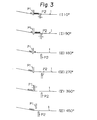
- FIG. 3 The other example of the operation of the weft reservoir in accordance with the present invention is shown in Fig. 3, in which, like the first example, four coils of weft are assumed to correspond to the length of weft for one insertion of weft, black circles indicate coils of weft for the first insertion of weft, and white circles indicate coils of weft for the second insertion of weft.'
- a moment (I) in Fig. 3 corresponds to 0° crank angle.
- the first control pin P1 is located within the operative zone and the second control pin P2 has started to recede from the most advanced position in the operative zone to move downstream along an arc path of travel in the axial direction of the weft reservoir 1. Reservation of weft for the second insertion has already started on the upstream side of the first control pin P1 and coils of weft for the first insertion are held in the area between the two control pins P1 and P2.
- the second control pin P2 has just disappeared from the periphery of the reservoir drum 1. Delivery of weft for the first insertion now starts. Reservation of weft further continues on the upstream side of the first control pin P1 and the coils of weft, which have been held in the area between the first and second control pins, are sequentially delivered due to traction by the main jet nozzle which has started the first insertion of weft.
- a moment (VI) in Fig. 3 corresponds to 450 crank angle.
- the first control pin P1 has reached the most receded position in the stand-by zone and the second control pin P2 remains standstill at the most receded position in the stand-by zone.
- the second insertion of weft starts at this moment.
- the coils of weft which have been held by the first control pin P1 are sequentially delivered due to traction of the main jet nozzle.
- the first control pin P1 has already been registered at the most advanced position in the operative zone and the position of the second control pin P2 is unchanged.
- the second insertion of weft terminates about this moment and reservation of weft for the first insertion of the next cycle has already started on the upstream side of the first control pin Pl.
- This condition is maintained at the moment (IX) in Fig. 3 corres- ponding to 720 crank angle and the above-described reservation of weft further develops.
- a moment (XI) in Fig. 3 corresponds to 900 crank angle.
- the first control pin P1 traveling downstream passes by the second control pin P2 traveling upstream and coils of weft for the first insertion of the next cycle, which have been held on the upstream side of the first control pin Pl, are assigned to the second control pin P2 at this very moment of passing by. Assignment of reserved weft takes place between the first and second control pins P1 and P2.
- the first control pin P1 is now registered at the most receded position in the stand-by zone whereas the second control pin P2 is registered at the most advanced position in the operative zone.
Landscapes
- Engineering & Computer Science (AREA)
- Textile Engineering (AREA)
- Looms (AREA)
Abstract
In construction of a pin control type weft reservoir for fluid jet looms, inter-pin assignment of weft on a reservoir drum is carried out when a pair of control pins pass by each other during their movement in the axial direction of the reservoir drum each along an arc path of travel in advance to delivery of weft for insertion so that the inter-pin assignment should take place at a constant location with a constant distance of weft displacement for uniform and stable transportation of weft through sheds from insertion to insertion.
Description
- The present invention relates to a weft reservoir for fluid jet looms, and more particularly relates to improvement in construction and operation of a weft reservoir for fluid jet looms on which weft is wound about a reservoir drum made up of conical and cylindrical sections by operation of a rotary yarn guide synchronized with loom running, and reserved thereon and delivered therefrom for insertion of weft under pin control.
- In the following description, the side of the device closer to the supply source of weft is referred to as "the upstream side" and the side of the device closer to the main jet nozzle is referred to as "the downstream side".
- Insertion of weft in general starts at a moment between 90° and 110 crank angle and terminates at a moment between 250° and 270 crank angle. First, the weft is unwound from the reservoir drum by free delivery and the so-called controlled delivery of weft starts just before the end of the insertion.
- For simplification purposes, it is,however,assumed here that insertion of weft should start at about 90° crank angle and terminates at about 270° crank angle.
- When a control pin is located within its operative zone, the control pin comes in engagement with a weft on the reservoir drum and hinders its delivery from the reservoir drum. When a control pin is located within its stand-by zone, the control pin stays out of engagement with a weft on the reservoir drum and allows delivery of the weft from the reservoir drum. More specifically, a control pin first recedes from the most advanced positiion in the operative zone, leaves the operative zone while intruding into the stand-by zone, and arrives at the most receded position in the stand-by zone. On return route, the control pin advances from the most receded position in the stand-by zone, leaves the stand-by zone while intruding into the operative zone, and returns to the most advanced position in the operative zone.
- In the case of a weft reservoir on which a control pin or pins are arranged inside a reservoir drum, the control pin leaves its operative zone by disappearing from the periphery of the reservoir drum, and advances into its operative zone by appearing on the periphery of the reservoir drum.
- A weft reservoir for two-pick alternate weaving provided with three control pins has already been proposed. Briefly speaking, this conventional construction includes the first to third control pins arranged one after another in the axial direction of the reservoir drum so that each of them should be driven, by a suitable cam drive, for reciprocation along an arc path of travel in the axial direction of the reservoir drum. Assignment of weft is carried out when two of the control pins pass by while moving along the above-described arc paths of travel. More specifically, a weft held by the first control pin is taken over by the third control pin and a weft held by the second control pin is also taken over by the third control pin.
- In the weft reservoir of this type, coils of weft reserved on the reservoir drum shift downstream in advance to the following delivery of weft from the reservoir drum. Since this movement of weft is carried out under pin control, the coils of weft move very smoothly on the reservoir drum without any danger of impulsive damage.
- This conventional system, however, includes two sorts of alternate inter-pin assignment of weft. That is, one is from the first to third control pin and the other from the second to third control pin. Different assignments of weft have different areas and distances of movement of weft. As a consequence, the posture of weft on the reservoir drum just before delivery varies from insertion to insertion and this relates to unavoidable variation in transportation of weft during insertion. In addition, the mode of cam drive
- needs to vary from pin to pin and, consequently, coordination of cam drive for three cooperating control pins inevitably requires highly complicated construction of the device.
- It is one-object-of the present invention to provide an improved weft reservoir for fluid jet looms which assures stable, and uniform transportation of weft from insertion to insertion.
- It is another object of the present invention to provide an improved weft reservoir for fluid jet looms which uses only two control pins but has a function substantially similar to that of the conventional weft reservoir using three control pins.
- It is the other object of the present invention to provide an improved weft reservoir for fluid jet looms on which the number of transfer of weft during reservation is greatly reduced.
- In accordance with one aspect of the present invention, a pair of cam driven control pins are arranged one after another in the axial direction of a reservoir drum each for timed movement along an arc path of travel in the axial direction of the reservoir drum between operative and stand-by zones. When the control pins pass by each other on their courses of travel, coils of weft are always assigned from the first to second control pin.
- In accordance with the other aspect of the present invention, a pair of control pins are cam driven for movement each along an arc path of travel in the axial direction of the reservoir drum so that, when the control pins pass by each other on their courses of travel, coils of weft for the first insertion of weft only are assigned from the first to second control pin.
- One embodiment of the weft reservoir in accordance with the present invention is shown in Fig. 1, in which a stationary reservoir drum is used. Needless to say, the present invention is well applicable to a weft reservor with a rotary reservoir drum,--too.
- Although use of the weft reservoir is hereinafter explained in connection with alternate weaving by two sorts of wefts, the weft reservoir can well be used for weaving by one sort of weaving, too.
- In the construciton of the following weft reservoir, the upstream side first control pin moves with respect to a reservoir drum on the outer side of the reservoir drum whereas the downstream side second control pin moves with respect to the reservoir drum on the inner side of the reservoir drum. But their arrangement is not limitted to this example. The first control pin may move on the inner side and the second control pin on the outer side of the reservoir drum. Both of them may be arranged either on the outer or on the inner side of the reservoir drum.
- The
reservoir drum 1 includes an upstream side conical section la, a downstream sidecylindrical section 1b and a slot lc which extends in the axial direction of thereservoir drum 1 in the area astride the conical and cylindrical sections la and 1b. - A
magazine 41 is arranged on the outer side of thereservoir drum 1 in a fixed relationship, and aslot 41a is formed in the wall ofmagazine 41 facing thereservoir drum 1 whilst extending in the axial direction of thereservoir drum 1. The first control pin P1 is directed towards thereservoir drum 1 through thisslot 41a and its drive cam Cl is encased within themagazine 41. - A
support shaft 43 is fixed within themagazine 41 whilst extending in a direction substantially normal to the axial direction of thereservoir drum 1, and abifurcate lever 46 is idly inserted,at its middle,over thesupport.shaft 43. Thefirst branch 46a of thebifurcate lever 46 extends through theslot 41a and, at its distal end, firmly holds the first control pin P1, whereas thesecond branch 46b rotatably carries acam follower 48. Aspring seat 51 is properly formed on thesecond branch 46b of thebifurcate lever 46 and atension spring 54 is interposed between thisspring seat 51 and anotherspring seat 52 properly formed within themagazine 41. - A
cam shaft 56 is rotatably arranged within themagazine 41 substantially in parallel to thesupport shaft 43 for thebifurcate lever 46 and the above-described drive cam C1 for the first control pin P1 is fixedly mounted on thiscam shaft 56. Only a part of the cam profile is illustrated in the drawing for simplification purposes. Thecam shaft 56 is operationally coupled in a known manner to a proper outside drive source, such as a drive shaft (not shown) for arotary yarn guide 21 of the weft reservoir, for rotation synchronized with running of the loom. By operation of thetension spring 54, thecam follower 48 is always kept in resilient pressure contact with periphery of the drive cam Cl so taht the first control pin P1 should be driven for an arc movement around thesupport shaft 43 as the.cam Cl rotates. - A
support shaft 4 is secured to aninside framework 3 of thereservoir drum 1 whilst extending in a direction substantially normal to the axial direction of the latter, and abifurcate lever 7 is idly inserted, at its middle, over thesupport shaft 4. Thefirst branch 7a of thisbifurcate lever 7 firmly holds, at its distal end, the second control pin P2 directed towards the periphery of thereservoir drum 1, whereas thesecond branch 7b rotatably carries a cam follower 8. Aspring seat 9 is properly formed on thesecond branch 7b of thebifurcate lever 7, and a compression spring 11 is interposed between thisspring seat 9 and another spring seat (not shown) properly arranged on theinside framework 3. - A
cam shaft 19 is rotatably mounted inside theframework 3 substantially in parallel to the above-describedsupport shaft 4, and a drive cam C2 for the second control pin P2 is securedly mounted on thiscam shaft 19. Only a part of the cam profile is illustrated for simplification purposes. The cam follower 8 is always kept in resilinet pressure contact with the drive cam C2 by operation of the compression spring 11. As the drive cam C2 rotates, the second control pin P2 is driven for a movement around thesupport shaft 4. - Operation of the weft reservoir in accordance with.the present invention will hereinafter be explained in reference to a 2x1 type alternate weaving in which two wefts of the first sort and one weft of the second sort are inserted alternately. That is, if two sorts of wefts A and B are used, weft insertion is carried out in the order of A, A, B, A, A, B. To this end, two sets of weft reservoirs are used in combination. Each of the drive cams C1 and C2 completes its one cycle rotation within a period of 0° to 1080° crank angle, weft delivery for the first weft insertion is carried out within a period of 0° to 360 crank angle and weft delivery for the second insertion is carried out within a period of 360 to 720° crank angle, on one weft reservoir. During a period of 720° to 1080 crank angle, weft delivery for insertion is carried out once on the other weft reservoir.
- In the case of a 2x2 type alternate weaving in which two wefts of the first sort and two wefts of the second sort are inserted alternately, each of the drive cams C1 and C2 completes its one cycle rotation within a period of 0 to 1440° crank angle and weft delivery for insertion is carried out twice within a period of 0° to 720 crank angle on one weft reservoir. During a period of 720° to 1440° crank angle, weft delivery for insertion is carried out twice on the other weft reservoir.
- Depending on the type of alternate weaving by two sorts of wefts, the center angle of each drive cam corresponding to • the period of 0 to 720 crank angle varies. However, the occupation ratio of the high (or low) section of the drive cam and the timing of shift from the high to low section of the drive cam are not influenced at all by the type alternate weaving.
- One example of the operation of the weft reservoir in accordance with the present invention is shown in Fig. 2, in which four coils of weft are assumed to correspond to the length of weft for one insertion of weft. Further in the illustration, black circles indicate coils of weft for the first insertion of weft and white circles indicate coils of weft for the second insertion of weft.
- A moment (I) in Fig. 2 corresponds to 0° crank angle. At this moment, the first control pin P1 stays standstill at the most advanced position in its operative zone whereas the second control pin P2 has already started to recede from the most advanced position in its operative zone in order to move downstream along an arc path of travel in the axial direction of the
reservoir drum 1. Reservation of weft for the second insertion has already started on the upstream side of the first control pin P1 and coils of weft for the first insertion are reserved in the area between the first and second control pins P1 and P2. - A moment (II) in Fig. 2 corresponds to 900 crank cycle. At this moment; the first control pin P1 still stays at the most advanced position in its operative zone whereas the second control pin P2, as a result of its continued recession, has just left the operative zone. More specifically, the second control pin P2 has disappeared from the periphery of the
reservoir drum 1. Delivery of weft for the first insertion starts at this moment. As a consequence, the coils of weft reserved in the area between the first and second control pins P1 and P2 are delivered in sequence due to traction by the main jet nozzle which has started the first insertion of weft, though reservation of weft further continues on the upstream side of the first control pin Pl. - A moment (DI) in Fig. 2 corresponds to 1800 crank angle.
- The first control pin P1 remains standstill at the most advanced position in the operative zone and the second control pin P2 has already arrived at the most receded position in the stand-by zone. Reservation of weft on the upstream side and delivery of weft on the downstream side of the first control pin P1 both further continue at this moment.
- A moment (IV) in Fig. 2 corresponds to 270 crank angle. About this moment, the first control pin P1 starts to recede from the most advanced position in its operative zone in order to move downstream. Concurrently with this, the second control pin P2 starts to advance from the most receded position in its stand-by zone in order to travel upstream in the axial direction of the
reservoir drum 1. The first insertion of weft terminates about this moment. Reservation of weft is further developing on the upstream side of the first control pin P1 and no coil of weft now remains on the downstream side. - A moment (V) in Fig. 2 corresponds to 360° crank angle. Somewhat before this moment, the first control pin P1 traveling downstream passes by the second control pin P2 traveling upstream, and the coils of weft for the second insertion, which have been reserved on the upstream side of the first control pin P1, are assigned to the second control pin P2 at this very moment of passing by. In other words, assignment of reserved weft takes place between the first and second control pins Pl and P2. Since this assignment of reserved weft is carried out when the two control pins Pl and P2 get closest to each other, coils of weft are least disturbed in posture at the assignment. In other words, assignment of reserved weft can be significantly stabilized.
- At the moment (V), the first control pin P1 stays stand- still at the most receded position in its stand-by zone whereas the second control pin P2 also stays standstill but at the most advanced position in its operative zone. More specifically, the first control pin Pl is located radially outside the cylindrical section lb of the
reservoir drum 1 and the second control pin P2 is located about the border between the conical and cylindrical sections la and lb. Coils of weft for the second insertion are now reserved on the upstream side of the second control pin P2. - A moment (VI) in Fig. 2 corresponds to 450 crank angle. Slightly before this moment, the first control pin P1 starts to advance from the most receded position in the stand-by zone to move upstream and the second control pin P2 starts to recede from the most advanced position in the operative zone to travel downstream while accompanying the coils of weft on the upstream side. At this very moment (VI), delivery of weft for the second insertion is on the verge of start. That is, the first control pin P1 has just intruded into the operative zone and the second control pin P2 is on the verge of leaving from the operative zone. The coils of weft are still held on the upstream side of the second control pin P2.
- A moment (VII) in Fig. 2 corresponds to 540° crank angle. The first control pin P1 stays standstill at the most advanced position in the operative zone whereas the second control pin P2 stays standstill at the most receded position in the stand-by zone. The positions of the two control pins P1 and P2 at this moment are the same as those at the moment III. Reservation of weft for the first insertion of the next cycle has ready started on the upstream side and delivery of weft for the second insertion has already started on the downstream side of the first control pin Pl.
- A moment (VIII) in Fig. 2 corresponds to 630 crank angle. The first and second control pins P1 and P2 both retains their positions at the moment (VII). The second insertion of weft has already terminated at this moment. Reservation of weft develops on the upstream side of the first control pin P1.
- This condition is maintained also at a moment (IX) in Fig. 2 which corresponds to 7200 crank angle.
- 0 A moment X in Fig. 2 corresponds to 810 crank angle and shift in condition from this moment corresponds to that from the moment (IV) to the moment (VI). About this moment, the first control pin P1 starts to recede from the most advanced position in the operative zone to travel downstream whereas the second control pin P2 starts to advance from the most receded position in the stand-by zone. Reservation of weft further develops on the upstream side of the first control pin P1.
- A moment (XI) in Fig. 2 corresponds to 900 crank angle. Somewhat before this moment, the first control pin P1 traveling downstream passes by the second control pin P2 traveling upstream, and coils of weft for the first insertion of the next cycle, which have been held on the upstream side of the first control pin P1, are assigned to the second control pin P2 at this very moment of passing by. In other words, assignment of reserved weft takes place between the first and second control pins P1 and P2.
- In the case of the assignment of reserved weft preceding the moment (V), coils of weft for the second insertion are assigned from the first to second control pin. Whereas, in the case of the assignment of reserved weft preceding the moment (XI), coils of weft for the first insertion of the next cycle are assigned from the first to second control pin.
- In either case, the coils of reserved weft are always assigned from the first to second control pin at the same axial position on the reservoir drum whereat the two control pins pass by. This similarity in assignment of reserved weft relates to similarity in mode of reservation of weft for the first and second insertions. Such similar mode of reservation of weft at different moments relates to similar behaviour of weft during delivery of weft at different moment. Uniform insertion can be carried out for every cycle of loom running. This is the:biggest advantage of the present invention.
- 0 Finally, a moment (XII) in Fig. 2 correspond to 990 crank angle. Slightly before this moment, the first control pin P1 starts to advance from the most receded position in the stand-by zone to travel upstream and the second control pin P2 starts to recede from the most advanced position in the operative zone to move downstream. The first control pin P1 traveling upstream and the second control pin P2 traveling downstream pass by.
- At the moment (XII), as a consequence, the first control pin P1 has intruded into the operative zone and the second control pin P2 is on the verge of leaving the operative zone, the coils of weft are.still being held on the upstream side of the second control pin P2. Then the whole reverts to the situation at the moment (I) in Fig. 2 and the next cycle of loom running starts.
- In the case of the weft reservoir having the operation exemplified in Fig. 2, drive cams C1 and C2 for the first and second control pins P1 and P2 are designed and phased from each other so that coils of weft for the first and second insertions are both assigned between the two control pins P1 and P2 at the same axial position on the reservoir drum.
- The other example of the operation of the weft reservoir in accordance with the present invention is shown in Fig. 3, in which, like the first example, four coils of weft are assumed to correspond to the length of weft for one insertion of weft, black circles indicate coils of weft for the first insertion of weft, and white circles indicate coils of weft for the second insertion of weft.'
- A moment (I) in Fig. 3 corresponds to 0° crank angle. The first control pin P1 is located within the operative zone and the second control pin P2 has started to recede from the most advanced position in the operative zone to move downstream along an arc path of travel in the axial direction of the
weft reservoir 1. Reservation of weft for the second insertion has already started on the upstream side of the first control pin P1 and coils of weft for the first insertion are held in the area between the two control pins P1 and P2. - A moment (II) in Fig. 3 corresponds to 900 crank angle. The first control pin P1 still remains in the operative zone but the second control pin P2 has just left the operative zone.
- More specifically, the second control pin P2 has just disappeared from the periphery of the
reservoir drum 1. Delivery of weft for the first insertion now starts. Reservation of weft further continues on the upstream side of the first control pin P1 and the coils of weft, which have been held in the area between the first and second control pins, are sequentially delivered due to traction by the main jet nozzle which has started the first insertion of weft. - A moment (III) in Fig. 3 corresponds to 180° crank angle. The first control pin P1 stays standstill in the operative zone and the second control pin P2 in the stand-by zone. This condition is maintained at a moment (IV) in Fig. 3 corresponding to 270° crank angle, and reservation of weft further develops on the upstream side of the first control pin P1. The first insertion of weft terminates about the moment (IV).
- A moment (V) in Fig. 3 corresponds to 360° crank angle. Slightly before this moment, the first pin P1 has started to recede from the most advanced position to move downstream along an arc path of travel in the axial direction of the
reservoir drum 1 and, at the moment (V), is just going to leave the operative zone. The second control pin P2 remains stand-still at the most receded position in the stand-by zone. Coils of weft are held on the upstream side of the first control pin P1 for use at the second insertion of weft. - A moment (VI) in Fig. 3 corresponds to 450 crank angle. The first control pin P1 has reached the most receded position in the stand-by zone and the second control pin P2 remains standstill at the most receded position in the stand-by zone. The second insertion of weft starts at this moment. As a consequence, the coils of weft, which have been held by the first control pin P1, are sequentially delivered due to traction of the main jet nozzle.
- The process from the moment (IV) to the moment (VI) in this example should be compared with that from the moment (IV) to the moment (VI) in the preceding example shown in Fig. 2. In the case of the preceding example shown in Fig. 2, coils of weft for the second insertion are once assigned from the first to second control pin P2 in advance to delivery from the
reservoir drum 1. In the case of the example shown in Fig. 3, coils of weft are released from hold by the first control pin Pl and directly subjected to delivery from thereservoir drum 1 without any inter-pin assignment. - A moment (VII) in Fig. 3 corresponds to 540° crank angle. The first control pin P1 has already started to advance from the most receded position in the stand-by zone and the second control pin P2 remains standstill in the stand-by zone.
- 0 A moment (VIII) in Fig. 3 corresponds to 630 crank angle.
- The first control pin P1 has already been registered at the most advanced position in the operative zone and the position of the second control pin P2 is unchanged. The second insertion of weft terminates about this moment and reservation of weft for the first insertion of the next cycle has already started on the upstream side of the first control pin Pl. This condition is maintained at the moment (IX) in Fig. 3 corres- ponding to 720 crank angle and the above-described reservation of weft further develops.
- A moment (X) in Fig. 3 corresponds to 8100 crank angle. The first control pin P1 has already started to recede from the most advanced position in the operative zone and, at this moment, is just going to leave the operative zone. Concurrently, the second control pin P2 has already started to advance from the most receded position in the stand-by zone and, at this moment, is on the verge of intrusion into the operative zone. Reservation of weft further continues on the upstream side of the first control pin P1.
- A moment (XI) in Fig. 3 corresponds to 900 crank angle. Somewhat before this moment, the first control pin P1 traveling downstream passes by the second control pin P2 traveling upstream and coils of weft for the first insertion of the next cycle, which have been held on the upstream side of the first control pin Pl, are assigned to the second control pin P2 at this very moment of passing by. Assignment of reserved weft takes place between the first and second control pins P1 and P2. The first control pin P1 is now registered at the most receded position in the stand-by zone whereas the second control pin P2 is registered at the most advanced position in the operative zone.
- A moment (XU) in Fig. 3 corresponds to 990° crank cycle. The first control pin P1 starts to advance from the most receded position in the stand-by zone to move upstream along an arc path of travel in the axial direction of the reservoir drum. The second control pin P2 concurrently starts to recede from the most advanced position in the operative zone to move downstream and the coils of weft follow this movement of the second control pin P2.
- In this case, coils of weft for the first insertion of the next cycle are once assigned from the first to second control pin P2 in advance to delivery from the
reservoir drum 1. However, as already explained in connection with the moments (IV) to (VI), coils of weft for the second insertion are directly subjected to delivery from the reservoir drum without any advanced inter-pin assignment. Thanks to reduction in number of assignment of weft which inevitably accompanies axial displacement of coils of weft on the reservoir drum, the coils of weft are less disturbed when compared with the first example of operation shown in Fig. 2.
Claims (8)
1. A weft reservoir for fluid jet looms on which weft is reserved under pin control comprising
a reservoir drum made up of an upstream side conical section and a downstream side cylindrical section,
a yarn guide rotatable about said reservoir drum for supply of weft taken from a given source of supply,
first and second control pins annexed to said reservoir drum one after another in the axial direction of said reservoir drum with their points being directed to an operative zone taken about the border between said conical and cylindrical sections of said reservoir drum, and
means for driving said first and second control pins for movement in the axial direction of said reservoir drum each along an arc path of travel between said operative position and a stand-by position in such a manner that, during said movement, said first and second control pins pass by each other in order to cause, at least once in one cycle operation of said weft reservoir, assignment of coils of weft from said first to second control pin.
2. A weft reservoir as claimed in claim 1 in which
said first and second control pins are driven for movement in such a manner that, just before initiation of each insertion of weft, said first control pin leaves said operative zone and said second control pin concurrently intrudes into said operative zone in order to always cause said assignment of coils of weft at every passing by.
said first and second control pins are driven for movement in such a manner that, just before initiation of each insertion of weft, said first control pin leaves said operative zone and said second control pin concurrently intrudes into said operative zone in order to always cause said assignment of coils of weft at every passing by.
3. A weft reservoir as claimed in claim 1 in which
said first and second control pins are driven for movement in such a manner that, just before initiation of the first insertion of weft, said first control pin leaves said operative zone and said second control pin concurrently intrudes into said operative zone in order to cause assignment of coils of weft for the first insertion of weft.
said first and second control pins are driven for movement in such a manner that, just before initiation of the first insertion of weft, said first control pin leaves said operative zone and said second control pin concurrently intrudes into said operative zone in order to cause assignment of coils of weft for the first insertion of weft.
4. A weft reservoir as claimed in claim 1, 2 or 3 in which said driving means includes a cam drive mechanism,
5. A weft reservoir as claimed in claim 1, 2 or 3 in which
said stand-by zone for said control pins is taken radially inside said reservoir drum.
said stand-by zone for said control pins is taken radially inside said reservoir drum.
6. A weft reservoir as claimed in claim 1, 2 or 3 in which
said stand-by zone for said control pins is taken radially outside said reservoir drum.
said stand-by zone for said control pins is taken radially outside said reservoir drum.
(For US application only)
7. A weft reservoir as claimed in claim 4 in which said cam drive mechanism includes
first and second frameworks arranged in fixed relationship to said reservoir drum,
a first support shaft secured to said first framework,
a first lever pivoted on said first support shaft and having a first branch holding said first control pin and a second branch rotatably holding a first cam follower,
a first cam shaft rotatably mounted on said first framework substantially in parallel to said first support shaft and operationally connected to a main drive shaft for said yarn guide,
a first cam secured to said first cam shaft,
first means for keeping said first cam follower in resilient pressure contact with said first cam,
a second support shaft secured to said second .framework
a second lever pivoted on said second support shaft and having a first branch holding said second control pin and a second branch rotatably holding a second cam follower,
a second cam shaft rotatably mounted on said second framework substantially in parallel to said second support shaft and operationally connected to said main drive shaft,
a second cam secured to said second cam shaft,
second means for keeping said second cam follower in resilient pressure contact with said second cam.
Applications Claiming Priority (4)
| Application Number | Priority Date | Filing Date | Title |
|---|---|---|---|
| JP1982096392U JPS59483U (en) | 1982-06-25 | 1982-06-25 | Weft storage device for fluid jet looms |
| JP96392/82 | 1982-06-25 | ||
| JP97789/82 | 1982-06-28 | ||
| JP1982097789U JPS594777U (en) | 1982-06-28 | 1982-06-28 | Weft storage device for fluid jet looms |
Publications (2)
| Publication Number | Publication Date |
|---|---|
| EP0098254A2 true EP0098254A2 (en) | 1984-01-11 |
| EP0098254A3 EP0098254A3 (en) | 1984-03-14 |
Family
ID=26437599
Family Applications (1)
| Application Number | Title | Priority Date | Filing Date |
|---|---|---|---|
| EP83850181A Withdrawn EP0098254A3 (en) | 1982-06-25 | 1983-06-27 | A weft reservoir for fluid jet looms |
Country Status (2)
| Country | Link |
|---|---|
| EP (1) | EP0098254A3 (en) |
| KR (1) | KR900008679B1 (en) |
Cited By (2)
| Publication number | Priority date | Publication date | Assignee | Title |
|---|---|---|---|---|
| WO2004044295A3 (en) * | 2002-11-12 | 2004-07-15 | Iropa Ag | Yarn distributor |
| CN100500539C (en) * | 2002-11-12 | 2009-06-17 | 艾罗帕股份有限公司 | Yarn supply device |
Family Cites Families (6)
| Publication number | Priority date | Publication date | Assignee | Title |
|---|---|---|---|---|
| EP0022112B1 (en) * | 1979-06-22 | 1985-09-18 | Tsudakoma Kogyo Kabushiki Kaisha | Weft reservoir for an alternate two-pick change type fluid jet shuttleless loom |
| JPS5626038A (en) * | 1979-08-10 | 1981-03-13 | Nissan Motor | Weft yarn storage apparatus of shuttleless loom |
| NL7907093A (en) * | 1979-09-24 | 1981-03-26 | Rueti Te Strake Bv | METHOD FOR WEAVING WITH A SPOOLLESS WEAVING MACHINE, AND AN IMPOSITION PREPARATION MACHINE TO BE USED THEREIN. |
| CH643013A5 (en) * | 1980-04-01 | 1984-05-15 | Sulzer Ag | Weft-thread storage device for weaving machines |
| JPS5782546A (en) * | 1980-11-12 | 1982-05-24 | Nissan Motor | Storage apparatus of "futakoshi" weft yarn of shuttleless loom |
| JPS57101040A (en) * | 1980-12-11 | 1982-06-23 | Nissan Motor | Weft yarn storing apparatus of shuttleless loom |
-
1983
- 1983-06-08 KR KR1019830002558A patent/KR900008679B1/en not_active Expired
- 1983-06-27 EP EP83850181A patent/EP0098254A3/en not_active Withdrawn
Cited By (2)
| Publication number | Priority date | Publication date | Assignee | Title |
|---|---|---|---|---|
| WO2004044295A3 (en) * | 2002-11-12 | 2004-07-15 | Iropa Ag | Yarn distributor |
| CN100500539C (en) * | 2002-11-12 | 2009-06-17 | 艾罗帕股份有限公司 | Yarn supply device |
Also Published As
| Publication number | Publication date |
|---|---|
| KR840005181A (en) | 1984-11-05 |
| EP0098254A3 (en) | 1984-03-14 |
| KR900008679B1 (en) | 1990-11-26 |
Similar Documents
| Publication | Publication Date | Title |
|---|---|---|
| US3926224A (en) | Weft selecting, measuring and storing apparatus | |
| US3438402A (en) | Apparatus for positioning gripper rods in shuttleless looms | |
| US3729029A (en) | Apparatus for the transport of shuttles | |
| US4078586A (en) | Method and apparatus for producing a selvage | |
| US4410017A (en) | Method and apparatus for pneumatic insertion of a weft thread in the shuttle of a multi-feed weaving loom | |
| US3796236A (en) | Weft thread inserting means | |
| EP0098255A2 (en) | A weft reservoir for fluid jet looms | |
| US4494577A (en) | Weft inserting device for jet looms | |
| US4385649A (en) | Device for programmed change of position of nozzles in jet looms | |
| EP0058144B1 (en) | Apparatus for shifting main nozzles on a fluid-jet type loom | |
| GB1222576A (en) | Method and apparatus for producing a bonded web | |
| US3862647A (en) | Apparatus for directing weft thread into a groove of a rotary reed of weaving looms | |
| US3833028A (en) | Measuring apparatus | |
| US4038729A (en) | Heddle selecting and positioning apparatus | |
| EP0022112B1 (en) | Weft reservoir for an alternate two-pick change type fluid jet shuttleless loom | |
| US4481983A (en) | Weft reservoir for fluid-jet looms | |
| KR900008679B1 (en) | Weft Reservoir for Fluid Injection Looms | |
| US4114658A (en) | Mechanism for compensating the length of a weft thread for a loom | |
| JPH07189077A (en) | Projector type loom with picking motion for various kinds of yarns | |
| EP1042547A2 (en) | Pneumatic weaving machine with a control mechanism for auxiliary nozzles | |
| EP0100305A1 (en) | A weft reservoir for fluid jet looms | |
| US3263706A (en) | Process and apparatus for the manufacture of fabrics | |
| US3363654A (en) | Weft feed mechanism | |
| SU1071230A3 (en) | Weft pattern forming motion for shuttleless loom | |
| IE39369L (en) | Weft thread selector |
Legal Events
| Date | Code | Title | Description |
|---|---|---|---|
| PUAI | Public reference made under article 153(3) epc to a published international application that has entered the european phase |
Free format text: ORIGINAL CODE: 0009012 |
|
| PUAL | Search report despatched |
Free format text: ORIGINAL CODE: 0009013 |
|
| AK | Designated contracting states |
Designated state(s): CH DE FR GB IT LI |
|
| RHK1 | Main classification (correction) |
Ipc: D03D 47/36 |
|
| AK | Designated contracting states |
Designated state(s): CH DE FR GB IT LI |
|
| STAA | Information on the status of an ep patent application or granted ep patent |
Free format text: STATUS: THE APPLICATION IS DEEMED TO BE WITHDRAWN |
|
| 18D | Application deemed to be withdrawn |
Effective date: 19841115 |
|
| RIN1 | Information on inventor provided before grant (corrected) |
Inventor name: TAKEGAWA, YUJIRO |