EP0097437A1 - Tractor front loader - Google Patents
Tractor front loader Download PDFInfo
- Publication number
- EP0097437A1 EP0097437A1 EP83303102A EP83303102A EP0097437A1 EP 0097437 A1 EP0097437 A1 EP 0097437A1 EP 83303102 A EP83303102 A EP 83303102A EP 83303102 A EP83303102 A EP 83303102A EP 0097437 A1 EP0097437 A1 EP 0097437A1
- Authority
- EP
- European Patent Office
- Prior art keywords
- frame
- sub
- tractor
- boom assembly
- loader according
- Prior art date
- Legal status (The legal status is an assumption and is not a legal conclusion. Google has not performed a legal analysis and makes no representation as to the accuracy of the status listed.)
- Granted
Links
- 230000000712 assembly Effects 0.000 claims description 5
- 238000000429 assembly Methods 0.000 claims description 5
- NJPPVKZQTLUDBO-UHFFFAOYSA-N novaluron Chemical compound C1=C(Cl)C(OC(F)(F)C(OC(F)(F)F)F)=CC=C1NC(=O)NC(=O)C1=C(F)C=CC=C1F NJPPVKZQTLUDBO-UHFFFAOYSA-N 0.000 description 3
- 210000003608 fece Anatomy 0.000 description 1
- 239000010871 livestock manure Substances 0.000 description 1
- 230000000717 retained effect Effects 0.000 description 1
- 238000003466 welding Methods 0.000 description 1
Images




Classifications
-
- E—FIXED CONSTRUCTIONS
- E02—HYDRAULIC ENGINEERING; FOUNDATIONS; SOIL SHIFTING
- E02F—DREDGING; SOIL-SHIFTING
- E02F3/00—Dredgers; Soil-shifting machines
- E02F3/04—Dredgers; Soil-shifting machines mechanically-driven
- E02F3/627—Devices to connect beams or arms to tractors or similar self-propelled machines, e.g. drives therefor
- E02F3/6273—Devices to connect beams or arms to tractors or similar self-propelled machines, e.g. drives therefor using legs to support the beams or arms on the ground during the connecting process
-
- A—HUMAN NECESSITIES
- A01—AGRICULTURE; FORESTRY; ANIMAL HUSBANDRY; HUNTING; TRAPPING; FISHING
- A01D—HARVESTING; MOWING
- A01D87/00—Loaders for hay or like field crops
- A01D87/0053—Tractor-mounted loaders
- A01D87/0069—Tractor-mounted loaders mounted on the tractor but having their own lifting device
-
- B—PERFORMING OPERATIONS; TRANSPORTING
- B62—LAND VEHICLES FOR TRAVELLING OTHERWISE THAN ON RAILS
- B62D—MOTOR VEHICLES; TRAILERS
- B62D49/00—Tractors
- B62D49/04—Tractors modified to take pushing devices
-
- E—FIXED CONSTRUCTIONS
- E02—HYDRAULIC ENGINEERING; FOUNDATIONS; SOIL SHIFTING
- E02F—DREDGING; SOIL-SHIFTING
- E02F3/00—Dredgers; Soil-shifting machines
- E02F3/04—Dredgers; Soil-shifting machines mechanically-driven
- E02F3/96—Dredgers; Soil-shifting machines mechanically-driven with arrangements for alternate or simultaneous use of different digging elements
- E02F3/968—Storing, handling or otherwise manipulating tools when detached from the machine
Definitions
- the invention relates to a tractor front loader, and more particularly to a front loader designed for drive-in attachment to a tractor, that is to say to a front loader having brackets adapted to be permanently secured to a tractor and engageable with a detachable main portion of the loader which is adapted to be supported when not in use at the required height for drive-in attachment.
- the detachable portion is secured to the brackets by attachment pins which hitherto have either been made a close fit in their associated holes resulting in their being extremely difficult to remove; or alternatively been made a loose fit therein causing the detachable portion to be loosely attached and the loader consequently to be unstable in operation, its instability becoming even worse as accelerated wear of said pins and holes occurs due to their loose fit.
- the object of the invention is to facilitate the release of the detachable portion of the loader without causing any such loose -attachment and instability, and to provide means for taking up wear of the attachment pins and their associated components.
- a front loader designed for drive-in attachment to a tractor, comprising front and rear bracket means adapted to be permanently secured to the tractor frame, a sub-frame adapted to locate on the front bracket means and to be temporarily secured by pins to the rear bracket means, a loader boom assembly pivotably mounted on the sub-frame, a loader bucket or the like pivotably mounted on the boom assembly, and hydraulic piston-and-cylinder assemblies for selectively pivoting the boom assembly and the bucket, is characterised in that each pin passes with substantial radial clearance through aligned axially-spaced holes in one rear bra- c k et and fits, between said holes, in an eccentric bush which fits in a boss fixed to the sub-frame and is rotateable into an operative position in which the pin establishes contact with one side of said holes and the boss establishes contact with a cam-plate fixed to the rear bracket, or into an easy-release position in which said contacts are disestablished.
- a front loader designed for drive-in attachment to a tractor includes a front attachment bracket indicated generally at 10 comprising two side plates 11 interconnected near their upper ends by a transverse bar 12 and welded at their lower ends to a basically U-shaped ballast- weight carrier 13 the arms of which are adapted to he permanently secured by set-screws 14 near the front of the tractor frame 15 at each side thereof; and two rear attachment brackets 16 adapted to be permanently secured by set-screws 17 near the mid-point of the length of the tractor frame 15 at each side thereof.
- a detachable main portion of the loader includes a sub-frame indicated generally at 18 adapted to he temporarily secured to the brackets 10 and 16 which is substantially U-shaped in plan view and comprises two elongated side members 19 interconnected at their front ends by a radiator guard 20.
- a loader boom assembly indicated generally at 21 comprising two parallel booms 22 of shallow inverted V-shape interconnected between their apices and front ends by two cross-members 23 and 24 has the rear ends of its booms 22 pivotably mounted about a common transverse axis 25 on the upper ends of respective pedestals 26 secured by welding to the rear ends of the side members 19 of the sub-frame 18, and the boom assembly 21 is pivotable relative to the sub-frame 18 by two hydraulic piston-and-cylinder assemblies 27 each of which is pivotally connected between the lower end of one of the pedestals 26 and a stiffening plate 28 welded to the apex of the associated boom 22.
- a loader bucket 29, or a similar tool such as a manure fork, is pivotably mounted about a common transverse axis 30 on the front ends of the booms 22, and is pivotable relative to the boom assembly 21 by two hydraulic piston-and-cylinder assemblies 31 each of which is pivotally connected between the rearmost cross-member 23 and a hole in a lug 32 near one side of the bucket 29, the common axis 33 of the holes in the lugs 32 being spaced from but parallel to the pivot axis 30 of the bucket 29.
- a telescopic strut 34 having a foot 57 is pivotably mounted on each stiffening plate 28 so as to be moveable manually between a stowed retracted position (See Fig.
- a first deployed extended position (See Fig. 3) in which it is locked at an angle of, say, 40° to said part of said boom by a pivotable auxiliary strut 35 in order to support the rear end of the detachable main portion of the loader, when said portion is not in use, at the required height for drive-in attachment to the front and rear brackets 10 and 16, the front end of said portion being supported by the lowered bucket 29; and a second deployed extended position (not shown) in which it is secured alongside the associated hydraulic piston-and-cylinder assembly 27 with its foot 57 engaging in a recess at the lower front corner of the associated pedestal 26 in order to lock the boom assembly 21 mechanically in its fully raised position whilst the detachable main portion of the loader is attached to the tractor.
- the sub-frame 18 locates on the front bracket 10 by means of two horizontal ribs 36 fixed to and projecting laterally outwards from the respective side plates 11 and each engageable between upper and lower forwardly converging guides 37 and 38 respectively which are fixed to and project laterally inwards from the adjacent side of the radiator guard 20, and also by means of two wedges 39 secured to and projecting laterally outwards from the respective side plates 11 and each engageable with one of two mutually forwardly converging plates 40 secured to and projecting laterally inwards from the respective sides of the radiator guard 20. Either the wedges 39 or the plates 40 are made adjustable in a fore-and-aft direction.
- each rear bracket 16 is substantially U-shaped in plan view, with a rear wall 41 and two mainly parallel side walls 42, and the lower rear corner of each pedestal 26 of the sub-frame 18 is secured within the upper part of the associated rear bracket 16 by an easy-release attachment pin 43 which passes with substantial radial clearance 44 through aligned holes 45 in side walls 42 of the upper part of the bracket 16.
- the pin 43 has a hand-grip 46 welded to its end remote from the tractor and fits, between the holes 45, in an eccentric bush 47 which fits in a boss 48 fixed to the lower rear corner of the pedestal 26.
- the bush 47 is readily rotateable manually, by means of a handle 49 comprising a radial arm welded to its end remote from the tractor, into an operative position (See Figs. 4 and 5) in which the pin 43 establishes contact at the points indicated by the arrows 50 with the front sides of the holes 45 and the boss 48 establishes clamping contact at the points indicated by the arrows 51 and 52 with both sides of a notch 53 in a cam-plate 54 welded to the rear wall 41 of the upper part of the bracket 16, or into an easy-release position (See Fig. 6) in which said contacts are disestablished and the pin 43 can be freely withdrawn.
Landscapes
- Engineering & Computer Science (AREA)
- Mechanical Engineering (AREA)
- Mining & Mineral Resources (AREA)
- Civil Engineering (AREA)
- General Engineering & Computer Science (AREA)
- Structural Engineering (AREA)
- Life Sciences & Earth Sciences (AREA)
- Environmental Sciences (AREA)
- Chemical & Material Sciences (AREA)
- Combustion & Propulsion (AREA)
- Transportation (AREA)
- Shovels (AREA)
Abstract
Description
- The invention relates to a tractor front loader, and more particularly to a front loader designed for drive-in attachment to a tractor, that is to say to a front loader having brackets adapted to be permanently secured to a tractor and engageable with a detachable main portion of the loader which is adapted to be supported when not in use at the required height for drive-in attachment.
- The detachable portion is secured to the brackets by attachment pins which hitherto have either been made a close fit in their associated holes resulting in their being extremely difficult to remove; or alternatively been made a loose fit therein causing the detachable portion to be loosely attached and the loader consequently to be unstable in operation, its instability becoming even worse as accelerated wear of said pins and holes occurs due to their loose fit. The object of the invention is to facilitate the release of the detachable portion of the loader without causing any such loose -attachment and instability, and to provide means for taking up wear of the attachment pins and their associated components.
- According to the invention, a front loader designed for drive-in attachment to a tractor, comprising front and rear bracket means adapted to be permanently secured to the tractor frame, a sub-frame adapted to locate on the front bracket means and to be temporarily secured by pins to the rear bracket means, a loader boom assembly pivotably mounted on the sub-frame, a loader bucket or the like pivotably mounted on the boom assembly, and hydraulic piston-and-cylinder assemblies for selectively pivoting the boom assembly and the bucket, is characterised in that each pin passes with substantial radial clearance through aligned axially-spaced holes in one rear bra- cket and fits, between said holes, in an eccentric bush which fits in a boss fixed to the sub-frame and is rotateable into an operative position in which the pin establishes contact with one side of said holes and the boss establishes contact with a cam-plate fixed to the rear bracket, or into an easy-release position in which said contacts are disestablished.
- A preferred embodiment of the invention will now be described, by way of example only, with reference to the accompanying drawings of which :-
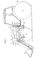
- Fig. 1 is a side elevation of a tractor having attached to it a front loader designed for drive-in attachment thereto;
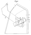
- Fig. 2 is a side elevation of the tractor with the detachable main portion of the loader removed, showing the loader attachment brackets permanently secured to the tractor;
- Fig. 3 is a side elevation of the detachable main portion of the loader standing alone;
- Fig. 4 is a side elevation on a larger scale of the upper part of a rear attachment bracket with an attachment pin clamped in operative position;
- Fig. 5 is a section on an intermediate scale on the line 5 - 5 in Fig. 4; and
- Fig. 6 is a side elevation corresponding to Fig. 4 with the pin unclamped for easy withdrawal.
- Referring now to Figs. 1 to 3 of the drawings, a front loader designed for drive-in attachment to a tractor includes a front attachment bracket indicated generally at 10 comprising two
side plates 11 interconnected near their upper ends by a transverse bar 12 and welded at their lower ends to a basically U-shaped ballast-weight carrier 13 the arms of which are adapted to he permanently secured by set-screws 14 near the front of thetractor frame 15 at each side thereof; and tworear attachment brackets 16 adapted to be permanently secured by set-screws 17 near the mid-point of the length of thetractor frame 15 at each side thereof. - A detachable main portion of the loader includes a sub-frame indicated generally at 18 adapted to he temporarily secured to the
brackets elongated side members 19 interconnected at their front ends by aradiator guard 20. A loader boom assembly indicated generally at 21 comprising twoparallel booms 22 of shallow inverted V-shape interconnected between their apices and front ends by twocross-members 23 and 24 has the rear ends of itsbooms 22 pivotably mounted about a commontransverse axis 25 on the upper ends ofrespective pedestals 26 secured by welding to the rear ends of theside members 19 of thesub-frame 18, and theboom assembly 21 is pivotable relative to thesub-frame 18 by two hydraulic piston-and-cylinder assemblies 27 each of which is pivotally connected between the lower end of one of thepedestals 26 and astiffening plate 28 welded to the apex of the associatedboom 22. Aloader bucket 29, or a similar tool such as a manure fork, is pivotably mounted about a commontransverse axis 30 on the front ends of thebooms 22, and is pivotable relative to theboom assembly 21 by two hydraulic piston-and-cylinder assemblies 31 each of which is pivotally connected between the rearmost cross-member 23 and a hole in alug 32 near one side of thebucket 29, thecommon axis 33 of the holes in thelugs 32 being spaced from but parallel to thepivot axis 30 of thebucket 29. Atelescopic strut 34 having afoot 57 is pivotably mounted on eachstiffening plate 28 so as to be moveable manually between a stowed retracted position (See Fig. 1) contiguous with the forward part of the associatedboom 22; a first deployed extended position (See Fig. 3) in which it is locked at an angle of, say, 40° to said part of said boom by a pivotableauxiliary strut 35 in order to support the rear end of the detachable main portion of the loader, when said portion is not in use, at the required height for drive-in attachment to the front andrear brackets bucket 29; and a second deployed extended position (not shown) in which it is secured alongside the associated hydraulic piston-and-cylinder assembly 27 with itsfoot 57 engaging in a recess at the lower front corner of the associatedpedestal 26 in order to lock theboom assembly 21 mechanically in its fully raised position whilst the detachable main portion of the loader is attached to the tractor. - The
sub-frame 18 locates on thefront bracket 10 by means of twohorizontal ribs 36 fixed to and projecting laterally outwards from therespective side plates 11 and each engageable between upper and lower forwardly convergingguides radiator guard 20, and also by means of twowedges 39 secured to and projecting laterally outwards from therespective side plates 11 and each engageable with one of two mutually forwardly convergingplates 40 secured to and projecting laterally inwards from the respective sides of theradiator guard 20. Either thewedges 39 or theplates 40 are made adjustable in a fore-and-aft direction. - Referring now to Figs. 4 to 6 of the drawings, the upper part of each
rear bracket 16 is substantially U-shaped in plan view, with arear wall 41 and two mainlyparallel side walls 42, and the lower rear corner of eachpedestal 26 of thesub-frame 18 is secured within the upper part of the associatedrear bracket 16 by an easy-release attachment pin 43 which passes with substantialradial clearance 44 through alignedholes 45 inside walls 42 of the upper part of thebracket 16. Thepin 43 has a hand-grip 46 welded to its end remote from the tractor and fits, between theholes 45, in aneccentric bush 47 which fits in aboss 48 fixed to the lower rear corner of thepedestal 26. Thebush 47 is readily rotateable manually, by means of ahandle 49 comprising a radial arm welded to its end remote from the tractor, into an operative position (See Figs. 4 and 5) in which thepin 43 establishes contact at the points indicated by thearrows 50 with the front sides of theholes 45 and theboss 48 establishes clamping contact at the points indicated by thearrows notch 53 in a cam-plate 54 welded to therear wall 41 of the upper part of thebracket 16, or into an easy-release position (See Fig. 6) in which said contacts are disestablished and thepin 43 can be freely withdrawn. When thebush 47 is in its operative position the arrangment is self-tightening, the weight and angular disposition of thehandle 49 ensuring that contact is constantly maintained at the points indicated by thearrows pin 43 and its associatedcomponents handle 49 moving thebush 47 angularly and thereby causing the points of contact indicated by thearrows 50 to be gradually relocated in an anti-clockwise direction as seen in Fig. 4. Thebush 47 is retained in theboss 48, to prevent its being dislodged whilst the main portion of the loader is not attached to the tractor, by acirclip 55 disposed at the opposite end of thebush 47 to thehandle 49 thereon. The pin is provided, near the opposite end to its hand-grip 46, with adiametrical hole 56 for the reception of a linch-pin (not shown) to retain thepin 43 in theholes 45.
Claims (9)
characterised in that each pin passes with substantial radial clearance through aligned axially-spaced holes in one rear bracket and fits, between said holes, in an eccentric bush which fits in a boss fixed to the sub-frame and is rotateable into an operative position in which the pin establishes contact with one side of said holes and the boss establishes c.ontact with a cam-plate fixed to the rear bracket, or into an easy release position in which said contacts are disestablished.
Applications Claiming Priority (2)
| Application Number | Priority Date | Filing Date | Title |
|---|---|---|---|
| GB8217601 | 1982-06-17 | ||
| GB8217601 | 1982-06-17 |
Publications (2)
| Publication Number | Publication Date |
|---|---|
| EP0097437A1 true EP0097437A1 (en) | 1984-01-04 |
| EP0097437B1 EP0097437B1 (en) | 1986-02-26 |
Family
ID=10531118
Family Applications (1)
| Application Number | Title | Priority Date | Filing Date |
|---|---|---|---|
| EP83303102A Expired EP0097437B1 (en) | 1982-06-17 | 1983-05-31 | Tractor front loader |
Country Status (3)
| Country | Link |
|---|---|
| US (1) | US4498839A (en) |
| EP (1) | EP0097437B1 (en) |
| DE (2) | DE3362272D1 (en) |
Cited By (2)
| Publication number | Priority date | Publication date | Assignee | Title |
|---|---|---|---|---|
| GB2344735A (en) * | 1998-12-18 | 2000-06-21 | Agco Gmbh & Co | Releasably securing a loader attachment on a vehicle |
| DE102016117241A1 (en) | 2016-09-14 | 2018-03-15 | Claas Tractor Sas | Agricultural vehicle |
Families Citing this family (10)
| Publication number | Priority date | Publication date | Assignee | Title |
|---|---|---|---|---|
| US5129780A (en) * | 1990-07-30 | 1992-07-14 | Du-Al Manufacturing Company | Hydra-lift stand for loaders |
| US5322579A (en) * | 1993-03-30 | 1994-06-21 | Illinois Tool Works Inc. | Method of forming side seams for zippered bags or packages |
| US5540289A (en) * | 1994-03-30 | 1996-07-30 | Kubota Corporation | Stand apparatus for use in coupling and uncoupling a front loader |
| US6446367B1 (en) * | 1999-03-24 | 2002-09-10 | Kubota Corporation | Tractor-loader-backhoe |
| US7134832B2 (en) * | 2004-08-27 | 2006-11-14 | Cnh America Llc | Method and apparatus for mounting a front loader to a tractor |
| US7530779B2 (en) * | 2007-09-28 | 2009-05-12 | Cnh America Llc | Cam-lock mechanism for attachment of implements to prime movers |
| USD595746S1 (en) * | 2008-09-19 | 2009-07-07 | Yanmar Co., Ltd. | Front loader |
| USD610172S1 (en) | 2009-06-22 | 2010-02-16 | Yanmar Co., Ltd. | Front loader |
| US8322969B1 (en) | 2009-09-10 | 2012-12-04 | Westendorf Manufacturing, Co. | Loader assembly and method providing for cantilevered storage of lift arms |
| US8544885B2 (en) * | 2009-12-10 | 2013-10-01 | Deere & Company | Folding parking stand |
Citations (6)
| Publication number | Priority date | Publication date | Assignee | Title |
|---|---|---|---|---|
| US3156367A (en) * | 1963-01-16 | 1964-11-10 | Int Harvester Co | Tractor mounted loader |
| GB1118996A (en) * | 1966-02-16 | 1968-07-03 | Int Harvester Co | Arrangement for mounting a loader on a vehicle |
| DE1531063A1 (en) * | 1967-06-09 | 1969-08-28 | Stoll Walter Dipl Ing | Tractor with front loader arm |
| FR2282561A1 (en) * | 1974-08-23 | 1976-03-19 | Midland Ind Computing | Loading shovel attachment for use on tractors - pivotted loading shovel frame pin jointed on tracor with dowel retaining mechanism (SW220376) |
| US4275984A (en) * | 1979-03-19 | 1981-06-30 | Farmhand, Inc. | Parking stand |
| FR2477362A1 (en) * | 1980-03-10 | 1981-09-11 | Granier Raymond | Tractor front loader rapid-attachment system - has spring-loaded bolts with flattened portions passing through slots |
Family Cites Families (4)
| Publication number | Priority date | Publication date | Assignee | Title |
|---|---|---|---|---|
| US4318662A (en) * | 1980-06-05 | 1982-03-09 | J. I. Case Company | Backhoe coupling device |
| US4345870A (en) * | 1980-06-16 | 1982-08-24 | Hesston Corporation | Quick attach loader |
| US4383793A (en) * | 1981-02-26 | 1983-05-17 | Chromalloy American Corporation | Tractor implement mount |
| US4420272A (en) * | 1982-09-27 | 1983-12-13 | Ingalls William E | Method and structure for bearing the eccentricity of a bushing bore |
-
1983
- 1983-05-31 EP EP83303102A patent/EP0097437B1/en not_active Expired
- 1983-05-31 DE DE8383303102T patent/DE3362272D1/en not_active Expired
- 1983-05-31 DE DE198383303102T patent/DE97437T1/en active Pending
- 1983-06-07 US US06/502,051 patent/US4498839A/en not_active Expired - Fee Related
Patent Citations (6)
| Publication number | Priority date | Publication date | Assignee | Title |
|---|---|---|---|---|
| US3156367A (en) * | 1963-01-16 | 1964-11-10 | Int Harvester Co | Tractor mounted loader |
| GB1118996A (en) * | 1966-02-16 | 1968-07-03 | Int Harvester Co | Arrangement for mounting a loader on a vehicle |
| DE1531063A1 (en) * | 1967-06-09 | 1969-08-28 | Stoll Walter Dipl Ing | Tractor with front loader arm |
| FR2282561A1 (en) * | 1974-08-23 | 1976-03-19 | Midland Ind Computing | Loading shovel attachment for use on tractors - pivotted loading shovel frame pin jointed on tracor with dowel retaining mechanism (SW220376) |
| US4275984A (en) * | 1979-03-19 | 1981-06-30 | Farmhand, Inc. | Parking stand |
| FR2477362A1 (en) * | 1980-03-10 | 1981-09-11 | Granier Raymond | Tractor front loader rapid-attachment system - has spring-loaded bolts with flattened portions passing through slots |
Cited By (5)
| Publication number | Priority date | Publication date | Assignee | Title |
|---|---|---|---|---|
| GB2344735A (en) * | 1998-12-18 | 2000-06-21 | Agco Gmbh & Co | Releasably securing a loader attachment on a vehicle |
| EP1010819A3 (en) * | 1998-12-18 | 2000-10-25 | Agco GmbH & Co. | Apparatus for detachably securing a loader attachment on a vehicle |
| GB2344735B (en) * | 1998-12-18 | 2003-06-25 | Agco Gmbh & Co | Apparatus for detachably securing a loader attachment on a vehicle |
| DE102016117241A1 (en) | 2016-09-14 | 2018-03-15 | Claas Tractor Sas | Agricultural vehicle |
| EP3296160A1 (en) | 2016-09-14 | 2018-03-21 | CLAAS Tractor S.A.S. | Agricultural vehicle |
Also Published As
| Publication number | Publication date |
|---|---|
| EP0097437B1 (en) | 1986-02-26 |
| DE3362272D1 (en) | 1986-04-03 |
| US4498839A (en) | 1985-02-12 |
| DE97437T1 (en) | 1984-08-16 |
Similar Documents
| Publication | Publication Date | Title |
|---|---|---|
| CA2197482C (en) | Parkable grapple having quick attachment to loader holder | |
| EP0097437B1 (en) | Tractor front loader | |
| EP0113177B1 (en) | Tractor front loader | |
| US3985249A (en) | Quick change attachment | |
| US6168369B1 (en) | Carrier retainer system | |
| US3665622A (en) | Converter bracket for a lift bucket | |
| EP0627033B1 (en) | Front end loader attachment convertible between loading bucket and side-shift-angle dozer configurations | |
| EP0091943B1 (en) | Releasable bucket for backhoe | |
| US4787811A (en) | Quick attach means for attachments | |
| US4606692A (en) | Quick-mount loader for articulated tractors | |
| EP0168597A1 (en) | Earth moving/loading implement | |
| US4030626A (en) | Clamp for scoop loader | |
| CA2126999C (en) | Structure for attaching a loader to a tractor | |
| EP0524490B1 (en) | Dredger | |
| US3977548A (en) | Cylinder attachment means for an excavator and method for using the same | |
| US4266906A (en) | Materials handling device and the method of mounting the same on a tractor | |
| US6487799B2 (en) | Removable hitch attachment for earth-moving equipment | |
| CA1308072C (en) | Loader mounting system | |
| US3912095A (en) | Heavy-duty loader for quick assembly on a tractor | |
| US4470751A (en) | Apparatus for attaching front loader to vehicle | |
| US3700131A (en) | Grab fork attachment for a loader bucket | |
| US4621973A (en) | Tractor loader having multi-adjustment mountings | |
| KR200488425Y1 (en) | Fork Lift Attachment for Excavators | |
| US3967397A (en) | Rake attachment for back hoe and the like | |
| US6604752B1 (en) | Front end hydraulic hitch attachment |
Legal Events
| Date | Code | Title | Description |
|---|---|---|---|
| PUAI | Public reference made under article 153(3) epc to a published international application that has entered the european phase |
Free format text: ORIGINAL CODE: 0009012 |
|
| AK | Designated contracting states |
Designated state(s): DE FR GB SE |
|
| EL | Fr: translation of claims filed | ||
| RAP1 | Party data changed (applicant data changed or rights of an application transferred) |
Owner name: CASE POCLAIN CORPORATION LIMITED |
|
| DET | De: translation of patent claims | ||
| 17P | Request for examination filed |
Effective date: 19840615 |
|
| GRAA | (expected) grant |
Free format text: ORIGINAL CODE: 0009210 |
|
| AK | Designated contracting states |
Designated state(s): DE FR GB SE |
|
| REF | Corresponds to: |
Ref document number: 3362272 Country of ref document: DE Date of ref document: 19860403 |
|
| RAP2 | Party data changed (patent owner data changed or rights of a patent transferred) |
Owner name: J.I. CASE EUROPE LIMITED |
|
| ET | Fr: translation filed | ||
| PLBE | No opposition filed within time limit |
Free format text: ORIGINAL CODE: 0009261 |
|
| STAA | Information on the status of an ep patent application or granted ep patent |
Free format text: STATUS: NO OPPOSITION FILED WITHIN TIME LIMIT |
|
| 26N | No opposition filed | ||
| PG25 | Lapsed in a contracting state [announced via postgrant information from national office to epo] |
Ref country code: GB Effective date: 19890531 |
|
| PG25 | Lapsed in a contracting state [announced via postgrant information from national office to epo] |
Ref country code: SE Effective date: 19890601 |
|
| GBPC | Gb: european patent ceased through non-payment of renewal fee | ||
| PG25 | Lapsed in a contracting state [announced via postgrant information from national office to epo] |
Ref country code: FR Free format text: LAPSE BECAUSE OF NON-PAYMENT OF DUE FEES Effective date: 19900131 |
|
| PG25 | Lapsed in a contracting state [announced via postgrant information from national office to epo] |
Ref country code: DE Effective date: 19900201 |
|
| REG | Reference to a national code |
Ref country code: FR Ref legal event code: ST |
|
| EUG | Se: european patent has lapsed |
Ref document number: 83303102.4 Effective date: 19900418 |