EP0096758B1 - Control system and method for a power delivery system having a continuously variable ratio transmission - Google Patents
Control system and method for a power delivery system having a continuously variable ratio transmission Download PDFInfo
- Publication number
- EP0096758B1 EP0096758B1 EP83104918A EP83104918A EP0096758B1 EP 0096758 B1 EP0096758 B1 EP 0096758B1 EP 83104918 A EP83104918 A EP 83104918A EP 83104918 A EP83104918 A EP 83104918A EP 0096758 B1 EP0096758 B1 EP 0096758B1
- Authority
- EP
- European Patent Office
- Prior art keywords
- prime mover
- engine
- fuel
- control system
- continuously variable
- Prior art date
- Legal status (The legal status is an assumption and is not a legal conclusion. Google has not performed a legal analysis and makes no representation as to the accuracy of the status listed.)
- Expired
Links
- 230000005540 biological transmission Effects 0.000 title claims description 28
- 238000000034 method Methods 0.000 title claims description 11
- 239000000446 fuel Substances 0.000 claims description 45
- 238000002485 combustion reaction Methods 0.000 claims description 3
- MROJXXOCABQVEF-UHFFFAOYSA-N Actarit Chemical compound CC(=O)NC1=CC=C(CC(O)=O)C=C1 MROJXXOCABQVEF-UHFFFAOYSA-N 0.000 claims 8
- 230000001419 dependent effect Effects 0.000 claims 2
- 230000008859 change Effects 0.000 description 9
- 230000001052 transient effect Effects 0.000 description 3
- 238000010586 diagram Methods 0.000 description 2
- 238000006073 displacement reaction Methods 0.000 description 2
- 230000001133 acceleration Effects 0.000 description 1
- 238000004458 analytical method Methods 0.000 description 1
- 238000013459 approach Methods 0.000 description 1
- 230000008878 coupling Effects 0.000 description 1
- 238000010168 coupling process Methods 0.000 description 1
- 238000005859 coupling reaction Methods 0.000 description 1
- 230000000694 effects Effects 0.000 description 1
- 239000012530 fluid Substances 0.000 description 1
- 230000002706 hydrostatic effect Effects 0.000 description 1
- 238000002347 injection Methods 0.000 description 1
- 239000007924 injection Substances 0.000 description 1
- 230000007246 mechanism Effects 0.000 description 1
- 238000012986 modification Methods 0.000 description 1
- 230000004048 modification Effects 0.000 description 1
- 230000001141 propulsive effect Effects 0.000 description 1
- 230000004044 response Effects 0.000 description 1
- 238000005096 rolling process Methods 0.000 description 1
- 239000007787 solid Substances 0.000 description 1
Images

Classifications
-
- B—PERFORMING OPERATIONS; TRANSPORTING
- B60—VEHICLES IN GENERAL
- B60W—CONJOINT CONTROL OF VEHICLE SUB-UNITS OF DIFFERENT TYPE OR DIFFERENT FUNCTION; CONTROL SYSTEMS SPECIALLY ADAPTED FOR HYBRID VEHICLES; ROAD VEHICLE DRIVE CONTROL SYSTEMS FOR PURPOSES NOT RELATED TO THE CONTROL OF A PARTICULAR SUB-UNIT
- B60W10/00—Conjoint control of vehicle sub-units of different type or different function
- B60W10/04—Conjoint control of vehicle sub-units of different type or different function including control of propulsion units
- B60W10/06—Conjoint control of vehicle sub-units of different type or different function including control of propulsion units including control of combustion engines
-
- B—PERFORMING OPERATIONS; TRANSPORTING
- B60—VEHICLES IN GENERAL
- B60W—CONJOINT CONTROL OF VEHICLE SUB-UNITS OF DIFFERENT TYPE OR DIFFERENT FUNCTION; CONTROL SYSTEMS SPECIALLY ADAPTED FOR HYBRID VEHICLES; ROAD VEHICLE DRIVE CONTROL SYSTEMS FOR PURPOSES NOT RELATED TO THE CONTROL OF A PARTICULAR SUB-UNIT
- B60W10/00—Conjoint control of vehicle sub-units of different type or different function
- B60W10/04—Conjoint control of vehicle sub-units of different type or different function including control of propulsion units
-
- B—PERFORMING OPERATIONS; TRANSPORTING
- B60—VEHICLES IN GENERAL
- B60W—CONJOINT CONTROL OF VEHICLE SUB-UNITS OF DIFFERENT TYPE OR DIFFERENT FUNCTION; CONTROL SYSTEMS SPECIALLY ADAPTED FOR HYBRID VEHICLES; ROAD VEHICLE DRIVE CONTROL SYSTEMS FOR PURPOSES NOT RELATED TO THE CONTROL OF A PARTICULAR SUB-UNIT
- B60W10/00—Conjoint control of vehicle sub-units of different type or different function
- B60W10/10—Conjoint control of vehicle sub-units of different type or different function including control of change-speed gearings
- B60W10/101—Infinitely variable gearings
-
- B—PERFORMING OPERATIONS; TRANSPORTING
- B60—VEHICLES IN GENERAL
- B60W—CONJOINT CONTROL OF VEHICLE SUB-UNITS OF DIFFERENT TYPE OR DIFFERENT FUNCTION; CONTROL SYSTEMS SPECIALLY ADAPTED FOR HYBRID VEHICLES; ROAD VEHICLE DRIVE CONTROL SYSTEMS FOR PURPOSES NOT RELATED TO THE CONTROL OF A PARTICULAR SUB-UNIT
- B60W10/00—Conjoint control of vehicle sub-units of different type or different function
- B60W10/10—Conjoint control of vehicle sub-units of different type or different function including control of change-speed gearings
- B60W10/101—Infinitely variable gearings
- B60W10/107—Infinitely variable gearings with endless flexible members
-
- B—PERFORMING OPERATIONS; TRANSPORTING
- B60—VEHICLES IN GENERAL
- B60W—CONJOINT CONTROL OF VEHICLE SUB-UNITS OF DIFFERENT TYPE OR DIFFERENT FUNCTION; CONTROL SYSTEMS SPECIALLY ADAPTED FOR HYBRID VEHICLES; ROAD VEHICLE DRIVE CONTROL SYSTEMS FOR PURPOSES NOT RELATED TO THE CONTROL OF A PARTICULAR SUB-UNIT
- B60W30/00—Purposes of road vehicle drive control systems not related to the control of a particular sub-unit, e.g. of systems using conjoint control of vehicle sub-units
- B60W30/18—Propelling the vehicle
- B60W30/1819—Propulsion control with control means using analogue circuits, relays or mechanical links
-
- B—PERFORMING OPERATIONS; TRANSPORTING
- B60—VEHICLES IN GENERAL
- B60W—CONJOINT CONTROL OF VEHICLE SUB-UNITS OF DIFFERENT TYPE OR DIFFERENT FUNCTION; CONTROL SYSTEMS SPECIALLY ADAPTED FOR HYBRID VEHICLES; ROAD VEHICLE DRIVE CONTROL SYSTEMS FOR PURPOSES NOT RELATED TO THE CONTROL OF A PARTICULAR SUB-UNIT
- B60W30/00—Purposes of road vehicle drive control systems not related to the control of a particular sub-unit, e.g. of systems using conjoint control of vehicle sub-units
- B60W30/18—Propelling the vehicle
- B60W30/188—Controlling power parameters of the driveline, e.g. determining the required power
- B60W30/1882—Controlling power parameters of the driveline, e.g. determining the required power characterised by the working point of the engine, e.g. by using engine output chart
-
- F—MECHANICAL ENGINEERING; LIGHTING; HEATING; WEAPONS; BLASTING
- F16—ENGINEERING ELEMENTS AND UNITS; GENERAL MEASURES FOR PRODUCING AND MAINTAINING EFFECTIVE FUNCTIONING OF MACHINES OR INSTALLATIONS; THERMAL INSULATION IN GENERAL
- F16H—GEARING
- F16H61/00—Control functions within control units of change-speed- or reversing-gearings for conveying rotary motion ; Control of exclusively fluid gearing, friction gearing, gearings with endless flexible members or other particular types of gearing
- F16H61/66—Control functions within control units of change-speed- or reversing-gearings for conveying rotary motion ; Control of exclusively fluid gearing, friction gearing, gearings with endless flexible members or other particular types of gearing specially adapted for continuously variable gearings
- F16H61/662—Control functions within control units of change-speed- or reversing-gearings for conveying rotary motion ; Control of exclusively fluid gearing, friction gearing, gearings with endless flexible members or other particular types of gearing specially adapted for continuously variable gearings with endless flexible members
- F16H61/66254—Control functions within control units of change-speed- or reversing-gearings for conveying rotary motion ; Control of exclusively fluid gearing, friction gearing, gearings with endless flexible members or other particular types of gearing specially adapted for continuously variable gearings with endless flexible members controlling of shifting being influenced by a signal derived from the engine and the main coupling
Definitions
- This invention relates to a control method and a control system according to the pre-characterizing portion of claim 1 respectively claim 6.
- CVT Continuously variable ratio transmissions
- CVT configurations have been developed in the prior art. These include, for example, hydrostatic transmissions; rolling contact traction drives; overrunning clutch designs; electrics; multi-speed gear boxes with slipping clutch; and V-belt traction drives. Of these the V-belt traction drives appear attractive for small to medium size passenger car applications because of their compactness, lightness and simplicity of design.
- this type of CVT comprises a V-belt which interconnects a driver sheave and driven sheave, the diameters of the sheaves being variable to change the ratio of the CVT.
- Recent advances in belt design have resulted in improved belt durability and longevity. If sheave movement can be properly controlled so as to avoid undue stresses on the belt, it is expected that a very long belt life can be achieved.
- Figure 1 is a typical performance map of a four cylinder spark ignition passenger car engine having a displacement of approximately 2.5 liters.
- the map is a plot of engine torque T E and brake horsepower BHP as a function of engine speed N E .
- the dot-dash line near the top of the map is a plat of engine torque at full throttle.
- the series of curves in solid black lines are fuel consumption contours, indicating constant brake specific fuel consumption (BSFC) in Ibs.. M/BHP/HR (1 Ib.è0,45359 kg.). Minimum fuel consumption occurs at a point designed by 0.4 pounds per horsepower-hour.
- the series of dashed lines indicates power output of the engine.
- the ideal operating line for low fuel consumption is indicated by the heavy solid line f/N E ); this curve being a function of engine speed.
- the ideal operating line for low fuel consumption is purely a function of engine characteristics and is optimal regardless of vehicle road speed.
- Other ideal operating lines may appear on the performance map, for example, the ideal operating line for low emissions.
- forward speed ratios usually are available in only four or five steps.
- the operating point of the engine on the performance map is determined by drive shaft speed, power or torque commanded, and transmission gear ratio. Since there are only a few gear ratios available in a typical transmission, the engine must be throttled much of the time. The engine must therefore operate most of the time at high BSFC values.
- a CVT is able to vary its speed ratio continuously to allow the engine to run at wider throttle and lower BSFC values.
- FIG. 2 schematically illustrates a system described in greater detail in U.S. Patent No. 4,152,947.
- engine speed and' throttle position control the ratio of the CVT.
- The' throttle is under the direct control of the vehicle accelerator pedal.
- the CVT disclosed in this patent is the V-belt traction type.
- FIG. 3 is a schematic representation of the system described in greater detail in U.S. Patent No. 4,091,690.
- engine throttle is likewise primarily a function of commanded power or torque by direct connection with the accelerator pedal.
- the computer generates a ratio rate signal to change the CVT ratio as a function of measured throttle position, and engine torque and speed. Inherently sensed output torque also affects the CVT ratio.
- throttle position is controlled directly by the vehicle accelerator peda, or is a direct function of pedal position, as well as other parameters.
- Engine and transmission control usually are directly related to one another. Such control schemes permit engine operation during transients to vary from the ideal operating line. Excursions away from the ideal operating line result in less than optimum engine operation (e.g., excessive fuel consumption, or excessive emissions), until effective control is resumed by the system during steady state operation. As pointed out earlier, however, most vehicular operation is transient in nature, rather than steady state, so that substantially all engine operation occurs off the target operating line. Emissions calibrations must therefore be made in a substantial portion of the engine performance map. Most prior art control systems also must be specifically tailored to particular engines. This requires numerous specially designed control systems for a fleet of differently powered vehicles.
- DE-A-28 11 574 discloses a control method and system, wherein by way of a command means a desired system performance is given, for which an assigned transmission adjustment is selected in dependence on characteristic diagram stored in a transmission data field storage.
- the characteristic diagram determines the respective transmission ratio in dependence on the desired system performance and the vehicle speed.
- the throttle position is determined in dependence on the desired system performance and the engine speed.
- a transmission ratio of the ratio transmission is predetermined as a target value. Furthermore permanent standardization of the power values is carried out.
- the subject matter of the invention is to further develop the last mentioned control method and system in such a way that maintaining the engine operation on the ideal operating line is simplified.
- the characteristics of the control scheme should remain the same irrespective of the type of engine which is coupled to the CVT.
- the drive ratio of the transmission varies as a function of required power or torque to thereby cause the speed of the prime mover to vary.
- the predetermined fuel function defining the desired fuel requirement for the prime mover in relation to the speed of the prime mover fuel delivery to the prime mover is determined by the speed of the prime mover.
- the invention is described throughout this specification in the context of an engine-CVT propulsion system for an automotive vehicle. It is to be understood, however, that the principles of the invention are equally applicable to any type of power delivery system, including but not limited to other vehicular systems using internal or external combustion engines of any design, or to stationary power plants for driving compressors, generators or any other type of machinery.
- throttle the term is understood to encompass any mechanism for controlling the delivery of fuel to the engine or other prime mover, be it a conventional carburetted spark-ignition engine wherein fuel flow varies with throttle butterfly position, a fuel injected spark-ignition or diesel engine, a gas turbine, and so on.
- a prime mover or engine 100 of an automotive vehicle is coupled to a continuously variable drive ratio transmission (CVT) 200 through a clutch or fluid coupling (not shown).
- Fuel is fed to the engine 100 by a fuel delivery means 102, which may be throttle and fuel jets of a conventional carburettor, a fuel injection system or the like.
- CVT 200 is illustrated as a V-belt traction drive type, having a V-belt which drivingly engages a variable diameter driver sheave 204 and variable diameter driven sheave 206.
- the driver sheave 204 has an axially fixed portion 208 and an axially movable portion 210.
- Axial movement of the portion 210 toward or away from the portion 208 will effect a change in driving diameter of the driver sheave 204.
- the driven sheave 206 has an axially fixed portion 212 and an axially movable portion 214, axial movement of the portion 214 effecting a change in driving ratio of the driven sheave 206.
- An output shaft 108 delivers power and torque from the engine 100 and the CVT 200 to the driving wheels of the vehicle.
- the axial position of the movable portion 214 of the driven sheave 206 is determined by the position a of a command means or vehicle accelerator pedal 104.
- the axial position of the movable portion 210 of the driver sheave 204 is determined by the difference between load torque, as seen by the driver sheave 204, and engine output torque through a conventional spring-loaded torque ramp 106.
- CVT ratio is, therefore, strictly a function of desired power delivery system performance or commanded power or torque as commanded by the accelerator pedal 104, and the load fed back through the CVT 200 to the torque ramp 106.
- Engine control is independently provided by an engine controller 110 which adjusts the fuel delivery means 102 only in accordance with measured engine speed N e .
- This relationship may desirably be the ideal engine operating line for low fuel consumption, the ideal operating line for low emissions, a compromise of the two or any other desired engine operating characteristic.
- control scheme quite simply and effectively accompishes its primary objective of maintaining engine operation along an ideal operating line.
- a change of accelerator pedal position causes a change of ratio of the CVT. This causes a change in the load on the engine, which results in an engine speed change.
- Fuel delivery is then precisely adjusted in accordance with the ideal operating line to precisely match the fuel requirements of the engine for the load placed thereon.
- Transmission control requires only load and accelerator pedal position sensing, while engine control requires only engine speed sensing.
- the control scheme can be accomplished by the use of electronic and/or mechanical components, it being understood that any type of control system which functions in the manner described may be used.
Landscapes
- Engineering & Computer Science (AREA)
- Chemical & Material Sciences (AREA)
- Combustion & Propulsion (AREA)
- Mechanical Engineering (AREA)
- Transportation (AREA)
- General Engineering & Computer Science (AREA)
- Automation & Control Theory (AREA)
- Control Of Driving Devices And Active Controlling Of Vehicle (AREA)
- Control Of Transmission Device (AREA)
- Output Control And Ontrol Of Special Type Engine (AREA)
- Combined Controls Of Internal Combustion Engines (AREA)
Description
- This invention relates to a control method and a control system according to the pre-characterizing portion of
claim 1 respectively claim 6. - The quest for greater fuel economy of automotive vehicles has led to significant improvements in engine and transmission design and control. Continuously variable ratio transmissions (CVT) have shown particular promise in this regard. It will be appreciated that at any given vehicle speed, and for any needed propulsive force, a certain transmission ratio will provide maximum fuel economy for a given engine. In addition, for any given vehicle speed, one transmission ratio will permit maximum acceleration with that engine. Since a CVT with the proper ratio range can provide any desired transmission ratio, it is obviously attractive for automobiles from the standpoint of economy, low emissions and performance. If the mechanical efficiency of the CVT is high and its ratio range is wide enough, it can even be possible to have both maximum economy and maximum performance in the same vehicle. Among the obvious benefits are fully automatic operation, smooth, stepless and rapid response to driver demand, and quieter cruising.
- Many different CVT configurations have been developed in the prior art. These include, for example, hydrostatic transmissions; rolling contact traction drives; overrunning clutch designs; electrics; multi-speed gear boxes with slipping clutch; and V-belt traction drives. Of these the V-belt traction drives appear attractive for small to medium size passenger car applications because of their compactness, lightness and simplicity of design. Basically, this type of CVT comprises a V-belt which interconnects a driver sheave and driven sheave, the diameters of the sheaves being variable to change the ratio of the CVT. Recent advances in belt design have resulted in improved belt durability and longevity. If sheave movement can be properly controlled so as to avoid undue stresses on the belt, it is expected that a very long belt life can be achieved.
- Many control schemes have been devised for engine-CVT systems in attempts to maximize fuel economy. These have been based on empirical analyses of individual engine performance, and the realization that, for any desired power output, there is an optimum combination of engine speed and torque which will result in minimum fuel consumption. This is illustrated in Figure 1.
- Figure 1 is a typical performance map of a four cylinder spark ignition passenger car engine having a displacement of approximately 2.5 liters. The map is a plot of engine torque TE and brake horsepower BHP as a function of engine speed NE. The dot-dash line near the top of the map is a plat of engine torque at full throttle. The series of curves in solid black lines are fuel consumption contours, indicating constant brake specific fuel consumption (BSFC) in Ibs.. M/BHP/HR (1 Ib.è0,45359 kg.). Minimum fuel consumption occurs at a point designed by 0.4 pounds per horsepower-hour. The series of dashed lines indicates power output of the engine. The ideal operating line for low fuel consumption is indicated by the heavy solid line f/NE); this curve being a function of engine speed. The ideal operating line for low fuel consumption is purely a function of engine characteristics and is optimal regardless of vehicle road speed. Other ideal operating lines may appear on the performance map, for example, the ideal operating line for low emissions. In a vehicle with a conventional, manually shifted gearbox, forward speed ratios usually are available in only four or five steps. The operating point of the engine on the performance map is determined by drive shaft speed, power or torque commanded, and transmission gear ratio. Since there are only a few gear ratios available in a typical transmission, the engine must be throttled much of the time. The engine must therefore operate most of the time at high BSFC values. In contrast, a CVT is able to vary its speed ratio continuously to allow the engine to run at wider throttle and lower BSFC values.
- Perhaps the most difficult task demanded of a control system for an engine-CVT system is to maintain engine operation along the ideal operating line. This is due to the almost continuous transient nature of operation of an automotive vehicle, there being hardly ever a time when road load and commanded torque or power remain constant. Transient conditions usually are dealt with by a change in CVT ratio, engine speed and throttle. Prior art control systems, by their very nature, permit an excursion of engine operation away from the ideal operating line before returning back to it at steady state. An example of such an excursion is shown in Figure as dashed line X-Y-Z. The result is than engine operation approaches, but hardly ever is maintained on the ideal operating line. Two such prior art systems are illustrated in Figures 2 and 3.
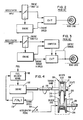
- Figure 2 schematically illustrates a system described in greater detail in U.S. Patent No. 4,152,947. In this system, engine speed and' throttle position control the ratio of the CVT. The' throttle is under the direct control of the vehicle accelerator pedal. The CVT disclosed in this patent is the V-belt traction type.
- Figure 3 is a schematic representation of the system described in greater detail in U.S. Patent No. 4,091,690. Here engine throttle is likewise primarily a function of commanded power or torque by direct connection with the accelerator pedal. The computer generates a ratio rate signal to change the CVT ratio as a function of measured throttle position, and engine torque and speed. Inherently sensed output torque also affects the CVT ratio.
- In these, as well as in virtually all other engine-CVT control systems, throttle position is controlled directly by the vehicle accelerator peda, or is a direct function of pedal position, as well as other parameters. Engine and transmission control usually are directly related to one another. Such control schemes permit engine operation during transients to vary from the ideal operating line. Excursions away from the ideal operating line result in less than optimum engine operation (e.g., excessive fuel consumption, or excessive emissions), until effective control is resumed by the system during steady state operation. As pointed out earlier, however, most vehicular operation is transient in nature, rather than steady state, so that substantially all engine operation occurs off the target operating line. Emissions calibrations must therefore be made in a substantial portion of the engine performance map. Most prior art control systems also must be specifically tailored to particular engines. This requires numerous specially designed control systems for a fleet of differently powered vehicles.
- DE-A-28 11 574 discloses a control method and system, wherein by way of a command means a desired system performance is given, for which an assigned transmission adjustment is selected in dependence on characteristic diagram stored in a transmission data field storage. The characteristic diagram determines the respective transmission ratio in dependence on the desired system performance and the vehicle speed. The throttle position is determined in dependence on the desired system performance and the engine speed. This is to say that the desired power delivery system performance required from the command means has an immediate and direct influence on both the controlling of the prime mover via the fuel delivery means and the controlling of the transmission. For both controlling operations the desired system performance is a base value.
- In this known method and system a transmission ratio of the ratio transmission is predetermined as a target value. Furthermore permanent standardization of the power values is carried out.
- The subject matter of the invention is to further develop the last mentioned control method and system in such a way that maintaining the engine operation on the ideal operating line is simplified. The characteristics of the control scheme should remain the same irrespective of the type of engine which is coupled to the CVT.
- This problem is according to the invention solved by the features contained in the characterizing portion of
claim 1 respectively claim 6. The drive ratio of the transmission varies as a function of required power or torque to thereby cause the speed of the prime mover to vary. According to the predetermined fuel function defining the desired fuel requirement for the prime mover in relation to the speed of the prime mover fuel delivery to the prime mover is determined by the speed of the prime mover. - Surprisingly it has been found that engine operation can readily be maintained along the ideal operating line by providing for totally independent engine and transmission control. That is, the position of the engine throttle is totally independent of accelerator pedal position. Throttle position and, hence, engine output torque simply is a function of engine speed only, and that function may be any desired relationship, for example, the ideal operating line for minimum fuel consumption, the ideal operating line for low emissions, or a compromise ideal operating line for low fuel consumption and low emissions. Torque or power commanded by the accelerator pedal controls CVT ratio, and engine speed is determined by the load placed thereon, which is a function of road load and CVT ratio. Hence, throttle position is precisely adjusted in accordance with the target function for any load placed on the engine.
- For convenience, the invention is described throughout this specification in the context of an engine-CVT propulsion system for an automotive vehicle. It is to be understood, however, that the principles of the invention are equally applicable to any type of power delivery system, including but not limited to other vehicular systems using internal or external combustion engines of any design, or to stationary power plants for driving compressors, generators or any other type of machinery. Where the term "throttle" is used, the term is understood to encompass any mechanism for controlling the delivery of fuel to the engine or other prime mover, be it a conventional carburetted spark-ignition engine wherein fuel flow varies with throttle butterfly position, a fuel injected spark-ignition or diesel engine, a gas turbine, and so on.
- Advantageous modifications of the inventional control method and the inventional control system derive from the subclaims.
- The invention is explained in the following detailed description, as set forth in the accompanying drawings, in which:
- Fig. 1 is the performance map of a typical four cylinder passenger car engine having a displacement of approximately 2.5 litres.
- Figs. 2 and 3 illustrate two forms of prior art engine-CVT control schemes; and
- Fig. 4 is a schematic illustration showing the functional relationship of the components of an engine-CVT control scheme according to the invention.
- Referring to Figure 4, a prime mover or
engine 100 of an automotive vehicle is coupled to a continuously variable drive ratio transmission (CVT) 200 through a clutch or fluid coupling (not shown). Fuel is fed to theengine 100 by a fuel delivery means 102, which may be throttle and fuel jets of a conventional carburettor, a fuel injection system or the like.CVT 200 is illustrated as a V-belt traction drive type, having a V-belt which drivingly engages a variablediameter driver sheave 204 and variable diameter drivensheave 206. Thedriver sheave 204 has an axially fixedportion 208 and an axiallymovable portion 210. Axial movement of theportion 210 toward or away from theportion 208 will effect a change in driving diameter of thedriver sheave 204. Similarly, the drivensheave 206 has an axially fixedportion 212 and an axiallymovable portion 214, axial movement of theportion 214 effecting a change in driving ratio of the drivensheave 206. Anoutput shaft 108 delivers power and torque from theengine 100 and theCVT 200 to the driving wheels of the vehicle. - The axial position of the
movable portion 214 of the drivensheave 206 is determined by the position a of a command means orvehicle accelerator pedal 104. The axial position of themovable portion 210 of thedriver sheave 204 is determined by the difference between load torque, as seen by thedriver sheave 204, and engine output torque through a conventional spring-loadedtorque ramp 106. - CVT ratio is, therefore, strictly a function of desired power delivery system performance or commanded power or torque as commanded by the
accelerator pedal 104, and the load fed back through theCVT 200 to thetorque ramp 106. Engine control, on the other hand, is independently provided by anengine controller 110 which adjusts the fuel delivery means 102 only in accordance with measured engine speed Ne. This relationship may desirably be the ideal engine operating line for low fuel consumption, the ideal operating line for low emissions, a compromise of the two or any other desired engine operating characteristic. - The above-described control scheme quite simply and effectively accompishes its primary objective of maintaining engine operation along an ideal operating line. A change of accelerator pedal position causes a change of ratio of the CVT. This causes a change in the load on the engine, which results in an engine speed change. Fuel delivery is then precisely adjusted in accordance with the ideal operating line to precisely match the fuel requirements of the engine for the load placed thereon. Transmission control requires only load and accelerator pedal position sensing, while engine control requires only engine speed sensing. The control scheme can be accomplished by the use of electronic and/or mechanical components, it being understood that any type of control system which functions in the manner described may be used.
Claims (10)
Applications Claiming Priority (2)
| Application Number | Priority Date | Filing Date | Title |
|---|---|---|---|
| US380921 | 1982-05-21 | ||
| US06/380,921 US4458561A (en) | 1982-05-21 | 1982-05-21 | Control system and method for a power delivery system having a continuously variable ratio transmission |
Publications (3)
| Publication Number | Publication Date |
|---|---|
| EP0096758A2 EP0096758A2 (en) | 1983-12-28 |
| EP0096758A3 EP0096758A3 (en) | 1985-07-24 |
| EP0096758B1 true EP0096758B1 (en) | 1989-04-26 |
Family
ID=23502974
Family Applications (1)
| Application Number | Title | Priority Date | Filing Date |
|---|---|---|---|
| EP83104918A Expired EP0096758B1 (en) | 1982-05-21 | 1983-05-18 | Control system and method for a power delivery system having a continuously variable ratio transmission |
Country Status (4)
| Country | Link |
|---|---|
| US (1) | US4458561A (en) |
| EP (1) | EP0096758B1 (en) |
| JP (1) | JPS5932642A (en) |
| DE (1) | DE3379722D1 (en) |
Families Citing this family (24)
| Publication number | Priority date | Publication date | Assignee | Title |
|---|---|---|---|---|
| US4515041A (en) * | 1980-05-21 | 1985-05-07 | Aisin Seiki Kabushiki Kaisha | Control system and method for a power delivery system having a continuously variable ratio transmission |
| EP0092228B1 (en) * | 1982-04-19 | 1988-01-20 | Nissan Motor Co., Ltd. | Method and apparatus for controlling reduction ratio of continuously variable transmission |
| JPS5926657A (en) * | 1982-08-04 | 1984-02-10 | Toyota Motor Corp | Control apparatus for vehicle equipped with stepless transmission type power transmitting mechanism |
| US4771656A (en) * | 1982-11-29 | 1988-09-20 | Toyota Jidoshi Kabushiki Kaisha | Cruise control method and apparatus for a vehicle with a continuously variable transmission |
| JPS59190554A (en) * | 1983-04-11 | 1984-10-29 | Mazda Motor Corp | Drive control device for automobile |
| JPS59187145A (en) * | 1983-03-26 | 1984-10-24 | Mazda Motor Corp | Drive control device for automobile |
| JPH066977B2 (en) * | 1983-05-09 | 1994-01-26 | トヨタ自動車株式会社 | Control device for continuously variable transmission for vehicle |
| JPH073261B2 (en) * | 1983-05-27 | 1995-01-18 | 日産自動車株式会社 | Controller for continuously variable transmission |
| JPH066979B2 (en) * | 1983-08-22 | 1994-01-26 | トヨタ自動車株式会社 | Control device for continuously variable transmission for vehicle |
| JPH066976B2 (en) * | 1983-08-29 | 1994-01-26 | トヨタ自動車株式会社 | Hydraulic control system for belt type continuously variable transmission |
| JPH07113402B2 (en) * | 1983-09-30 | 1995-12-06 | アイシン精機株式会社 | Drive system device using continuously variable transmission |
| JP2506630B2 (en) * | 1984-09-13 | 1996-06-12 | アイシン精機株式会社 | CVT control method |
| JPH0623019B2 (en) * | 1984-10-29 | 1994-03-30 | 株式会社島津製作所 | Vehicle acceleration control device |
| US4700590A (en) * | 1985-09-30 | 1987-10-20 | Aisin Seiki Kabushiki Kaisha | System for utilizing the negative torque of a power delivery system having a continuously variable ratio transmission for braking |
| US4699025A (en) * | 1985-09-30 | 1987-10-13 | Aisin Seiki Kabushiki Kaisha | Method and apparatus for controlling a power delivery system having a continuously variable ratio transmission |
| US4893526A (en) * | 1986-09-19 | 1990-01-16 | Toyota Jidosha Kabushiki Kaisha | Continuous variable transmission control system |
| US4897942A (en) * | 1988-10-14 | 1990-02-06 | Simplicity Manufacturing, Inc. | High efficiency snowthrower |
| JP2692254B2 (en) * | 1989-04-21 | 1997-12-17 | 日産自動車株式会社 | Transmission control device for continuously variable transmission |
| US5846157A (en) * | 1996-10-25 | 1998-12-08 | General Motors Corporation | Integrated control of a lean burn engine and a continuously variable transmission |
| DE60041546D1 (en) * | 2000-12-28 | 2009-03-26 | Renesas Tech Corp | PLL circuit with reduced settling time |
| SE520475C2 (en) * | 2001-11-19 | 2003-07-15 | Volvo Aero Corp | The gas turbine unit |
| US7824308B2 (en) * | 2007-09-06 | 2010-11-02 | Eaton Corporation | Methods for shifting a vehicle transmission |
| US7789795B2 (en) * | 2007-10-17 | 2010-09-07 | Eaton Corporation | Method for controlling a vehicle powertrain having step ratio gearing and a continuously variable transmission to achieve optimum engine fuel economy |
| US9752500B2 (en) * | 2013-03-14 | 2017-09-05 | Pratt & Whitney Canada Corp. | Gas turbine engine with transmission and method of adjusting rotational speed |
Family Cites Families (28)
| Publication number | Priority date | Publication date | Assignee | Title |
|---|---|---|---|---|
| US24347A (en) * | 1859-06-07 | Washing-machine | ||
| USRE24347E (en) | 1957-08-20 | Automatic variable pitch pulley | ||
| US2131157A (en) * | 1931-03-09 | 1938-09-27 | Gen Motors Corp | Control for variable speed power transmissions |
| US2059591A (en) * | 1934-07-11 | 1936-11-03 | Leoni Pilade | Automatic variable gear ratio transmission |
| US3044316A (en) * | 1955-01-07 | 1962-07-17 | Lloyd M Forster | Continuously variable transmission and automatic control |
| FR1182150A (en) * | 1957-09-09 | 1959-06-23 | Automatic gear transmission device, more particularly for motor vehicles | |
| US3008341A (en) * | 1959-07-06 | 1961-11-14 | Marvin E Cobb | Transmission mechanism |
| GB1035822A (en) * | 1963-01-11 | 1966-07-13 | Dowty Hydraulic Units Ltd | Infinitely variable transmission |
| US3368426A (en) * | 1965-03-12 | 1968-02-13 | Reimers Getriebe A G | Control mechanism for engine combined with infinitely variable transmission |
| US3552232A (en) * | 1966-09-26 | 1971-01-05 | Deere & Co | Transmission control |
| US3616706A (en) * | 1968-05-18 | 1971-11-02 | Yamaha Motor Co Ltd | Transmission device of a sheave drive type |
| FR2188688A5 (en) * | 1972-06-02 | 1974-01-18 | Peugeot & Renault | |
| GB1412557A (en) * | 1972-08-23 | 1975-11-05 | Elektr Strassenverkehr Ges | Electrically propelled vehicles |
| US4023442A (en) * | 1973-08-16 | 1977-05-17 | Oklahoma State University | Automatic control means for infinitely variable transmission |
| US4008567A (en) * | 1975-04-28 | 1977-02-22 | Joseph Hirsch | Torque control system |
| GB1525861A (en) * | 1975-10-23 | 1978-09-20 | Mullard Ltd | Vehicle power transmission arrangements and electronic control means therefor |
| NL165821C (en) * | 1976-02-09 | 1981-05-15 | Doornes Transmissie Bv | INFLATABLE VARIABLE TRANSMISSION. |
| DE2642738C2 (en) * | 1976-09-23 | 1986-08-07 | Robert Bosch Gmbh, 7000 Stuttgart | Method for regulating the operating behavior of an internal combustion engine in a specified operating range |
| US4091690A (en) * | 1976-09-28 | 1978-05-30 | Aisin Seiki Kabushiki Kaisha | Method for controlling continuously variable drive ratio transmissions and a system therefor |
| NL181597C (en) * | 1976-10-05 | 1987-09-16 | Volvo Car Bv | CONTINUOUSLY VARIABLE TRANSMISSION. |
| JPS5472359A (en) * | 1977-11-21 | 1979-06-09 | Aisin Seiki Co Ltd | Speed ratio control system for stageless speed change gear in vehicle |
| IE46274B1 (en) * | 1977-12-12 | 1983-04-20 | Kiely Denis Martin | A variable speed drive for a battery-powered electric vehicle |
| DE2811574A1 (en) * | 1978-03-17 | 1979-09-27 | Bosch Gmbh Robert | DEVICE FOR THE CONTROL OF A DRIVE MOTOR-GEAR UNIT OF A MOTOR VEHICLE |
| US4232572A (en) * | 1978-07-17 | 1980-11-11 | Sundstrand Corporation | Engine-transmission control system |
| DE2843256A1 (en) * | 1978-10-04 | 1980-04-17 | Bosch Gmbh Robert | DEVICE FOR REGULATING A MOTOR VEHICLE DRIVE UNIT |
| GB2057600B (en) * | 1978-12-09 | 1982-12-15 | Piv Antrieb Reimers Kg Werner | Expanding-pulley gear control |
| DE2933714A1 (en) * | 1979-08-21 | 1981-03-26 | Volkswagen Ag, 38440 Wolfsburg | DRIVE UNIT FOR VEHICLES, IN PARTICULAR MOTOR VEHICLES, CONSTRUCTED FROM A COMBUSTION ENGINE AND A REORDERED, AUTOMATICALLY SWITCHABLE GEARBOX |
| US4387608A (en) * | 1979-09-12 | 1983-06-14 | Robert Bosch Gmbh | Electronic control for a stepless vehicle transmission using a control member response to dynamic pressure |
-
1982
- 1982-05-21 US US06/380,921 patent/US4458561A/en not_active Expired - Lifetime
-
1983
- 1983-05-18 DE DE8383104918T patent/DE3379722D1/en not_active Expired
- 1983-05-18 EP EP83104918A patent/EP0096758B1/en not_active Expired
- 1983-05-20 JP JP58089886A patent/JPS5932642A/en active Pending
Non-Patent Citations (1)
| Title |
|---|
| Automobiltechnische Zeitschrift ATZ 69, 1967,5, Seiten 156 bis 162 * |
Also Published As
| Publication number | Publication date |
|---|---|
| US4458561A (en) | 1984-07-10 |
| EP0096758A3 (en) | 1985-07-24 |
| JPS5932642A (en) | 1984-02-22 |
| DE3379722D1 (en) | 1989-06-01 |
| EP0096758A2 (en) | 1983-12-28 |
Similar Documents
| Publication | Publication Date | Title |
|---|---|---|
| US4458561A (en) | Control system and method for a power delivery system having a continuously variable ratio transmission | |
| US4699025A (en) | Method and apparatus for controlling a power delivery system having a continuously variable ratio transmission | |
| EP0095147B1 (en) | Control system and method for a power delivery system having a continuously variable ratio transmission | |
| EP0095173B1 (en) | Control system and method for a power delivery system having a continuously variable ratio transmission | |
| US4598611A (en) | Low power control system and method for a power delivery system having a continuously variable ratio transmission | |
| EP0126869B1 (en) | Improved control system for a power delivery system having a continuously variable ratio transmission | |
| US4580465A (en) | Microprocessor controlled system and method for reducing the fuel flow to the prime mover of a power delivery system having a continuously variable ratio transmission upon a commanded decrease in power delivery | |
| US4700590A (en) | System for utilizing the negative torque of a power delivery system having a continuously variable ratio transmission for braking | |
| US7498757B2 (en) | Control device for a hybrid electric vehicle | |
| US5888166A (en) | Method and an apparatus for controlling a car equipped with an automatic transmission having a lockup clutch | |
| EP0572279B1 (en) | Electric vehicle | |
| JP2506630B2 (en) | CVT control method | |
| US6537175B1 (en) | Power system | |
| US5557977A (en) | System for powering rotating vehicle accessories using transmission | |
| US4593581A (en) | Microprocessor controlled system and method for increasing the fuel flow to the prime mover of a power delivery system having a continuously variable ratio transmission upon a commanded increase in power delivery | |
| US4612827A (en) | Accelerator control for a vehicular propulsion system having a continuously variable ratio transmission | |
| US12194856B2 (en) | Hybrid power train structure in off-road vehicle | |
| GB2335404A (en) | Hybrid power plants for e.g. motor vehicles | |
| US4686871A (en) | Power delivery system having a continuously variable ratio transmission | |
| US20150167839A1 (en) | Vehicle control device | |
| EP1306256B1 (en) | Hybrid vehicle power transmission | |
| US20070082782A1 (en) | Vehicular transmission | |
| JP3624741B2 (en) | Control device for continuously variable transmission | |
| JPH0661551U (en) | Vehicles with multiple prime movers | |
| Site et al. | Hybrid Propulsion System with Continuously Variable Transmission |
Legal Events
| Date | Code | Title | Description |
|---|---|---|---|
| PUAI | Public reference made under article 153(3) epc to a published international application that has entered the european phase |
Free format text: ORIGINAL CODE: 0009012 |
|
| AK | Designated contracting states |
Designated state(s): DE FR GB IT NL SE |
|
| 17P | Request for examination filed |
Effective date: 19840130 |
|
| PUAL | Search report despatched |
Free format text: ORIGINAL CODE: 0009013 |
|
| AK | Designated contracting states |
Designated state(s): DE FR GB IT NL SE |
|
| 17Q | First examination report despatched |
Effective date: 19861016 |
|
| GRAA | (expected) grant |
Free format text: ORIGINAL CODE: 0009210 |
|
| AK | Designated contracting states |
Kind code of ref document: B1 Designated state(s): DE FR GB IT NL SE |
|
| REF | Corresponds to: |
Ref document number: 3379722 Country of ref document: DE Date of ref document: 19890601 |
|
| ITF | It: translation for a ep patent filed | ||
| EN | Fr: translation not filed | ||
| ET | Fr: translation filed | ||
| EN | Fr: translation not filed |
Free format text: BO 36/89 PAGE 179: ANNULATION |
|
| PLBI | Opposition filed |
Free format text: ORIGINAL CODE: 0009260 |
|
| 26 | Opposition filed |
Opponent name: ZAHNRADFABRIK FRIEDRICHSHAFEN AKTIENGESELLSCHAFT Effective date: 19900126 |
|
| NLR1 | Nl: opposition has been filed with the epo |
Opponent name: ZAHNRADFABRIK FRIEDRICHSHAFEN AKTIENGESELLSCHAFT |
|
| ITTA | It: last paid annual fee | ||
| PGFP | Annual fee paid to national office [announced via postgrant information from national office to epo] |
Ref country code: GB Payment date: 19920429 Year of fee payment: 10 |
|
| PGFP | Annual fee paid to national office [announced via postgrant information from national office to epo] |
Ref country code: FR Payment date: 19920511 Year of fee payment: 10 |
|
| PGFP | Annual fee paid to national office [announced via postgrant information from national office to epo] |
Ref country code: SE Payment date: 19920521 Year of fee payment: 10 |
|
| PGFP | Annual fee paid to national office [announced via postgrant information from national office to epo] |
Ref country code: NL Payment date: 19920531 Year of fee payment: 10 |
|
| PGFP | Annual fee paid to national office [announced via postgrant information from national office to epo] |
Ref country code: DE Payment date: 19920610 Year of fee payment: 10 |
|
| PG25 | Lapsed in a contracting state [announced via postgrant information from national office to epo] |
Ref country code: GB Effective date: 19930518 |
|
| PG25 | Lapsed in a contracting state [announced via postgrant information from national office to epo] |
Ref country code: SE Effective date: 19930519 |
|
| PG25 | Lapsed in a contracting state [announced via postgrant information from national office to epo] |
Ref country code: NL Effective date: 19931201 |
|
| GBPC | Gb: european patent ceased through non-payment of renewal fee |
Effective date: 19930518 |
|
| NLV4 | Nl: lapsed or anulled due to non-payment of the annual fee | ||
| PG25 | Lapsed in a contracting state [announced via postgrant information from national office to epo] |
Ref country code: FR Effective date: 19940131 |
|
| PG25 | Lapsed in a contracting state [announced via postgrant information from national office to epo] |
Ref country code: DE Effective date: 19940201 |
|
| REG | Reference to a national code |
Ref country code: FR Ref legal event code: ST |
|
| RDAG | Patent revoked |
Free format text: ORIGINAL CODE: 0009271 |
|
| STAA | Information on the status of an ep patent application or granted ep patent |
Free format text: STATUS: PATENT REVOKED |
|
| 27W | Patent revoked |
Effective date: 19940314 |
|
| EUG | Se: european patent has lapsed |
Ref document number: 83104918.4 Effective date: 19931210 |
|
| APAH | Appeal reference modified |
Free format text: ORIGINAL CODE: EPIDOSCREFNO |