EP0096672B1 - Overstep recording device - Google Patents
Overstep recording device Download PDFInfo
- Publication number
- EP0096672B1 EP0096672B1 EP83850152A EP83850152A EP0096672B1 EP 0096672 B1 EP0096672 B1 EP 0096672B1 EP 83850152 A EP83850152 A EP 83850152A EP 83850152 A EP83850152 A EP 83850152A EP 0096672 B1 EP0096672 B1 EP 0096672B1
- Authority
- EP
- European Patent Office
- Prior art keywords
- cavity
- cushion
- overstep
- pressure
- layer
- Prior art date
- Legal status (The legal status is an assumption and is not a legal conclusion. Google has not performed a legal analysis and makes no representation as to the accuracy of the status listed.)
- Expired
Links
- 239000000463 material Substances 0.000 claims description 8
- 239000013013 elastic material Substances 0.000 claims description 3
- 239000003795 chemical substances by application Substances 0.000 claims description 2
- 230000003287 optical effect Effects 0.000 claims description 2
- 230000000386 athletic effect Effects 0.000 abstract 1
- 230000009191 jumping Effects 0.000 description 3
- 239000002245 particle Substances 0.000 description 3
- 102000001999 Transcription Factor Pit-1 Human genes 0.000 description 2
- 108010040742 Transcription Factor Pit-1 Proteins 0.000 description 2
- 239000004927 clay Substances 0.000 description 1
- 238000000034 method Methods 0.000 description 1
- 238000010079 rubber tapping Methods 0.000 description 1
- 239000004576 sand Substances 0.000 description 1
- 239000002023 wood Substances 0.000 description 1
Images

Classifications
-
- A—HUMAN NECESSITIES
- A63—SPORTS; GAMES; AMUSEMENTS
- A63B—APPARATUS FOR PHYSICAL TRAINING, GYMNASTICS, SWIMMING, CLIMBING, OR FENCING; BALL GAMES; TRAINING EQUIPMENT
- A63B71/00—Games or sports accessories not covered in groups A63B1/00 - A63B69/00
- A63B71/06—Indicating or scoring devices for games or players, or for other sports activities
- A63B71/0605—Decision makers and devices using detection means facilitating arbitration
-
- H—ELECTRICITY
- H01—ELECTRIC ELEMENTS
- H01H—ELECTRIC SWITCHES; RELAYS; SELECTORS; EMERGENCY PROTECTIVE DEVICES
- H01H3/00—Mechanisms for operating contacts
- H01H3/22—Power arrangements internal to the switch for operating the driving mechanism
- H01H3/24—Power arrangements internal to the switch for operating the driving mechanism using pneumatic or hydraulic actuator
Definitions
- This invention relates to a device for recording overstep of a predetermined reference line by a sportsman which device comprises a step cushion having one side extending parallel to said reference line when positioned for use and including an airfilled and airtight cavity of a definite volume and an upper layer of elastic material enclosing said cavity, which layer, upon being loaded on its upper surface, is flexible to instantaneously reduce the volume of the cavity thereby causing a pressure increase, said cavity being connected to a pressure sensor which, in response to such a pressure increase, causes a signal member to emit an optical and/or acoustic signal.
- a device of the type described above for recording oversteps in connection with different sports is known from the FR-A-2 299 047.
- Said device includes a step cushion in the form of a tube of rubber located on the bottom of a recess.
- Said tube is covered by a step board also located in said recess to act on the tube.
- the step board acts on the tube to reduce the volume thereof thereby causing a pressure increase being used to cause a signal member to emit a signal.
- Said known device for recording oversteps is not safe in function due to difficulties of avoiding entrance of sand particles and other undesired particles into the recess containing the tube. If such particles are allowed to enter into the recess and between the surfaces of thereof and the step board, they will reduce the movability of the step board within the recess, making said overstep recording device very insensitive and unusable in practice.
- an overstep bank is used, said bank consisting of a marking board located in direct connection to a take-off board and provided with a flat, smooth strand of plasteline, model clay or similar easily pliable material.
- the plasteline strand can be laid on a hard, not removable support or on.a removable plasteline board.
- the overstep is recorded in the form of a mark in the smoothly formed plasteline surface.
- the overstep is substantial, there is no problem for the officials to decide that overstep has occurred.
- the overstep is minute, it can in many cases be very difficult for the officials to decide whether or not overstep has occurred. It is, therefore, necessary at competitions to have several officials for making the decision whether overstep has occurred or not.
- This known technique of marking and recording oversteps also involves the disadvantage, that the spectators at the same time as the jump is carried out cannot decide whether the jump is okay or not, but must wait for the judgment by the officials.
- This disadvantage also contributes to the fact that, for example, long jump and hop-step-and jump competitions are not so attractive and engaging for the spectators.
- the present invention therefore, has the object to provide a device for overstep recording, which does not show the aforesaid disadvantages, but renders it possible, even for the spectators, to safely and directly record whether overstep has occurred or not, and which does not require any restoring work after an overstep, but rather permits a stream of jumps.
- Fig. 1 is a schematic horizontal view of a long jump grounds equipped with the device according to the invention
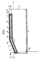
- Fig. 2 is on an enlarged scale a section substantially along the line II-II in Fig. 1.
- the numeral 1 designates a run path for long jump
- 2 designates a jumping pit.
- a take-off board 3 is located in the run path 1, at the intended distance from the jump pit 2.
- An overstep ramp 4 according to the present invention is provided in the jumping direction directly after the take-off board 3.
- the overstep ramp 4 comprises a carrier 6 of rigid, i.e. non-resilient or inflexible material, for example wood, which is detachably attached on a rigid support 5 (Fig. 2), and a step cushion 7, which is rigidly connected to the angularly designed upper surface of the carrier.
- said angle a is 150° ; i.e. the portion of the step cushion as well as of the carrier located closest to the takeoff board 3 extends upward from the take-off board 3 at an angle of 30° in relation to the horizontal plane and then is in parallel with said plane.
- the step cushion 7 comprises an upper elastic tight layer 8 of rubber or similar elastic material with high airtightness, i.e. a material which is not air-permeable, and a bottom layer 9 of the same material as in the upper layer 8 or of stiff airtight rubber or other comparable material which is not air-permeable.
- These layers or parts 8, 9, by overall wall portions 10, 10a of the same material as in the tight layer or bottom layer, are designed in one single piece or connected to each other and form between themselves a cavity 11 filled with air.
- the step cushion 7 is provided on its upper surface with a wear surface 12 of rubber coated with friction agent, which can form a separate layer rigidly connected to the layer 8 or constitute an integrated part of the layer 8, in order, especially at rainy weather, to prevent the jumper from slipping or sliding in some other way against the overstep ramp 4, even at substantial overstep.
- the step cushion 7 preferably should be located so on its carrier 6, that it rests with its edge 13 remote from the take-off board 3 against a shoulder 14 formed on the carrier 6.
- the upper surface of said shoulder should be on the same level as the wear surface 12 of the step cushion or on a slightly lower level than the same.
- a stop valve 15 shown only schematically in the drawing, it located and connected to the cavity 11. Said valve is connected through an airtight line 16 (Fig. 1) to a pressure indicator 17, to which a signal member 1 is coupled which is connected to the mains or a battery.
- said signal member 18 Upon sensing a pressure increase in the step cushion 7, said signal member 18 emits an optic and/or acoustic signal.
- the signal member 18 is shown in the form of a signal lamp emitting an optic signal in the form of red light.
- the signal member of course, can have any other suitable form, provided that the signal emitted thereby for marking overstep can be recorded and be seen and/or heard by the spectators.
- a manometer or the like which records the pressure at overstep, and which has a pointer remaining in the position of deflection, and which, thus, at least approximately can indicate the degree of overstep, i.e. whether the overstep is minute or substantial.
- the pressure increase required for the pressure indicator 17 to cause the signal member 18 to emit a signal arises as soon as a jumper contacts with the shoe the step cushion 7.
- the upper surface of said cushion thereby is subjected to a load, which presses together the cavity 11 in the step cushion 7, and thereby the air pressure in the cavity 11 increases.
- the increased air pressure in the cavity 11 of the step cushion is sensed by the pressure indicator 17, which, in its turn, causes the signal lamp 18 to light.
- the lamp by its red light shows directly to the jumper, the officials and the spectators that the jump carried out last is not okay due to overstep.
- the cavity 11 of the step cushion 7 includes air of a predetermined pressure.
- a pressure gauge (not shown) is located in a suitable place between the cushion 7 and pressure indicator 17.
- said indicator can be equipped with such a pressure gauge, and if the air pressure should change during a competition, it can be corrected either by supplying additional air, for example by means of a pump, or by tapping air via the stop valve 15 or by calibrating the pressure indicator.
- the overstep ramp 4 included in the device according to the invention is removable and is recessed into the take-off board 3 a distance which substantially corresponds to the thickness of the wall portion 10a (Fig. 2) of the step cushion.
- the edge side 20 of the take-off ramp which faces toward the jumping pit 2 is marked by a dashed line in Fig. 2. Said edge side also is the reference line, from which the length of the jump is measured.
- overstep is to be understood as false start at competitions with flying start or standing start, where the runners must not pass a reference line, i.e. a start line, before a start signal is given.
- the overstep ramp according to the invention has been shown to be straight in the drawings, but it may also be arched so as to fit a shot putter and hammer throwing ring.
Landscapes
- General Health & Medical Sciences (AREA)
- Physical Education & Sports Medicine (AREA)
- Health & Medical Sciences (AREA)
- Force Measurement Appropriate To Specific Purposes (AREA)
- Heat Treatment Of Steel (AREA)
- Optical Recording Or Reproduction (AREA)
- Television Signal Processing For Recording (AREA)
- Toys (AREA)
- Golf Clubs (AREA)
- Footwear And Its Accessory, Manufacturing Method And Apparatuses (AREA)
- Orthopedics, Nursing, And Contraception (AREA)
- Rehabilitation Tools (AREA)
- Pharmaceuticals Containing Other Organic And Inorganic Compounds (AREA)
- Fats And Perfumes (AREA)
- Medicines Containing Material From Animals Or Micro-Organisms (AREA)
Abstract
Description
- This invention relates to a device for recording overstep of a predetermined reference line by a sportsman which device comprises a step cushion having one side extending parallel to said reference line when positioned for use and including an airfilled and airtight cavity of a definite volume and an upper layer of elastic material enclosing said cavity, which layer, upon being loaded on its upper surface, is flexible to instantaneously reduce the volume of the cavity thereby causing a pressure increase, said cavity being connected to a pressure sensor which, in response to such a pressure increase, causes a signal member to emit an optical and/or acoustic signal.
- A device of the type described above for recording oversteps in connection with different sports is known from the FR-A-2 299 047. Said device includes a step cushion in the form of a tube of rubber located on the bottom of a recess. Said tube is covered by a step board also located in said recess to act on the tube. Upon being loaded on its upper surface the step board acts on the tube to reduce the volume thereof thereby causing a pressure increase being used to cause a signal member to emit a signal.
- Said known device for recording oversteps is not safe in function due to difficulties of avoiding entrance of sand particles and other undesired particles into the recess containing the tube. If such particles are allowed to enter into the recess and between the surfaces of thereof and the step board, they will reduce the movability of the step board within the recess, making said overstep recording device very insensitive and unusable in practice.
- To record oversteps in connection with exercise of sports such as long jump, hop-step-and jump and so on, an overstep bank is used, said bank consisting of a marking board located in direct connection to a take-off board and provided with a flat, smooth strand of plasteline, model clay or similar easily pliable material. The plasteline strand can be laid on a hard, not removable support or on.a removable plasteline board.
- When a jumper steps over, the overstep is recorded in the form of a mark in the smoothly formed plasteline surface. When the overstep is substantial, there is no problem for the officials to decide that overstep has occurred. When, however, the overstep is minute, it can in many cases be very difficult for the officials to decide whether or not overstep has occurred. It is, therefore, necessary at competitions to have several officials for making the decision whether overstep has occurred or not.
- When an overstep has occurred, the plasteline strand must be restored to its smooth original state. This requires time and, therefore, competitions in long jump and hop-step-and jump require relatively long time to perform, which implies for the spectators many and long uninteresting breaks. When several loose plasteline boards are available, they can be shifted, and a plasteline strand deformed by overstep can be restored during the next jump and then be exchanged against the next plasteline strand deformed by overstep.
- This known technique of marking and recording oversteps also involves the disadvantage, that the spectators at the same time as the jump is carried out cannot decide whether the jump is okay or not, but must wait for the judgment by the officials. This disadvantage also contributes to the fact that, for example, long jump and hop-step-and jump competitions are not so attractive and engaging for the spectators.
- The present invention, therefore, has the object to provide a device for overstep recording, which does not show the aforesaid disadvantages, but renders it possible, even for the spectators, to safely and directly record whether overstep has occurred or not, and which does not require any restoring work after an overstep, but rather permits a stream of jumps.
- This object is achieved in that the device according to the present invention has been given the characterizing features defined in the attached
claim 1. Preferred embodiments are defined in claims 2 to 7. - The invention is described in greater detail in the following with reference to the accompanying drawings, in which Fig. 1 is a schematic horizontal view of a long jump grounds equipped with the device according to the invention, and Fig. 2 is on an enlarged scale a section substantially along the line II-II in Fig. 1.
- In Fig. 1, the
numeral 1 designates a run path for long jump, and 2 designates a jumping pit. In therun path 1, at the intended distance from the jump pit 2, a take-offboard 3 is located. An overstep ramp 4 according to the present invention is provided in the jumping direction directly after the take-offboard 3. - The overstep ramp 4 comprises a
carrier 6 of rigid, i.e. non-resilient or inflexible material, for example wood, which is detachably attached on a rigid support 5 (Fig. 2), and astep cushion 7, which is rigidly connected to the angularly designed upper surface of the carrier. According to the present international regulations said angle a is 150°; i.e. the portion of the step cushion as well as of the carrier located closest to thetakeoff board 3 extends upward from the take-offboard 3 at an angle of 30° in relation to the horizontal plane and then is in parallel with said plane. - The
step cushion 7 comprises an upper elastic tight layer 8 of rubber or similar elastic material with high airtightness, i.e. a material which is not air-permeable, and a bottom layer 9 of the same material as in the upper layer 8 or of stiff airtight rubber or other comparable material which is not air-permeable. These layers or parts 8, 9, byoverall wall portions 10, 10a of the same material as in the tight layer or bottom layer, are designed in one single piece or connected to each other and form between themselves acavity 11 filled with air. Thestep cushion 7 is provided on its upper surface with awear surface 12 of rubber coated with friction agent, which can form a separate layer rigidly connected to the layer 8 or constitute an integrated part of the layer 8, in order, especially at rainy weather, to prevent the jumper from slipping or sliding in some other way against the overstep ramp 4, even at substantial overstep. - The
step cushion 7 preferably should be located so on itscarrier 6, that it rests with itsedge 13 remote from the take-offboard 3 against ashoulder 14 formed on thecarrier 6. The upper surface of said shoulder should be on the same level as thewear surface 12 of the step cushion or on a slightly lower level than the same. - In one short side of the step cushion a
stop valve 15, shown only schematically in the drawing, it located and connected to thecavity 11. Said valve is connected through an airtight line 16 (Fig. 1) to apressure indicator 17, to which asignal member 1 is coupled which is connected to the mains or a battery. Upon sensing a pressure increase in thestep cushion 7, saidsignal member 18 emits an optic and/or acoustic signal. In the drawings thesignal member 18 is shown in the form of a signal lamp emitting an optic signal in the form of red light. The signal member, of course, can have any other suitable form, provided that the signal emitted thereby for marking overstep can be recorded and be seen and/or heard by the spectators. It is also possible to provide as an extra signal member a manometer or the like, which records the pressure at overstep, and which has a pointer remaining in the position of deflection, and which, thus, at least approximately can indicate the degree of overstep, i.e. whether the overstep is minute or substantial. - The pressure increase required for the
pressure indicator 17 to cause thesignal member 18 to emit a signal, arises as soon as a jumper contacts with the shoe thestep cushion 7. The upper surface of said cushion thereby is subjected to a load, which presses together thecavity 11 in thestep cushion 7, and thereby the air pressure in thecavity 11 increases. The increased air pressure in thecavity 11 of the step cushion is sensed by thepressure indicator 17, which, in its turn, causes thesignal lamp 18 to light. The lamp by its red light shows directly to the jumper, the officials and the spectators that the jump carried out last is not okay due to overstep. - The
cavity 11 of thestep cushion 7 includes air of a predetermined pressure. In order to be able to control that this pressure does not change during a competition, a pressure gauge (not shown) is located in a suitable place between thecushion 7 andpressure indicator 17. Preferably said indicator can be equipped with such a pressure gauge, and if the air pressure should change during a competition, it can be corrected either by supplying additional air, for example by means of a pump, or by tapping air via thestop valve 15 or by calibrating the pressure indicator. - The overstep ramp 4 included in the device according to the invention, is removable and is recessed into the take-off board 3 a distance which substantially corresponds to the thickness of the
wall portion 10a (Fig. 2) of the step cushion. Theedge side 20 of the take-off ramp which faces toward the jumping pit 2 is marked by a dashed line in Fig. 2. Said edge side also is the reference line, from which the length of the jump is measured. - The term "overstep" is to be understood as false start at competitions with flying start or standing start, where the runners must not pass a reference line, i.e. a start line, before a start signal is given. The overstep ramp according to the invention has been shown to be straight in the drawings, but it may also be arched so as to fit a shot putter and hammer throwing ring.
Claims (7)
Priority Applications (1)
| Application Number | Priority Date | Filing Date | Title |
|---|---|---|---|
| AT83850152T ATE29668T1 (en) | 1982-06-04 | 1983-06-02 | EXCESS INDICATOR. |
Applications Claiming Priority (2)
| Application Number | Priority Date | Filing Date | Title |
|---|---|---|---|
| SE8203474 | 1982-06-04 | ||
| SE8203474A SE431167B (en) | 1982-06-04 | 1982-06-04 | OVERSEAS REGISTRATION DEVICE OVERSEAS REGISTRATION DEVICE |
Publications (2)
| Publication Number | Publication Date |
|---|---|
| EP0096672A1 EP0096672A1 (en) | 1983-12-21 |
| EP0096672B1 true EP0096672B1 (en) | 1987-09-16 |
Family
ID=20346977
Family Applications (1)
| Application Number | Title | Priority Date | Filing Date |
|---|---|---|---|
| EP83850152A Expired EP0096672B1 (en) | 1982-06-04 | 1983-06-02 | Overstep recording device |
Country Status (9)
| Country | Link |
|---|---|
| EP (1) | EP0096672B1 (en) |
| JP (1) | JPS59500999A (en) |
| AT (1) | ATE29668T1 (en) |
| AU (1) | AU568496B2 (en) |
| CA (1) | CA1232646A (en) |
| DE (1) | DE3373630D1 (en) |
| FI (1) | FI74402C (en) |
| SE (1) | SE431167B (en) |
| WO (1) | WO1983004183A1 (en) |
Families Citing this family (2)
| Publication number | Priority date | Publication date | Assignee | Title |
|---|---|---|---|---|
| CN106964142B (en) * | 2017-05-19 | 2019-01-08 | 山东大学 | Long-jump foul detection device |
| CN110665164B (en) * | 2019-10-25 | 2021-01-05 | 郑州职业技术学院 | Training device for long jump and using method |
Family Cites Families (9)
| Publication number | Priority date | Publication date | Assignee | Title |
|---|---|---|---|---|
| CH270717A (en) * | 1947-12-12 | 1950-09-15 | Automatic Telephone & Elect | Electrical switching device. |
| US2689726A (en) * | 1951-05-11 | 1954-09-21 | Frederick A Purdy | Closure-operator |
| US2858394A (en) * | 1957-06-11 | 1958-10-28 | Hopkins Russell | Pressure mat |
| US3417215A (en) * | 1966-06-22 | 1968-12-17 | Corona Thomas | Electric switch |
| DE1578536B2 (en) * | 1967-05-26 | 1976-12-23 | Fritz Burkard, Mechanische Werkstätte, 7140 Ludwigsburg | INSERT FOR CONTROL OF OVERRIDE DURING LONG JUMP |
| GB1360234A (en) * | 1971-04-16 | 1974-07-17 | Lucas Industries Ltd | Safety arrangements for road vehicles |
| FR2299047A1 (en) * | 1975-01-30 | 1976-08-27 | Gonzalez Jose | Overstep market strip for athletic jumping contests - using pulse from pneumatic tube compressed by weight to illuminate lamp on recorder |
| SU636002A1 (en) * | 1977-02-01 | 1978-12-10 | Kolesnichenko Aleksandr M | Spring device for long jumps |
| US4239979A (en) * | 1977-05-12 | 1980-12-16 | Compagnie Generale Des Etablissements Michelin | Membrane contactor |
-
1982
- 1982-06-04 SE SE8203474A patent/SE431167B/en not_active IP Right Cessation
-
1983
- 1983-06-02 DE DE8383850152T patent/DE3373630D1/en not_active Expired
- 1983-06-02 AU AU16076/83A patent/AU568496B2/en not_active Ceased
- 1983-06-02 JP JP58501894A patent/JPS59500999A/en active Pending
- 1983-06-02 WO PCT/SE1983/000221 patent/WO1983004183A1/en not_active Ceased
- 1983-06-02 EP EP83850152A patent/EP0096672B1/en not_active Expired
- 1983-06-02 AT AT83850152T patent/ATE29668T1/en not_active IP Right Cessation
- 1983-06-03 CA CA000429608A patent/CA1232646A/en not_active Expired
-
1984
- 1984-01-25 FI FI840307A patent/FI74402C/en not_active IP Right Cessation
Also Published As
| Publication number | Publication date |
|---|---|
| CA1232646A (en) | 1988-02-09 |
| JPS59500999A (en) | 1984-06-07 |
| FI74402C (en) | 1988-02-08 |
| FI840307L (en) | 1984-01-25 |
| FI74402B (en) | 1987-10-30 |
| FI840307A0 (en) | 1984-01-25 |
| DE3373630D1 (en) | 1987-10-22 |
| ATE29668T1 (en) | 1987-10-15 |
| EP0096672A1 (en) | 1983-12-21 |
| AU568496B2 (en) | 1988-01-07 |
| WO1983004183A1 (en) | 1983-12-08 |
| AU1607683A (en) | 1983-12-16 |
| SE431167B (en) | 1984-01-23 |
| SE8203474L (en) | 1983-12-05 |
Similar Documents
| Publication | Publication Date | Title |
|---|---|---|
| US4051616A (en) | Rod with strike signalling apparatus | |
| US4276711A (en) | Fishing rod with strike signalling apparatus | |
| EP3189742B1 (en) | Sound-producing shoe including impact and proximity detectors | |
| US6499339B1 (en) | Method and an apparatus for measuring the load-bearing capacity of a road surface | |
| US11183017B1 (en) | Apparatus and method for detecting a won prize in a claw machine | |
| US4395826A (en) | Apparatus for determining a foot size | |
| EP0096672A1 (en) | Overstep recording device | |
| EP1890778B1 (en) | Putting practice aid | |
| US2737392A (en) | Putting target device | |
| US1094236A (en) | Device for use in connection with practising golf. | |
| US6378808B1 (en) | Device for releasing a parachute | |
| US5003820A (en) | Electronic speedometer for snow skis | |
| GB2200732A (en) | Shooting game apparatus | |
| KR200200026Y1 (en) | Golf shoes installed with levleing instrument | |
| US20020107623A1 (en) | Apparatus for automatically ascertaining the setting for ski bindings | |
| KR100651061B1 (en) | Golf Ball Supply Device | |
| JP2709537B2 (en) | Test piece for measuring shot blast strength and method for measuring shot blast strength | |
| JPS6361626B2 (en) | ||
| ATE215213T1 (en) | SHOOTING TARGET WITH ELECTRONIC HIT INDICATOR | |
| JPS5988175A (en) | Golf club for training | |
| JPH08112397A (en) | Game machine with game play timer | |
| JPS54125004A (en) | Pickup arm control device of record players | |
| US2316990A (en) | Bowling alley | |
| WO2003011406A1 (en) | A method for measuring the length of a sports performance | |
| JPS6427572A (en) | Shoes for karate game |
Legal Events
| Date | Code | Title | Description |
|---|---|---|---|
| PUAI | Public reference made under article 153(3) epc to a published international application that has entered the european phase |
Free format text: ORIGINAL CODE: 0009012 |
|
| AK | Designated contracting states |
Designated state(s): AT BE CH DE FR GB IT LI LU NL |
|
| 17P | Request for examination filed |
Effective date: 19840612 |
|
| GRAA | (expected) grant |
Free format text: ORIGINAL CODE: 0009210 |
|
| AK | Designated contracting states |
Kind code of ref document: B1 Designated state(s): AT BE CH DE FR GB IT LI LU NL |
|
| REF | Corresponds to: |
Ref document number: 29668 Country of ref document: AT Date of ref document: 19871015 Kind code of ref document: T |
|
| REF | Corresponds to: |
Ref document number: 3373630 Country of ref document: DE Date of ref document: 19871022 |
|
| ET | Fr: translation filed | ||
| ITF | It: translation for a ep patent filed | ||
| PG25 | Lapsed in a contracting state [announced via postgrant information from national office to epo] |
Ref country code: LU Free format text: LAPSE BECAUSE OF NON-PAYMENT OF DUE FEES Effective date: 19880630 |
|
| PLBE | No opposition filed within time limit |
Free format text: ORIGINAL CODE: 0009261 |
|
| STAA | Information on the status of an ep patent application or granted ep patent |
Free format text: STATUS: NO OPPOSITION FILED WITHIN TIME LIMIT |
|
| 26N | No opposition filed | ||
| PG25 | Lapsed in a contracting state [announced via postgrant information from national office to epo] |
Ref country code: AT Effective date: 19890602 |
|
| PG25 | Lapsed in a contracting state [announced via postgrant information from national office to epo] |
Ref country code: BE Effective date: 19890630 Ref country code: CH Effective date: 19890630 Ref country code: LI Effective date: 19890630 |
|
| PGFP | Annual fee paid to national office [announced via postgrant information from national office to epo] |
Ref country code: DE Payment date: 19891212 Year of fee payment: 7 |
|
| PGFP | Annual fee paid to national office [announced via postgrant information from national office to epo] |
Ref country code: FR Payment date: 19891219 Year of fee payment: 7 |
|
| BERE | Be: lapsed |
Owner name: GUSTAV LINDMARK & SONER I UMEA A.B. Effective date: 19890630 |
|
| PGFP | Annual fee paid to national office [announced via postgrant information from national office to epo] |
Ref country code: GB Payment date: 19891231 Year of fee payment: 7 |
|
| PG25 | Lapsed in a contracting state [announced via postgrant information from national office to epo] |
Ref country code: NL Effective date: 19900101 |
|
| NLV4 | Nl: lapsed or anulled due to non-payment of the annual fee | ||
| REG | Reference to a national code |
Ref country code: CH Ref legal event code: PL |
|
| PG25 | Lapsed in a contracting state [announced via postgrant information from national office to epo] |
Ref country code: GB Effective date: 19900602 |
|
| GBPC | Gb: european patent ceased through non-payment of renewal fee | ||
| PG25 | Lapsed in a contracting state [announced via postgrant information from national office to epo] |
Ref country code: FR Effective date: 19910228 |
|
| PG25 | Lapsed in a contracting state [announced via postgrant information from national office to epo] |
Ref country code: DE Effective date: 19910301 |
|
| REG | Reference to a national code |
Ref country code: FR Ref legal event code: ST |