EP0095300A2 - Vehicle mounted Doppler radar system - Google Patents
Vehicle mounted Doppler radar system Download PDFInfo
- Publication number
- EP0095300A2 EP0095300A2 EP83302768A EP83302768A EP0095300A2 EP 0095300 A2 EP0095300 A2 EP 0095300A2 EP 83302768 A EP83302768 A EP 83302768A EP 83302768 A EP83302768 A EP 83302768A EP 0095300 A2 EP0095300 A2 EP 0095300A2
- Authority
- EP
- European Patent Office
- Prior art keywords
- vehicle
- signals
- doppler
- output
- doppler radar
- Prior art date
- Legal status (The legal status is an assumption and is not a legal conclusion. Google has not performed a legal analysis and makes no representation as to the accuracy of the status listed.)
- Granted
Links
- 238000001514 detection method Methods 0.000 claims description 3
- 230000001360 synchronised effect Effects 0.000 claims description 3
- 230000000630 rising effect Effects 0.000 claims description 2
- 230000000694 effects Effects 0.000 description 8
- 238000006073 displacement reaction Methods 0.000 description 6
- 230000008901 benefit Effects 0.000 description 5
- 238000012935 Averaging Methods 0.000 description 4
- 238000005259 measurement Methods 0.000 description 4
- 230000008859 change Effects 0.000 description 3
- 238000012545 processing Methods 0.000 description 3
- 238000010586 diagram Methods 0.000 description 2
- 238000000034 method Methods 0.000 description 2
- 230000004044 response Effects 0.000 description 2
- 230000003595 spectral effect Effects 0.000 description 2
- 229910000497 Amalgam Inorganic materials 0.000 description 1
- 230000003466 anti-cipated effect Effects 0.000 description 1
- 238000013459 approach Methods 0.000 description 1
- 239000002131 composite material Substances 0.000 description 1
- 238000010276 construction Methods 0.000 description 1
- 230000001419 dependent effect Effects 0.000 description 1
- 230000009977 dual effect Effects 0.000 description 1
- 238000009434 installation Methods 0.000 description 1
- 230000004048 modification Effects 0.000 description 1
- 238000012986 modification Methods 0.000 description 1
- 230000008569 process Effects 0.000 description 1
- 230000035945 sensitivity Effects 0.000 description 1
- 238000001228 spectrum Methods 0.000 description 1
- 239000007921 spray Substances 0.000 description 1
Images




Classifications
-
- G—PHYSICS
- G01—MEASURING; TESTING
- G01S—RADIO DIRECTION-FINDING; RADIO NAVIGATION; DETERMINING DISTANCE OR VELOCITY BY USE OF RADIO WAVES; LOCATING OR PRESENCE-DETECTING BY USE OF THE REFLECTION OR RERADIATION OF RADIO WAVES; ANALOGOUS ARRANGEMENTS USING OTHER WAVES
- G01S13/00—Systems using the reflection or reradiation of radio waves, e.g. radar systems; Analogous systems using reflection or reradiation of waves whose nature or wavelength is irrelevant or unspecified
- G01S13/02—Systems using reflection of radio waves, e.g. primary radar systems; Analogous systems
- G01S13/50—Systems of measurement based on relative movement of target
- G01S13/58—Velocity or trajectory determination systems; Sense-of-movement determination systems
- G01S13/60—Velocity or trajectory determination systems; Sense-of-movement determination systems wherein the transmitter and receiver are mounted on the moving object, e.g. for determining ground speed, drift angle, ground track
-
- B—PERFORMING OPERATIONS; TRANSPORTING
- B60—VEHICLES IN GENERAL
- B60T—VEHICLE BRAKE CONTROL SYSTEMS OR PARTS THEREOF; BRAKE CONTROL SYSTEMS OR PARTS THEREOF, IN GENERAL; ARRANGEMENT OF BRAKING ELEMENTS ON VEHICLES IN GENERAL; PORTABLE DEVICES FOR PREVENTING UNWANTED MOVEMENT OF VEHICLES; VEHICLE MODIFICATIONS TO FACILITATE COOLING OF BRAKES
- B60T2250/00—Monitoring, detecting, estimating vehicle conditions
- B60T2250/04—Vehicle reference speed; Vehicle body speed
Definitions
- the present invention relates to Doppler Radar Systems and more particularly to a radar system for mounting on a vehicle to give an indication of the speed of such a vehicle.
- the present invention therefore uses a direction sensing module and novel data processing to enhance rejection of vibrationally induced erroneous doppler signals. This enables very low speeds to be measured, even when the radar platform is vibrating.
- the vibrationally induced false doppler signals are treated as direction sensitive displacement measurements which are "integrated" in a true displacement averaging circuit.
- the composite system retains the ability to operate at very low speeds, and also has the advantage of compensation for tilt induced errors.
- a doppler radar system for mounting on a vehicle including means for obtaining quadrature doppler frequency output signals from respective detectors, amplifying means for amplifying and squaring the output signals, including logic means for producing from said amplified and squared signals two pulse trains indicative of forward and reverse motion and including combining means for combining together said forward and reverse pulse trains to produce an output proportional to the forward motion of the vehicle substantially independent of the vibration of the vehicle.
- a vehicle mounted doppler radar system including a first, forward looking doppler radar and a second rearward looking doppler radar in which each of said first and second doppler radar systems comprises a quadrature mixer in which both in phase and quadrature signal outputs are produced, in which the in phase and quadrature outputs are combined to produce first and second signals and in which said first and second signals are combined to produce a third output signal which is proportional to the speed of the vehicle and in which the third output signal is substantially insensitive to the tilting of the vehicle and to the vibration of the vehicle.
- a simple doppler radar with a single mixer, balanced mixer or using the active element (gunn, impatt ”) as the mixing element can be used to measure ground speed under ideal conditions.
- the doppler signal at the mixer fD is given by Vg is the true ground speed m/sec
- the transmitter can operate anywhere in the electromagnetic spectrum, or can use ultrasonics, in which case C is the speed of sound.
- Vgo 4fmAtan6.
- Vgmin 2 ⁇ £mAtan0
- Figure 5 shows how the doppler frequency f D due to the true ground speed is frequency modulated in the presence of vertical vibration to produce an indicated doppler frequency fD.
- Vg ⁇ 2 ⁇ £mAtan0 Vgmin
- the FD averaged over a period that is long compared to 1/fm will equal the true doppler frequency fD .
- this radar is similar to that in Figure 1, but the receiver is configured with a quadrature mixer, whereby the doppler signal is available at two ports, but in phase quadrature.
- the receiver is configured with a quadrature mixer, whereby the doppler signal is available at two ports, but in phase quadrature.
- I.F. quadrature I.F.
- the directional information can be used to prevent the "rectification" of fD' at low values of Vg in conditions of vibration (on vertical modulation of the target).
- the information detection of the directional information can be achieved in several ways. For single targets with a high signal/clutter ratio it is only necessary to look at the lead/lag relationship between the two doppler signals. If the lead/lag decision is made at every zero crossing of the doppler signals from both mixers, and a pulse is generated at every zero crossing and subsequently steered into two channels, dependent on the lead/lag decision, then two pulse trains will be generated, one corresponding to forward displacements and the other backwards displacements with respect to the intended direction of travel. The pulse stream frequency will be a 4 times the doppler frequency.
- Each pulse corresponds to a fixed displacement of the radar relative to the ground, as the pulse rate is proportional to speed.
- the two pulse trains when subtracted and averaged over a time period long compared to 1/fm will now give the true mean doppler frequency, and so under conditions of vibration with low ground speed the indicated doppler speed now equals the true ground speed.
- FIG. 4 With reference to Figure 4 there is shown a direction sensing Janus radar. This system is an amalgam of the simple direction sensing radar and the Janus configuration. The doppler signals in the presence of vibration are shown in figure 8.
- FIG 9 there is shown in block diagrammatic form the circuitry for the invention as described with reference to figure 2.
- the two inputs sin wd and cos wd are obtained from for example a Gunn diode direction sensing module 10 comprising a Gunn diode 12 and first and second sensors 14, 16.
- the Gunn diode 12 emits a high frequency signal (several GHz) which is mixed with the reflected signal from the ground to give quadrature output signals cos wd and sin wd.
- the signals are in quadrature because of the physical spacing S between the detectors 14 and 16.
- the signals sin wd and cos wd which carry the doppler frequency information will be referenced a and b respectively.
- These signals are both amplified in respective high gain amplifiers 18, 20 to give square wave output signals A and B.
- Signals A and B are fed to respective clock synchronisation circuits 22, 24 where the rising edges of each of the pulses is clocked with clock pulses ⁇ o and ⁇ 2 and falling edge with clock pulses 0 ⁇ 1 and 0 ⁇ 3 .
- the four phase clock is generated by dividing down a 2MHz clock into four or eight individual clock pulse trains.
- each pulse train has a rate of 500KHz and for eight phase at 250KHz.
- the eight phase clock is required for the embodiment of figures 4 and 11 to be described hereinafter.
- the anticipated Doppler frequency will be of the order of less than 10KHz so it may be seen that each edge of the waveform A or B can be fairly accurately clocked in synchronism with clock pulses which are at least twenty five times the Doppler frequency.
- the pulse trains AUP, ADOWN, BUP, BDOWN are fed to a forward/reverse sensing circuit 26. In this circuit they are compared with the signals A and B by for example ANDing the signals together to produce forward and reverse pulse trains on outputs 28 and 30 respectively. This process is explained with reference to the timing diagram of figure 10.
- the forward output 28 is shown. If the vehicle on which the radar is mounted is moving forward without any vibration the AUP is ANDed with A to give first output pulse, ADOWN will be ANDed with A to give a second output pulse, BUP will be ANDed with B to give a third output pulse and BDOWN with B to give a fourth output pulse. If there is vibration in the system or other reasons to cause a phase change in the outputs cos wd and sin wd then the synchronism will be lost as shown in the right hand side of figure 10. With such a phase change indicated at 32 the output from the forward output 28 will cease because the signals AUP etc will not be ANDed with the signals A, B to give outputs.
- the forward pulses are passed straight through a pulse steering network 34 to an output 36.
- the pulse repetition rate will be a proportional measure of the speed of the vehicle at output 36.
- the pulse steering network detects this and feeds this pulse to the UP input of an up/down counter 38 which is normally set at zero.
- the up/down counter will continue to count upwards for each reverse pulse received.
- the pulse steering network 34 will be controlled by output 40 such that it can not output any more pulses to output 36 until the up/down counter has been returned to a zero state. This can be done by a simple AND function gating arrangement or by a flip-flop or other suitable means.
- the reverse pulses cease the forward pulses are fed to the down input of the up/down counter until it is returned to its zero state. Again this is accomplished with a simple logic gate controlled by the output of up/down counter 38.
- a detector detects this as acknowledging that the vehicle is in reverse and outputs a signal on line 42 to supply an input to one input of an exclusive NOR gate 44 which effects a complete phase reversal (180°) to the B input causing B to lead A instead of the other way round. This then causes reversal of outputs 28 and 30 and thus the reverse direction is compensated for.
- Counter 38 will be counted back down to its zero state. The delay in read out will be relatively short whilst counter 38 counts up to its full state and following reversal back to a zero state.
- figure 11 With reference to figure 11 the arrangement for the configuration of figure 4 is shown. There are four inputs a, b, c and d as shown in figure 4. Two will be as in figure 2, 9, and the other two c and d will be from the radar looking in the opposite direction.
- a second forward/reverse network is provided to give forward and reverse pulses for outputs c and d and both sets of forward and reverse pulses are combined in OR gates 50, 52 to give combined output pulse trains on outputs 28 and 30 (see figure 9). From there the pulse trains are processed as in figure 9 to give the desired output and direction reversal.
Landscapes
- Engineering & Computer Science (AREA)
- Radar, Positioning & Navigation (AREA)
- Remote Sensing (AREA)
- Computer Networks & Wireless Communication (AREA)
- Physics & Mathematics (AREA)
- General Physics & Mathematics (AREA)
- Radar Systems Or Details Thereof (AREA)
Abstract
Description
- The present invention relates to Doppler Radar Systems and more particularly to a radar system for mounting on a vehicle to give an indication of the speed of such a vehicle.
- There are particular problems where the speed of a slow moving vehicle requires to be assessed with accuracy. Previously known radars when mounted on such a vehicle produce inaccurate results due to the tilting and/or the vibration of the vehicle which affects the output of the Doppler radar which is attempting to measure the relative movement between the vehicle and the ground. In such cases it has been found more accurate to use a mechanical arrangement associated with the wheels of the vehicle but this has the disadvantage that where slipping of the wheels often occurs such as in the case of agricultural tractors an equally inaccurate speed measurement is produced. Where the speed measurement is used for example to control the rate of application of a spray this can lead to overspraying which can be extremely serious. Thus it is extremely important to be able to accurately measure the forward (or backward) speed of movement of a vehicle and the present invention seeks to provide for such a measurement.
- It is an object of the present invention to provide a doppler sensing radar with the following paramenters.
- 1. High Accuracy
- 2. Fast Response Time
- 3. Insensitivity to Installation Errors
- 4. Simple Construction
- 5. Minimisation of Errors due to Vibration
- The present invention therefore uses a direction sensing module and novel data processing to enhance rejection of vibrationally induced erroneous doppler signals. This enables very low speeds to be measured, even when the radar platform is vibrating. The vibrationally induced false doppler signals are treated as direction sensitive displacement measurements which are "integrated" in a true displacement averaging circuit.
- By combining two radars of the type described above into a Janus configuration, further advantages are gained. The composite system retains the ability to operate at very low speeds, and also has the advantage of compensation for tilt induced errors.
- (Previously published Janus configured systems do not cancel vibrationally induced errors if the platform speed is below a threshold).
- According to the present invention there is provided a doppler radar system for mounting on a vehicle including means for obtaining quadrature doppler frequency output signals from respective detectors, amplifying means for amplifying and squaring the output signals, including logic means for producing from said amplified and squared signals two pulse trains indicative of forward and reverse motion and including combining means for combining together said forward and reverse pulse trains to produce an output proportional to the forward motion of the vehicle substantially independent of the vibration of the vehicle.
- According the the present invention there is also provided a vehicle mounted doppler radar system including a first, forward looking doppler radar and a second rearward looking doppler radar in which each of said first and second doppler radar systems comprises a quadrature mixer in which both in phase and quadrature signal outputs are produced, in which the in phase and quadrature outputs are combined to produce first and second signals and in which said first and second signals are combined to produce a third output signal which is proportional to the speed of the vehicle and in which the third output signal is substantially insensitive to the tilting of the vehicle and to the vibration of the vehicle.
- Embodiments of the present invention will now be described with reference to the accompanying drawings in which,
- Figure 1 shows a simple doppler radar with a single mixer,
- Figure 2 shows a modification of the radar system of Figure 1 on which the receiver is configured with a quadrature mixer,
- Figure 3 shows a simple Janus radar system,
- Figure 4 shows a direction sensing Janus radar system,
- Figure 5 shows a number of graphs showing the effects of vertical vibration on the system of Figure 1,
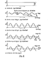
- Figure 6 shows a number of graphs showing the effects of vertical vibration on the system of Figure 2,
- Figure 7 shows a number of graphs showing the effects of vertical vibration on the system of Figure 3,
- Figure 8 shows a number of graphs showing the effects of vertical vibration on the system of Figure 4,
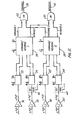
- Figures 9, 9a show in block diagrammatic form circuitry for the arrangement of figure 2 in accordance with the present invention,
- Figure 10 shows a timing diagram for the forward/reverse sensing circuit of figure 9 and,
- Figure 11 shows in block diagrammatic form circuitry for the arrangement of figure 4 in accordance with the present invention.
- Referring now to Figure 1, a simple doppler radar (with a single mixer, balanced mixer or using the active element (gunn, impatt ...) as the mixing element can be used to measure ground speed under ideal conditions.
- The doppler signal at the mixer fD is given by

- f is the transmitter frequency Hz
- C is the speed of light m/sec
- 00 is the included angle between ground and principal axis of transmitter beam.
- The transmitter can operate anywhere in the electromagnetic spectrum, or can use ultrasonics, in which case C is the speed of sound.
- The system of Figure 1 however has the following limitations:-Tilt
- If the angle 6 changes or is incorrectly set, then the apparent speed Vg will be in error. This is particularly a problem where the radar platform orientation changes due to variable loading of the vehicle etc. If
-

- Assume the radar platform has a vertical sinusoidal displacement of Apk, with a vibrational frequency fm. The simple radar will result in an indicated ground speed Vgo when the true ground speed Vg is zero.
- This is true of all radars, ultrasonic, microwave or laser. It can be shown that the true ground speed Vg must must exceed a threshold speed Vgmin, before the average indicated speed is equal to the true ground speed. For Vg<Vgmin, the averaged value of the indicated speed always exceeds the true ground speed.
- Figure 5 shows how the doppler frequency fD due to the true ground speed is frequency modulated in the presence of vertical vibration to produce an indicated doppler frequency fD.
- For Vg≤ 2Π £mAtan0 = Vgmin, the FD averaged over a period that is long compared to 1/fm will equal the true doppler frequency fD .
- If Vg <Vgmin, then fD' undergoes a phase reversal as fD' instantaneously goes to zero. In a simple pulse counting system, the value of fD' is effectively rectified, leading to fD mean> fD. Hence at low speeds, false readings will result.
- In summary therefore the simple radar of Figure 1 has the following limitations.
- i. sensitivity to tilt
- ii. inability to give accurate results when Vg < Vgmin.
- Referring now to Figure 2, this radar is similar to that in Figure 1, but the receiver is configured with a quadrature mixer, whereby the doppler signal is available at two ports, but in phase quadrature. By using two mixer elements and a quadrature I.F. it is possible to measure velocity rather than speed. The directional information can be used to prevent the "rectification" of fD' at low values of Vg in conditions of vibration (on vertical modulation of the target).
- The information detection of the directional information can be achieved in several ways. For single targets with a high signal/clutter ratio it is only necessary to look at the lead/lag relationship between the two doppler signals. If the lead/lag decision is made at every zero crossing of the doppler signals from both mixers, and a pulse is generated at every zero crossing and subsequently steered into two channels, dependent on the lead/lag decision, then two pulse trains will be generated, one corresponding to forward displacements and the other backwards displacements with respect to the intended direction of travel. The pulse stream frequency will be a 4 times the doppler frequency.
- In simple systems it is normally sufficient to look at this relative phasing once per doppler cycle of one of the mixers, though the present method, equivalent to 4 times per doppler cycle, improves the data rate and hence the response time, and also greatly improves noise rejection.
- Each pulse corresponds to a fixed displacement of the radar relative to the ground, as the pulse rate is proportional to speed. The two pulse trains when subtracted and averaged over a time period long compared to 1/fm will now give the true mean doppler frequency, and so under conditions of vibration with low ground speed the indicated doppler speed now equals the true ground speed.
- The limitations of this system are:-
- i. unit is still sensitive to tilt vibrations
- ii. averaging period ) 1/fm.
- The advantages of the system are however:-
- i. Insensitive to vibration
- ii. Higher data rate
- iii. Improved rejection of noise and vibrational clutter.
- Referring now to Figure 3, this type of system is well known. Dual and four beam systems are used in doppler navigators in aircraft. For low speed use under conditions of vibration, such a configuration has the same low speed threshold, Vgmin as the simple system of Figure 1. However, at speeds> Vgmin the vibrational modulation on the doppler signals of both mixers are in antiphase, and so when the pulse trains are interlaced, the vibrational components cancel, and the desired signals reinforce.
- The principal reason for the Janus configuration is to limit the effects of tilt. With this type of radar, variations in 0 due to the radar platform tend to cancel. The error is (1-cosδ). The doppler signals at the mixers are shown in Figure 7.
- The principle limitation of this system is that it is still subject to threshold speeds Vgmin = 2 π fmtanθ for accurate speed indication.
- Its advantages are as follows:-
- i. Insensitive to tilt variations
- ii. Averaging period to remove vibrational effects = 0 (Vg≥ Vgmin)
- iii. Data rate as high as Simple Direction Sensing radar.
- iv. Spectral bandwidth reduced by r2 due to uncorrellated signals from the mixers.
- With reference to Figure 4 there is shown a direction sensing Janus radar. This system is an amalgam of the simple direction sensing radar and the Janus configuration. The doppler signals in the presence of vibration are shown in figure 8.
- The advantages of this system are:-
- i. Insensitive to tilt
- ii. Averaging period to remove vibrational effects ≈ 0.
- iii. Vgmin = 0
- iv. Very high data rate (8 times doppler frequency)
- v. Good noise and vibrational clutter rejection
- vi. Spectral bandwidth reduced by √2 due to incorrellated signals from the front and rear radars.
- With reference now to figure 9 there is shown in block diagrammatic form the circuitry for the invention as described with reference to figure 2.
- The two inputs sin wd and cos wd are obtained from for example a Gunn diode
direction sensing module 10 comprising aGunn diode 12 and first andsecond sensors 14, 16. In operation theGunn diode 12 emits a high frequency signal (several GHz) which is mixed with the reflected signal from the ground to give quadrature output signals cos wd and sin wd. The signals are in quadrature because of the physical spacing S between thedetectors 14 and 16. - For convenience the signals sin wd and cos wd which carry the doppler frequency information will be referenced a and b respectively. These signals are both amplified in respective
high gain amplifiers clock synchronisation circuits - The four phase clock is generated by dividing down a 2MHz clock into four or eight individual clock pulse trains. For a four phase clock each pulse train has a rate of 500KHz and for eight phase at 250KHz. The eight phase clock is required for the embodiment of figures 4 and 11 to be described hereinafter. The anticipated Doppler frequency will be of the order of less than 10KHz so it may be seen that each edge of the waveform A or B can be fairly accurately clocked in synchronism with clock pulses which are at least twenty five times the Doppler frequency. Thus the AUP, ADOWN, BUP and BDOWN pulse trains will be clearly distinguishable in pulse timing. The pulse trains AUP, ADOWN, BUP, BDOWN are fed to a forward/
reverse sensing circuit 26. In this circuit they are compared with the signals A and B by for example ANDing the signals together to produce forward and reverse pulse trains onoutputs - In figure 10 the
forward output 28 is shown. If the vehicle on which the radar is mounted is moving forward without any vibration the AUP is ANDed with A to give first output pulse, ADOWN will be ANDed with A to give a second output pulse, BUP will be ANDed with B to give a third output pulse and BDOWN with B to give a fourth output pulse. If there is vibration in the system or other reasons to cause a phase change in the outputs cos wd and sin wd then the synchronism will be lost as shown in the right hand side of figure 10. With such a phase change indicated at 32 the output from theforward output 28 will cease because the signals AUP etc will not be ANDed with the signals A, B to give outputs. Thus no outputs will appear at 28 but a pulse train will appear atoutput 30 where the signals AUP etc are with other combinations of A and B to give outputs when a reverse or disturbed motion is present. The logic function of sensing synchronism of the pulses may be accomplished by AND or NAND functions since it may be seen from the dotted lines in figure 10 that the slightest change in synchronism of say pulse AUP with pulse A will result in a loss of an output pulse. - Thus on output 28 a forward pulse train is produced which will be the normal output. Only if there is vibration etc to result in loss of synchronism will pulses appear on the
reverse output 30. - For normal operation the forward pulses are passed straight through a
pulse steering network 34 to an output 36. The pulse repetition rate will be a proportional measure of the speed of the vehicle at output 36. - If however a reverse pulse is output on
output 30 because of vibration etc then the pulse steering network detects this and feeds this pulse to the UP input of an up/down counter 38 which is normally set at zero. The up/down counter will continue to count upwards for each reverse pulse received. Thepulse steering network 34 will be controlled byoutput 40 such that it can not output any more pulses to output 36 until the up/down counter has been returned to a zero state. This can be done by a simple AND function gating arrangement or by a flip-flop or other suitable means. Thus when the reverse pulses cease the forward pulses are fed to the down input of the up/down counter until it is returned to its zero state. Again this is accomplished with a simple logic gate controlled by the output of up/downcounter 38. - The net result normally is that for vibratory conditions the pulse train output at output 36 will be an interrupted one, the interruptions occurring each time a reverse pulse is received. Thus if the vehicle is stationary and is vibrating there will be as many reverse pulses as forward pulses and the net output on output 36 will be zero. If the direction of motion of the vehicle is actually reversed then obviously the majority of pulses will be output on
line 30 and the up/down counter will rapidly approach a full state. The maximum number stored by the counter is arranged such that this full state could not be reached by vibration or other non-synchronous problems. Thus when the full state is achieved a detector detects this as acknowledging that the vehicle is in reverse and outputs a signal online 42 to supply an input to one input of an exclusive NORgate 44 which effects a complete phase reversal (180°) to the B input causing B to lead A instead of the other way round. This then causes reversal ofoutputs Counter 38 will be counted back down to its zero state. The delay in read out will be relatively short whilst counter 38 counts up to its full state and following reversal back to a zero state. - With reference to figure 11 the arrangement for the configuration of figure 4 is shown. There are four inputs a, b, c and d as shown in figure 4. Two will be as in figure 2, 9, and the other two c and d will be from the radar looking in the opposite direction.
- The processing of the signals c and d is similar to that for a and b as previously described except that the remaining four clocks Ø4 to 0̸7 are used to ensure complete operation of all pulses. The same reference numerals with dashes indicate similar processing circuitry. A second forward/reverse network is provided to give forward and reverse pulses for outputs c and d and both sets of forward and reverse pulses are combined in OR
gates outputs 28 and 30 (see figure 9). From there the pulse trains are processed as in figure 9 to give the desired output and direction reversal.
Claims (8)
Applications Claiming Priority (2)
| Application Number | Priority Date | Filing Date | Title |
|---|---|---|---|
| GB8215268 | 1982-05-25 | ||
| GB8215268 | 1982-05-25 |
Publications (3)
| Publication Number | Publication Date |
|---|---|
| EP0095300A2 true EP0095300A2 (en) | 1983-11-30 |
| EP0095300A3 EP0095300A3 (en) | 1984-05-23 |
| EP0095300B1 EP0095300B1 (en) | 1987-10-21 |
Family
ID=10530616
Family Applications (1)
| Application Number | Title | Priority Date | Filing Date |
|---|---|---|---|
| EP83302768A Expired EP0095300B1 (en) | 1982-05-25 | 1983-05-17 | Vehicle mounted doppler radar system |
Country Status (9)
| Country | Link |
|---|---|
| US (1) | US4635059A (en) |
| EP (1) | EP0095300B1 (en) |
| JP (1) | JPS5967478A (en) |
| AU (1) | AU556782B2 (en) |
| CA (1) | CA1214243A (en) |
| DE (1) | DE3374149D1 (en) |
| GB (1) | GB2122834B (en) |
| IN (1) | IN157457B (en) |
| ZA (1) | ZA833783B (en) |
Cited By (10)
| Publication number | Priority date | Publication date | Assignee | Title |
|---|---|---|---|---|
| EP0389670A3 (en) * | 1989-03-23 | 1991-03-27 | VDO Adolf Schindling AG | Apparatus for measuring the speed of a vehicle according to the Doppler radar principle. |
| WO1992001951A1 (en) * | 1990-07-26 | 1992-02-06 | Brelenstar Limited | Microwave transmitter-receiver radar device |
| WO2023169652A1 (en) * | 2022-03-07 | 2023-09-14 | Volvo Truck Corporation | Radar systems for determining vehicle speed over ground |
| WO2023237559A1 (en) * | 2022-06-07 | 2023-12-14 | Modell- Und Formenbau Blasius Gerg Gmbh | Radar system having two radar sensors for determining the ground speed of a land vehicle, and method |
| DE102022210430A1 (en) | 2022-09-30 | 2024-04-04 | Siemens Mobility GmbH | Arrangement for determining the speed over ground of a rail vehicle |
| WO2024217670A1 (en) | 2023-04-18 | 2024-10-24 | Volvo Truck Corporation | A ground speed radar in virtual janus configuration |
| WO2024217735A1 (en) | 2023-04-18 | 2024-10-24 | Volvo Truck Corporation | Radar systems for real time estimation of vehicle pivot axes |
| WO2024217669A1 (en) | 2023-04-18 | 2024-10-24 | Volvo Truck Corporation | Multi-band ground radar transceiver systems |
| WO2024217668A1 (en) | 2023-04-18 | 2024-10-24 | Volvo Truck Corporation | Notch-based slip angle estimation for ground speed radars |
| EP4459313A1 (en) | 2023-05-01 | 2024-11-06 | Volvo Truck Corporation | Radar-based wheel end modules for determining wheel force generating capability |
Families Citing this family (17)
| Publication number | Priority date | Publication date | Assignee | Title |
|---|---|---|---|---|
| US5422646A (en) * | 1983-02-24 | 1995-06-06 | The United States Of America As Represented By The Secretary Of The Navy | High frequency MTI radar |
| AU575396B2 (en) * | 1984-05-14 | 1988-07-28 | Deere & Company | Ground speed sensor |
| JPS6114586A (en) * | 1984-06-30 | 1986-01-22 | Iseki & Co Ltd | Ground vehicle speed detection device |
| US4728954A (en) * | 1984-12-20 | 1988-03-01 | Deere & Company | Ground velocity sensor with drop-out detection |
| DE3835510C2 (en) * | 1987-10-30 | 1999-01-07 | Volkswagen Ag | Device based on the Doppler principle for determining the distance covered by a vehicle |
| GB2221591A (en) * | 1988-08-06 | 1990-02-07 | Marconi Gec Ltd | Optical vehicle speedometer |
| US5621413A (en) * | 1995-06-27 | 1997-04-15 | Motorola Inc. | Vehicle-ground surface measurement system |
| CN1215475A (en) * | 1996-03-29 | 1999-04-28 | 株式会社小松制作所 | Vehicle Speed Detection System |
| AU6633798A (en) | 1998-03-09 | 1999-09-27 | Gou Lite Ltd. | Optical translation measurement |
| US7218271B2 (en) * | 2001-08-16 | 2007-05-15 | Applied Concepts, Inc. | System and method for determining patrol speed |
| US6580386B1 (en) * | 2001-08-16 | 2003-06-17 | Applied Concepts, Inc. | System and method for processing radar data |
| DE102008038615A1 (en) * | 2007-09-18 | 2009-03-19 | Continental Teves Ag & Co. Ohg | Sensor device and method for detecting the movement of a vehicle |
| DE102010038541A1 (en) * | 2010-07-28 | 2012-02-02 | Continental Teves Ag & Co. Ohg | Sensor arrangement for detecting spring travel and/or spring velocity in motor car, has evaluation circuit determining radiation based on reflected radiation of spring travel and/or velocity of gears or gear part and/or dependent variable |
| DE102011078989A1 (en) * | 2011-07-12 | 2013-01-17 | Robert Bosch Gmbh | Method and radar sensor for distinguishing between forward driving and reverse driving in a vehicle |
| US9500747B2 (en) * | 2012-01-10 | 2016-11-22 | Mitsubishi Electric Corporation | Travel distance measurement device |
| US10705105B2 (en) | 2017-07-21 | 2020-07-07 | Applied Concepts, Inc. | Absolute speed detector |
| WO2024158581A1 (en) * | 2023-01-23 | 2024-08-02 | Parker-Hannifin Corporation | Systems and methods for enhancing ground speed determination for a vehicle |
Family Cites Families (17)
| Publication number | Priority date | Publication date | Assignee | Title |
|---|---|---|---|---|
| US3092832A (en) * | 1959-03-06 | 1963-06-04 | Bendix Corp | Closure signal system |
| US3181148A (en) * | 1959-03-30 | 1965-04-27 | Bendix Corp | Selective range detecting system |
| FR1273530A (en) * | 1960-11-03 | 1961-10-13 | Bosch Arma Corp | Device for measuring the speed of a land vehicle relative to the ground |
| AU5326169A (en) * | 1969-04-05 | 1970-10-15 | Microelectronics Internationalinc | Vehicle anti-collision automatic control system |
| US3680098A (en) * | 1970-11-04 | 1972-07-25 | Univ Syracuse Res Corp | Large dynamic range coherent radar processor |
| GB1403358A (en) * | 1971-08-26 | 1975-08-28 | Emi Ltd | Doppler movement detectors |
| US3859660A (en) * | 1972-02-14 | 1975-01-07 | Midwest Microwave Inc | Doppler radar for land vehicles |
| US3833906A (en) * | 1972-02-14 | 1974-09-03 | Midwest Microwave Inc | Doppler radar for land vehicles |
| JPS5313752B2 (en) * | 1972-05-30 | 1978-05-12 | ||
| US3893076A (en) * | 1973-10-18 | 1975-07-01 | Raytheon Co | Speed measurement system |
| GB1487201A (en) * | 1974-12-20 | 1977-09-28 | Lucas Electrical Ltd | Method of manufacturing semi-conductor devices |
| GB1487701A (en) * | 1975-01-02 | 1977-10-05 | Marconi Co Ltd | Apparatus for deriving information concerning the movements of a vehicle |
| US4050071A (en) * | 1976-05-17 | 1977-09-20 | Rca Corporation | Bi-static radar speed sensor |
| US4107680A (en) * | 1976-11-01 | 1978-08-15 | Rca Corporation | Digitally processed radar speed sensor |
| JPS5442733A (en) * | 1977-09-12 | 1979-04-04 | Nissan Motor Co Ltd | Alarm system for vehicle |
| JPS56665A (en) * | 1979-06-15 | 1981-01-07 | Nissan Motor Co Ltd | Protective device of ground speed radar for vehicle |
| US4414548A (en) * | 1981-03-30 | 1983-11-08 | Trw Inc. | Doppler speed sensing apparatus |
-
1983
- 1983-05-17 EP EP83302768A patent/EP0095300B1/en not_active Expired
- 1983-05-17 DE DE8383302768T patent/DE3374149D1/en not_active Expired
- 1983-05-19 GB GB08313867A patent/GB2122834B/en not_active Expired
- 1983-05-23 AU AU14870/83A patent/AU556782B2/en not_active Ceased
- 1983-05-24 CA CA000428766A patent/CA1214243A/en not_active Expired
- 1983-05-24 US US06/497,687 patent/US4635059A/en not_active Expired - Fee Related
- 1983-05-24 IN IN652/CAL/83A patent/IN157457B/en unknown
- 1983-05-25 JP JP58090845A patent/JPS5967478A/en active Granted
- 1983-05-25 ZA ZA833783A patent/ZA833783B/en unknown
Cited By (13)
| Publication number | Priority date | Publication date | Assignee | Title |
|---|---|---|---|---|
| EP0389670A3 (en) * | 1989-03-23 | 1991-03-27 | VDO Adolf Schindling AG | Apparatus for measuring the speed of a vehicle according to the Doppler radar principle. |
| WO1992001951A1 (en) * | 1990-07-26 | 1992-02-06 | Brelenstar Limited | Microwave transmitter-receiver radar device |
| WO2023169652A1 (en) * | 2022-03-07 | 2023-09-14 | Volvo Truck Corporation | Radar systems for determining vehicle speed over ground |
| WO2023169746A1 (en) | 2022-03-07 | 2023-09-14 | Volvo Truck Corporation | Radar systems for determining vehicle speed over ground |
| WO2023237559A1 (en) * | 2022-06-07 | 2023-12-14 | Modell- Und Formenbau Blasius Gerg Gmbh | Radar system having two radar sensors for determining the ground speed of a land vehicle, and method |
| DE102022210430A1 (en) | 2022-09-30 | 2024-04-04 | Siemens Mobility GmbH | Arrangement for determining the speed over ground of a rail vehicle |
| WO2024217670A1 (en) | 2023-04-18 | 2024-10-24 | Volvo Truck Corporation | A ground speed radar in virtual janus configuration |
| WO2024217735A1 (en) | 2023-04-18 | 2024-10-24 | Volvo Truck Corporation | Radar systems for real time estimation of vehicle pivot axes |
| WO2024217669A1 (en) | 2023-04-18 | 2024-10-24 | Volvo Truck Corporation | Multi-band ground radar transceiver systems |
| WO2024217668A1 (en) | 2023-04-18 | 2024-10-24 | Volvo Truck Corporation | Notch-based slip angle estimation for ground speed radars |
| WO2024217671A1 (en) | 2023-04-18 | 2024-10-24 | Volvo Truck Corporation | Radar systems for real time estimation of vehicle pivot axes |
| EP4459313A1 (en) | 2023-05-01 | 2024-11-06 | Volvo Truck Corporation | Radar-based wheel end modules for determining wheel force generating capability |
| US12479440B2 (en) | 2023-05-01 | 2025-11-25 | Volvo Truck Corporation | Radar-triggered road friction estimation |
Also Published As
| Publication number | Publication date |
|---|---|
| JPH0370795B2 (en) | 1991-11-08 |
| GB2122834A (en) | 1984-01-18 |
| CA1214243A (en) | 1986-11-18 |
| IN157457B (en) | 1986-04-05 |
| EP0095300B1 (en) | 1987-10-21 |
| ZA833783B (en) | 1984-02-29 |
| AU1487083A (en) | 1983-12-01 |
| DE3374149D1 (en) | 1987-11-26 |
| GB2122834B (en) | 1985-10-02 |
| AU556782B2 (en) | 1986-11-20 |
| EP0095300A3 (en) | 1984-05-23 |
| JPS5967478A (en) | 1984-04-17 |
| US4635059A (en) | 1987-01-06 |
Similar Documents
| Publication | Publication Date | Title |
|---|---|---|
| US4635059A (en) | Vehicle mounted Doppler radar system | |
| EP0420313B1 (en) | Ground velocity sensor with drop-out detection | |
| US6215438B1 (en) | Vehicle radar system | |
| US3859660A (en) | Doppler radar for land vehicles | |
| US4980633A (en) | Method and apparatus for measuring a vehicle's own speed by the Doppler radar principle | |
| US4107680A (en) | Digitally processed radar speed sensor | |
| US4153366A (en) | Rangefinding system | |
| EP0321717A3 (en) | Ultrasonic speckle velocity measurement method and apparatus | |
| EP2023156A2 (en) | Detection apparatus and method | |
| US6804168B2 (en) | Method for measuring distance | |
| US5900834A (en) | Doppler shift detector | |
| GB763196A (en) | Moving target indicator pulse radar systems | |
| US4860014A (en) | Doppler radar with multiphase modulation of transmitted and reflected signal | |
| US4920345A (en) | Device operating on the doppler principle to determine the distance traveled by a vehicle | |
| JPH0248073B2 (en) | ||
| US3397398A (en) | Doppler range measuring system | |
| KR930001550B1 (en) | Speed sensor | |
| US3546695A (en) | Radar transpondor system | |
| US4045797A (en) | Radar doppler frequency measuring apparatus | |
| US3913106A (en) | Radar detection apparatus for preventing vehicular collisions | |
| JP2864159B2 (en) | Intermittent FM-CW radar | |
| JP3075371B2 (en) | Target object detection method using FM-CW radar device | |
| JPH0129274B2 (en) | ||
| US3247511A (en) | Doppler radar system | |
| JP2856042B2 (en) | Radar equipment for vehicles |
Legal Events
| Date | Code | Title | Description |
|---|---|---|---|
| PUAI | Public reference made under article 153(3) epc to a published international application that has entered the european phase |
Free format text: ORIGINAL CODE: 0009012 |
|
| AK | Designated contracting states |
Designated state(s): CH DE FR IT LI |
|
| PUAL | Search report despatched |
Free format text: ORIGINAL CODE: 0009013 |
|
| AK | Designated contracting states |
Designated state(s): CH DE FR IT LI |
|
| 17P | Request for examination filed |
Effective date: 19840326 |
|
| GRAA | (expected) grant |
Free format text: ORIGINAL CODE: 0009210 |
|
| AK | Designated contracting states |
Kind code of ref document: B1 Designated state(s): CH DE FR IT LI |
|
| ITF | It: translation for a ep patent filed | ||
| ET | Fr: translation filed | ||
| REF | Corresponds to: |
Ref document number: 3374149 Country of ref document: DE Date of ref document: 19871126 |
|
| PLBE | No opposition filed within time limit |
Free format text: ORIGINAL CODE: 0009261 |
|
| STAA | Information on the status of an ep patent application or granted ep patent |
Free format text: STATUS: NO OPPOSITION FILED WITHIN TIME LIMIT |
|
| 26N | No opposition filed | ||
| ITTA | It: last paid annual fee | ||
| PGFP | Annual fee paid to national office [announced via postgrant information from national office to epo] |
Ref country code: DE Payment date: 19920730 Year of fee payment: 10 |
|
| PGFP | Annual fee paid to national office [announced via postgrant information from national office to epo] |
Ref country code: CH Payment date: 19920814 Year of fee payment: 10 |
|
| PGFP | Annual fee paid to national office [announced via postgrant information from national office to epo] |
Ref country code: FR Payment date: 19920827 Year of fee payment: 10 |
|
| PG25 | Lapsed in a contracting state [announced via postgrant information from national office to epo] |
Ref country code: LI Effective date: 19930531 Ref country code: CH Effective date: 19930531 |
|
| PG25 | Lapsed in a contracting state [announced via postgrant information from national office to epo] |
Ref country code: FR Effective date: 19940131 |
|
| REG | Reference to a national code |
Ref country code: CH Ref legal event code: PL |
|
| PG25 | Lapsed in a contracting state [announced via postgrant information from national office to epo] |
Ref country code: DE Effective date: 19940201 |
|
| REG | Reference to a national code |
Ref country code: FR Ref legal event code: ST |