EP0094918B1 - Carburetor fitted with electromagnetic devices for intercepting the flow of fuel during accelerator release - Google Patents
Carburetor fitted with electromagnetic devices for intercepting the flow of fuel during accelerator release Download PDFInfo
- Publication number
- EP0094918B1 EP0094918B1 EP83830077A EP83830077A EP0094918B1 EP 0094918 B1 EP0094918 B1 EP 0094918B1 EP 83830077 A EP83830077 A EP 83830077A EP 83830077 A EP83830077 A EP 83830077A EP 0094918 B1 EP0094918 B1 EP 0094918B1
- Authority
- EP
- European Patent Office
- Prior art keywords
- hole
- idle
- solenoid valve
- obturator
- electric
- Prior art date
- Legal status (The legal status is an assumption and is not a legal conclusion. Google has not performed a legal analysis and makes no representation as to the accuracy of the status listed.)
- Expired
Links
Images
Classifications
-
- F—MECHANICAL ENGINEERING; LIGHTING; HEATING; WEAPONS; BLASTING
- F02—COMBUSTION ENGINES; HOT-GAS OR COMBUSTION-PRODUCT ENGINE PLANTS
- F02M—SUPPLYING COMBUSTION ENGINES IN GENERAL WITH COMBUSTIBLE MIXTURES OR CONSTITUENTS THEREOF
- F02M3/00—Idling devices for carburettors
- F02M3/02—Preventing flow of idling fuel
- F02M3/04—Preventing flow of idling fuel under conditions where engine is driven instead of driving, e.g. driven by vehicle running down hill
- F02M3/045—Control of valves situated in the idling nozzle system, or the passage system, by electrical means or by a combination of electrical means with fluidic or mechanical means
Definitions
- This invention is relative to carburators for internal combustion engines and refers more particularly to the idle system, which comprises a fuel reserve cavity, a channel which connects said cavity to the main barrel by means of progression and idle mixture holes and calibrated holes to meter the fuel and the air to form an emulsion which passes through a part of said system.
- the first type of devices operates the throttle, bringing it into a position of very small opening so that the progression and idle mixture holes are upstream; the second type of devices is positioned in the idle system to close the hole which meters the fuel or the idle channel. Both types of device can be controlled by electronic, electromagnetic or pneumatic elements.
- a carburator for internal combustion engines corresponding to the preamble of claim 1 (GB-A-1 099 350) fitted with electromagnetic devices for intercepting the flow of fuel during accelerator release, comprising: a main barrel; a throttle positioned in said main barrel and turning with a shaft; a main lever mounted on the shaft and connected to the accelerator to position said throttle; an idle speed adjusting screw defining the position of said throttle when the accelerator is released; an electrical contact between said adjusting screw and said main lever to inform an electronic control unit of the position of said throttle; an idle system comprising a fuel passage which starts from a cavity full of fuel and which opens in said main barrel by means of progression and idle mixture holes and which comprises a first hole for metering the fuel; said carburator being fitted with a first solenoid valve which is controlled by said electronic control unit to close said first hole; an idle mixture adjusting screw to control an opening in said idle system; furthermore, it is known a control system (US-A-3 690 305) similar to that one disclosed in GB
- the known devices of the above-mentioned types have the defect of causing the idle system to empty during accelerator release; in fact this event is rather comprehensible for the carburator disclosed in GB-A-1 099 350 in which, during the above phases, the idle mixture hole is subjected to a vacuum of 6x10-' bar which causes emptying of the idle system at least to where the obturator is positioned; however emptying of the idle system takes place also in the device disclosed in US-A-3 690 305 in which, during accelerator release phases, the idle mixture hole does not send any vacuum signal to the idle system.
- the main aim of this invention is to create a carburator in which the above mentioned problems are eliminated thus permitting correct carburation soon after the moment when the accelerator is depressed again, as a result of having notably reduced said loss of pressure within the right period of time.
- a body of the carburator is indicated with 1 and comprises a main barrel 2 which contains a throttle 3, rotating on a shaft 4 on which a control lever 5 is splined; an arm 5a of the lever 5 supports the accelerator coupling 6; an arm 5b of the same lever 5 abuts against a speed adjusting screw 7, which defines the position of the throttle when the accelerator is released.
- the idle system comprises a first channel 8 which begins at the base of the well 9 and terminates in a pipe 10 which houses an idle jet 11 that is positioned with a truncated conical part 12 at the mouth of the channel 8; the jet 11 has a hole 13 which meters the fuel passing through it; the idle system also comprises: a bush 14 which meters the emulsion air and a channel 15 which carries the emulsion to the progression holes 16a and 16b and to the idle mixture hole 17.
- the jet 11, internally hollow, houses an obturator rod 18, integral with the movable keeper of a solenoid valve EV I .
- the cross-section of the idle mixture 17 is regulated by a conical point 20 of a rod 19 integral with the movable keeper of a second solenoid valve EV 2 the wrapping of which has a threaded part 22 which is inserted in a housing 23 in the carburator body 1 near the hole 17, in a stable way, so as to regulate the flow of emulsion to a minimum when the solenoid valve EV 2 is de-energised.
- the solenoid valve EV 2 moves the rod 19 to extract the point 20 from the hole 17.
- the bracket which supports the screw 7 is electrically connected to an electronic control unit, not shown, to inform it as regards the position of the main lever 5 and thus of the throttle 3; an electric closing signal is sent to the control unit when the arm 5b is in contact with the screw 7.
- the power unit controls the solenoid valves EV, and EV 2 ; if the engine speed is above of a first threshold R.P.M. 1 , memorised in said control unit as first electric value, then this sends a signal to solenoid valve EV, to keep the obturator rod 18 towards the left, so that the ball 18a keeps the section of passage 13 free; at the same time, it sends a control signal to the solenoid valve EV 2 to keep the point 20 of the rod 19 inserted in the hole 17, as can be seen in Fig. 1.
- the control unit When the accelerator is released, the control unit receives the said electric closing signal; since the engine speed is greater than R.P.M., the power unit controls the solenoid valve EV, to move the rod 18 to close the hole 13 with the ball 18a; at the same time, it controls the solenoid valve EV 2 to move the rod 19 leftwards in order to withdraw the point 20 from the hole 17; this condition is shown in fig. 2. In this way a value of vacuum near to those one existing in the barrel 2 settles on the jet 11; if the driver opens the throttle 3 slightly, the distance between the arm 5b and the screw 7 warns the control unit that the accelerator is no longer released; this controls the solenoid valve EV, to open the hole 13, but maintains the solenoid valve EV 2 as in fig.
- control unit 2 to keep the vacuum signal quite high at the height of the hole 13 and to obtain an instantaneous filling of the channel 15 of the idle system.
- the same functions are carried out by the control unit when the engine speed has fallen below a second threshold R.P.M. 2 «R.P.M., to obtain a correct engine speed.
- the control unit resets the solenoid valves EV, and EV 2 as shown in fig. 1.
- the carburator shown in figs. 3 and 4 differs from that illustrated in figs. 1 and 2 as follows: the idling mixture adjusting screw is of the traditional type; the progression chamber 26 is connected to a cavity 28 by means of a channel 27; the cavity 28 leads to the cavity 30 through a passage 29; another channel 31 leads from the said cavity 30 and opens into the main barrel 2 by means of an opening 32 positioned below the idle mixture hole 17.
- An obturator rod 35 is integral with the movable keeper of a solenoid valve EV 3 the wrapping 33 of which is supported by means of screws in the cavity 28; sealing elements 34 are present to prevent the entry of air into the cavity 28.
- the obturator comprises a ball 36, integral with the rod 35 to close the passage 29 under pressure of the closing forces of the solenoid valve EV 3 ; in every other regard, the carburator shown in these figures comprises the same construction elements as that shown in figs. 1 and 2.
Landscapes
- Engineering & Computer Science (AREA)
- Chemical & Material Sciences (AREA)
- Combustion & Propulsion (AREA)
- Mechanical Engineering (AREA)
- General Engineering & Computer Science (AREA)
- Control Of Throttle Valves Provided In The Intake System Or In The Exhaust System (AREA)
- Control Of The Air-Fuel Ratio Of Carburetors (AREA)
- Means For Warming Up And Starting Carburetors (AREA)
- Polyesters Or Polycarbonates (AREA)
- Iron Core Of Rotating Electric Machines (AREA)
Abstract
Description
- This invention is relative to carburators for internal combustion engines and refers more particularly to the idle system, which comprises a fuel reserve cavity, a channel which connects said cavity to the main barrel by means of progression and idle mixture holes and calibrated holes to meter the fuel and the air to form an emulsion which passes through a part of said system.
- There are devices currently available for intercepting the flow of fuel during accelerator release in order to reduce consumption, limit the amount of pollutants emitted by the exhaust and increase the braking effect of the engine.
- There are two basic types of said devices. The first type of devices operates the throttle, bringing it into a position of very small opening so that the progression and idle mixture holes are upstream; the second type of devices is positioned in the idle system to close the hole which meters the fuel or the idle channel. Both types of device can be controlled by electronic, electromagnetic or pneumatic elements.
- Particularly it is known to provide a carburator for internal combustion engines, corresponding to the preamble of claim 1 (GB-A-1 099 350) fitted with electromagnetic devices for intercepting the flow of fuel during accelerator release, comprising: a main barrel; a throttle positioned in said main barrel and turning with a shaft; a main lever mounted on the shaft and connected to the accelerator to position said throttle; an idle speed adjusting screw defining the position of said throttle when the accelerator is released; an electrical contact between said adjusting screw and said main lever to inform an electronic control unit of the position of said throttle; an idle system comprising a fuel passage which starts from a cavity full of fuel and which opens in said main barrel by means of progression and idle mixture holes and which comprises a first hole for metering the fuel; said carburator being fitted with a first solenoid valve which is controlled by said electronic control unit to close said first hole; an idle mixture adjusting screw to control an opening in said idle system; furthermore, it is known a control system (US-A-3 690 305) similar to that one disclosed in GB-A-1 099 350 in which a solenoid valve controls an opening downstream of the throttle valve; a control system sends first control signals to said solenoid valve to maintain the obturator of said valve in its open position during idle speed and partial power and full power engine phases, and second signals to said solenod valve to maintain the obturator of said valve in its closed position during the accelerator release phase.
- The known devices of the above-mentioned types have the defect of causing the idle system to empty during accelerator release; in fact this event is rather comprehensible for the carburator disclosed in GB-A-1 099 350 in which, during the above phases, the idle mixture hole is subjected to a vacuum of 6x10-' bar which causes emptying of the idle system at least to where the obturator is positioned; however emptying of the idle system takes place also in the device disclosed in US-A-3 690 305 in which, during accelerator release phases, the idle mixture hole does not send any vacuum signal to the idle system. This emptying of the carburator disclosed in US-A-3 690 305 is principally due to the effect of the weight which drags the column of primary emulsion (air-fuel) held in the final part of the idle system downwards and, therefore, into the main barrel through the progression holes even if they are all upstream of the close throttle. Because of this emptying, when the accelerator is depressed again, the engine is fed for a few seconds with a very lean mixture, since said system delivers nearly air alone. The consequent problems of vehicle driving disappear only when the correct carburation is re-established in the idle system and this takes piace when said system is again full of primary mixture with fuel. In known types of carburator, normal carburation, after an accelerator release phase, is delayed by the fact that on the idle mixture hole acts a very low vacuum, around 9,81x10⁻³ bar due to the presence, in the traditional idle mixture hole, of the taper point of the idling mixture adjusting screw. This is in order to create a heavy localised loss of pressure necessary during the normal functioning of the system to achieve the correct strength of mixture which feeds the engine but which, in carburators with idle mixture intercepting organs, causes a long transient state, after an accelerator release phase, to re-establish the delivery of emulsion necessary for correct engine feeding.
- The main aim of this invention is to create a carburator in which the above mentioned problems are eliminated thus permitting correct carburation soon after the moment when the accelerator is depressed again, as a result of having notably reduced said loss of pressure within the right period of time.
- To achieve this aim, the invention consists of a carburator characterised as stated in
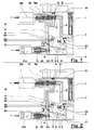
claim 1. Other aims, characteristics and advantages of the invention will be better understood by referring to the enclosed diagrams which represent two non- restrictive construction examples, in which: - Figs. 1 and 2 represent a partial cross-section of a first construction version of the invention in, respectively, a first and a second functioning condition.
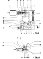
- Fig. 3 represents a partial cross-section of a second construction version of the example.
- Fig. 4 represent a partial cross-section, along the line N-N, of the carburator as in Fig. 3
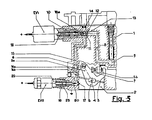
- Fig. 5 represent a partial cross-section of said first construction version, in a third functioning condition.
- With reference to Figs. 1, 2 and 5, a body of the carburator is indicated with 1 and comprises a
main barrel 2 which contains athrottle 3, rotating on ashaft 4 on which acontrol lever 5 is splined; anarm 5a of thelever 5 supports theaccelerator coupling 6; anarm 5b of thesame lever 5 abuts against aspeed adjusting screw 7, which defines the position of the throttle when the accelerator is released. - The idle system comprises a first channel 8 which begins at the base of the
well 9 and terminates in apipe 10 which houses an idle jet 11 that is positioned with a truncatedconical part 12 at the mouth of the channel 8; the jet 11 has ahole 13 which meters the fuel passing through it; the idle system also comprises: abush 14 which meters the emulsion air and achannel 15 which carries the emulsion to theprogression holes idle mixture hole 17. - The jet 11, internally hollow, houses an
obturator rod 18, integral with the movable keeper of a solenoid valve EVI. The cross-section of theidle mixture 17 is regulated by aconical point 20 of arod 19 integral with the movable keeper of a second solenoid valve EV2 the wrapping of which has a threadedpart 22 which is inserted in ahousing 23 in thecarburator body 1 near thehole 17, in a stable way, so as to regulate the flow of emulsion to a minimum when the solenoid valve EV2 is de-energised. - The solenoid valve EV2 moves the
rod 19 to extract thepoint 20 from thehole 17. - The bracket which supports the
screw 7 is electrically connected to an electronic control unit, not shown, to inform it as regards the position of themain lever 5 and thus of thethrottle 3; an electric closing signal is sent to the control unit when thearm 5b is in contact with thescrew 7. - We shall now describe the functions of the electronic control unit to give a better understanding of the invention. The power unit controls the solenoid valves EV, and EV2; if the engine speed is above of a first threshold R.P.M.1, memorised in said control unit as first electric value, then this sends a signal to solenoid valve EV, to keep the
obturator rod 18 towards the left, so that theball 18a keeps the section ofpassage 13 free; at the same time, it sends a control signal to the solenoid valve EV2 to keep thepoint 20 of therod 19 inserted in thehole 17, as can be seen in Fig. 1. When the accelerator is released, the control unit receives the said electric closing signal; since the engine speed is greater than R.P.M., the power unit controls the solenoid valve EV, to move therod 18 to close thehole 13 with theball 18a; at the same time, it controls the solenoid valve EV2 to move therod 19 leftwards in order to withdraw thepoint 20 from thehole 17; this condition is shown in fig. 2. In this way a value of vacuum near to those one existing in thebarrel 2 settles on the jet 11; if the driver opens thethrottle 3 slightly, the distance between thearm 5b and thescrew 7 warns the control unit that the accelerator is no longer released; this controls the solenoid valve EV, to open thehole 13, but maintains the solenoid valve EV2 as in fig. 2 to keep the vacuum signal quite high at the height of thehole 13 and to obtain an instantaneous filling of thechannel 15 of the idle system. The same functions are carried out by the control unit when the engine speed has fallen below a second threshold R.P.M.2«R.P.M., to obtain a correct engine speed. Below a predetermined engine speed value, the control unit resets the solenoid valves EV, and EV2 as shown in fig. 1. - The carburator shown in figs. 3 and 4 differs from that illustrated in figs. 1 and 2 as follows: the idling mixture adjusting screw is of the traditional type; the
progression chamber 26 is connected to acavity 28 by means of achannel 27; thecavity 28 leads to thecavity 30 through apassage 29; anotherchannel 31 leads from the saidcavity 30 and opens into themain barrel 2 by means of anopening 32 positioned below theidle mixture hole 17. Anobturator rod 35 is integral with the movable keeper of a solenoid valve EV3 thewrapping 33 of which is supported by means of screws in thecavity 28;sealing elements 34 are present to prevent the entry of air into thecavity 28. The obturator comprises aball 36, integral with therod 35 to close thepassage 29 under pressure of the closing forces of the solenoid valve EV3; in every other regard, the carburator shown in these figures comprises the same construction elements as that shown in figs. 1 and 2.
Claims (3)
Priority Applications (1)
| Application Number | Priority Date | Filing Date | Title |
|---|---|---|---|
| AT83830077T ATE31345T1 (en) | 1982-04-13 | 1983-04-07 | CARBURETTOR WITH ELECTROMAGNETIC DEVICES TO STOP THE FLOW OF FUEL WHEN THE ACCELERATOR PEDAL IS RELEASED. |
Applications Claiming Priority (2)
| Application Number | Priority Date | Filing Date | Title |
|---|---|---|---|
| IT339782 | 1982-04-13 | ||
| IT03397/82A IT1156584B (en) | 1982-04-13 | 1982-04-13 | CARBURETOR EQUIPPED WITH ELECTROMAGNETIC ACTION DEVICES, SUITABLE TO INTERRUPT THE FLOW OF THE FUEL DURING THE RELEASE PHASES |
Publications (2)
| Publication Number | Publication Date |
|---|---|
| EP0094918A1 EP0094918A1 (en) | 1983-11-23 |
| EP0094918B1 true EP0094918B1 (en) | 1987-12-09 |
Family
ID=11106349
Family Applications (1)
| Application Number | Title | Priority Date | Filing Date |
|---|---|---|---|
| EP83830077A Expired EP0094918B1 (en) | 1982-04-13 | 1983-04-07 | Carburetor fitted with electromagnetic devices for intercepting the flow of fuel during accelerator release |
Country Status (13)
| Country | Link |
|---|---|
| US (1) | US4498439A (en) |
| EP (1) | EP0094918B1 (en) |
| JP (1) | JPS58206855A (en) |
| AT (1) | ATE31345T1 (en) |
| BR (1) | BR8301894A (en) |
| CA (1) | CA1193927A (en) |
| DE (1) | DE3374888D1 (en) |
| ES (1) | ES521406A0 (en) |
| GR (1) | GR78173B (en) |
| IT (1) | IT1156584B (en) |
| PT (1) | PT76537B (en) |
| SU (1) | SU1246900A3 (en) |
| YU (1) | YU81383A (en) |
Families Citing this family (2)
| Publication number | Priority date | Publication date | Assignee | Title |
|---|---|---|---|---|
| JP4520893B2 (en) * | 2005-04-08 | 2010-08-11 | アイシン精機株式会社 | Engine mixer, engine-driven air conditioner, engine-driven power generator |
| RU2705350C1 (en) * | 2019-02-18 | 2019-11-06 | федеральное государственное бюджетное образовательное учреждение высшего образования "Пензенский государственный аграрный университет" | Automatic control system of carburetor engine operation in dynamic mode of independent idling |
Citations (1)
| Publication number | Priority date | Publication date | Assignee | Title |
|---|---|---|---|---|
| EP0089929A1 (en) * | 1982-03-17 | 1983-09-28 | WEBER S.r.l. | Carburetor fitted with a device for feeding the engine with lean mixture during accelerator release |
Family Cites Families (12)
| Publication number | Priority date | Publication date | Assignee | Title |
|---|---|---|---|---|
| FR1461577A (en) * | 1965-10-25 | 1966-02-25 | Sibe | Improvements in fuel supply devices for internal combustion engines |
| US3690305A (en) * | 1968-10-04 | 1972-09-12 | Hitachi Ltd | Fuel supply control system for automobile engines |
| US3996909A (en) * | 1975-02-21 | 1976-12-14 | General Motors Corporation | Fuel shut-off valve assembly |
| US3996908A (en) * | 1975-02-21 | 1976-12-14 | General Motors Corporation | Fuel shut-off valve assembly |
| US4146594A (en) * | 1975-07-10 | 1979-03-27 | Jean Raud | Fuel flow control device |
| JPS538431A (en) * | 1976-07-12 | 1978-01-25 | Hitachi Ltd | Air-to-fuel ratio control means for engine |
| JPS55148927A (en) * | 1979-05-09 | 1980-11-19 | Hitachi Ltd | Air-fuel ratio controller |
| JPS5650230A (en) * | 1979-09-28 | 1981-05-07 | Mitsubishi Motors Corp | Protecting apparatus for exhaust-gas purifying catalyst |
| JPS5675332A (en) * | 1979-11-26 | 1981-06-22 | Taihei Mach Works Ltd | Separating method for single veneer board and device therefor |
| JPS5678743A (en) * | 1979-11-28 | 1981-06-27 | Nec Corp | Device for adsorbing and separating thin film |
| JPS56107927A (en) * | 1980-01-31 | 1981-08-27 | Nissan Motor Co Ltd | Fuel feeder |
| DE3004199C2 (en) * | 1980-02-06 | 1984-12-06 | Dieter 4924 Barntrup Fialla | Device for shutting off the fuel supply in overrun mode of an internal combustion engine |
-
1982
- 1982-04-13 IT IT03397/82A patent/IT1156584B/en active
-
1983
- 1983-03-21 US US06/477,440 patent/US4498439A/en not_active Expired - Fee Related
- 1983-03-21 CA CA000424082A patent/CA1193927A/en not_active Expired
- 1983-04-06 GR GR71017A patent/GR78173B/el unknown
- 1983-04-07 EP EP83830077A patent/EP0094918B1/en not_active Expired
- 1983-04-07 YU YU00813/83A patent/YU81383A/en unknown
- 1983-04-07 DE DE8383830077T patent/DE3374888D1/en not_active Expired
- 1983-04-07 AT AT83830077T patent/ATE31345T1/en not_active IP Right Cessation
- 1983-04-11 BR BR8301894A patent/BR8301894A/en unknown
- 1983-04-12 PT PT76537A patent/PT76537B/en unknown
- 1983-04-12 ES ES521406A patent/ES521406A0/en active Granted
- 1983-04-12 SU SU833578256A patent/SU1246900A3/en active
- 1983-04-12 JP JP58064409A patent/JPS58206855A/en active Pending
Patent Citations (1)
| Publication number | Priority date | Publication date | Assignee | Title |
|---|---|---|---|---|
| EP0089929A1 (en) * | 1982-03-17 | 1983-09-28 | WEBER S.r.l. | Carburetor fitted with a device for feeding the engine with lean mixture during accelerator release |
Also Published As
| Publication number | Publication date |
|---|---|
| IT8203397A0 (en) | 1982-04-13 |
| DE3374888D1 (en) | 1988-01-21 |
| ES8403568A1 (en) | 1984-04-01 |
| PT76537B (en) | 1986-01-27 |
| PT76537A (en) | 1983-05-01 |
| EP0094918A1 (en) | 1983-11-23 |
| GR78173B (en) | 1984-09-26 |
| SU1246900A3 (en) | 1986-07-23 |
| US4498439A (en) | 1985-02-12 |
| ATE31345T1 (en) | 1987-12-15 |
| BR8301894A (en) | 1983-12-20 |
| JPS58206855A (en) | 1983-12-02 |
| IT1156584B (en) | 1987-02-04 |
| CA1193927A (en) | 1985-09-24 |
| YU81383A (en) | 1988-12-31 |
| ES521406A0 (en) | 1984-04-01 |
Similar Documents
| Publication | Publication Date | Title |
|---|---|---|
| US4453523A (en) | Pressure balanced flow regulator for gaseous fuel engine | |
| US2621911A (en) | Carburetor | |
| US3289659A (en) | Engine control device | |
| CA1046366A (en) | Control apparatus for diesel engine | |
| US3847131A (en) | Throttle operating mechanism for carburetor | |
| US3601106A (en) | Intake manifold vacuum control system | |
| US4089308A (en) | Carburation devices | |
| GB1476852A (en) | Electro-pneumatic device for regulating the supply of air to an internal combustion engine | |
| US4385604A (en) | Method and device for operation of an internal combustion engine in particular for a vehicle | |
| US3822687A (en) | Fuel feed device for gas-operated internal combustion engines | |
| US4137876A (en) | Opening device for the butterfly valve of a carburetor | |
| US4498439A (en) | Carburetor fitted with electromagnetic devices for intercepting the flow of fuel during accelerator release | |
| US3384059A (en) | Carburetion system with improved fuel-air ratio control system | |
| JPH04503389A (en) | Air supply system for internal combustion engines | |
| US4347817A (en) | Idle circuit shut-off valve | |
| EP0089929B1 (en) | Carburetor fitted with a device for feeding the engine with lean mixture during accelerator release | |
| US4290402A (en) | Gas-operated internal combustion engine | |
| US4124662A (en) | Carburetor and method of operating same | |
| GB2072753A (en) | Electrical control of carburettor throttle stop pneumatic actuators | |
| US3811418A (en) | Vehicle speed limiting device | |
| US4038819A (en) | Throttle opener | |
| US4630585A (en) | Carbureting device for an engine | |
| US3034492A (en) | Vacuum controlled gas saver | |
| US2705942A (en) | Compound carburetion system | |
| US2591272A (en) | Water injecting system for internal-combustion engines |
Legal Events
| Date | Code | Title | Description |
|---|---|---|---|
| PUAI | Public reference made under article 153(3) epc to a published international application that has entered the european phase |
Free format text: ORIGINAL CODE: 0009012 |
|
| AK | Designated contracting states |
Designated state(s): AT BE CH DE FR GB LI LU NL SE |
|
| RAP1 | Party data changed (applicant data changed or rights of an application transferred) |
Owner name: WEBER S.P.A. |
|
| 17P | Request for examination filed |
Effective date: 19840517 |
|
| RAP1 | Party data changed (applicant data changed or rights of an application transferred) |
Owner name: WEBER S.R.L. |
|
| GRAA | (expected) grant |
Free format text: ORIGINAL CODE: 0009210 |
|
| AK | Designated contracting states |
Kind code of ref document: B1 Designated state(s): AT BE CH DE FR GB LI LU NL SE |
|
| REF | Corresponds to: |
Ref document number: 31345 Country of ref document: AT Date of ref document: 19871215 Kind code of ref document: T |
|
| REF | Corresponds to: |
Ref document number: 3374888 Country of ref document: DE Date of ref document: 19880121 |
|
| PG25 | Lapsed in a contracting state [announced via postgrant information from national office to epo] |
Ref country code: AT Effective date: 19880407 |
|
| ET | Fr: translation filed | ||
| PG25 | Lapsed in a contracting state [announced via postgrant information from national office to epo] |
Ref country code: LU Free format text: LAPSE BECAUSE OF NON-PAYMENT OF DUE FEES Effective date: 19880430 |
|
| PLBE | No opposition filed within time limit |
Free format text: ORIGINAL CODE: 0009261 |
|
| STAA | Information on the status of an ep patent application or granted ep patent |
Free format text: STATUS: NO OPPOSITION FILED WITHIN TIME LIMIT |
|
| BERE | Be: lapsed |
Owner name: WEBER S.R.L. Effective date: 19880430 |
|
| PG25 | Lapsed in a contracting state [announced via postgrant information from national office to epo] |
Ref country code: NL Effective date: 19881101 |
|
| 26N | No opposition filed | ||
| NLV4 | Nl: lapsed or anulled due to non-payment of the annual fee | ||
| PGFP | Annual fee paid to national office [announced via postgrant information from national office to epo] |
Ref country code: SE Payment date: 19890329 Year of fee payment: 7 |
|
| PGFP | Annual fee paid to national office [announced via postgrant information from national office to epo] |
Ref country code: GB Payment date: 19890331 Year of fee payment: 7 |
|
| PGFP | Annual fee paid to national office [announced via postgrant information from national office to epo] |
Ref country code: DE Payment date: 19890414 Year of fee payment: 7 |
|
| PG25 | Lapsed in a contracting state [announced via postgrant information from national office to epo] |
Ref country code: LI Effective date: 19890430 Ref country code: CH Effective date: 19890430 Ref country code: BE Effective date: 19890430 |
|
| PGFP | Annual fee paid to national office [announced via postgrant information from national office to epo] |
Ref country code: FR Payment date: 19890531 Year of fee payment: 7 |
|
| REG | Reference to a national code |
Ref country code: CH Ref legal event code: PL |
|
| PG25 | Lapsed in a contracting state [announced via postgrant information from national office to epo] |
Ref country code: GB Effective date: 19900407 |
|
| PG25 | Lapsed in a contracting state [announced via postgrant information from national office to epo] |
Ref country code: SE Effective date: 19900408 |
|
| GBPC | Gb: european patent ceased through non-payment of renewal fee | ||
| PG25 | Lapsed in a contracting state [announced via postgrant information from national office to epo] |
Ref country code: FR Effective date: 19901228 |
|
| PG25 | Lapsed in a contracting state [announced via postgrant information from national office to epo] |
Ref country code: DE Effective date: 19910101 |
|
| REG | Reference to a national code |
Ref country code: FR Ref legal event code: ST |
|
| EUG | Se: european patent has lapsed |
Ref document number: 83830077.0 Effective date: 19910115 |