EP0093213A1 - Electrolytes circulation type cell stack secondary battery - Google Patents
Electrolytes circulation type cell stack secondary battery Download PDFInfo
- Publication number
- EP0093213A1 EP0093213A1 EP82302273A EP82302273A EP0093213A1 EP 0093213 A1 EP0093213 A1 EP 0093213A1 EP 82302273 A EP82302273 A EP 82302273A EP 82302273 A EP82302273 A EP 82302273A EP 0093213 A1 EP0093213 A1 EP 0093213A1
- Authority
- EP
- European Patent Office
- Prior art keywords
- anolyte
- battery
- catholyte
- potential
- cell stack
- Prior art date
- Legal status (The legal status is an assumption and is not a legal conclusion. Google has not performed a legal analysis and makes no representation as to the accuracy of the status listed.)
- Granted
Links
- 239000003792 electrolyte Substances 0.000 title abstract description 32
- 230000005540 biological transmission Effects 0.000 claims description 6
- 238000010276 construction Methods 0.000 claims 2
- 238000004070 electrodeposition Methods 0.000 abstract description 26
- 230000002159 abnormal effect Effects 0.000 abstract description 15
- 239000011149 active material Substances 0.000 abstract description 2
- 230000005611 electricity Effects 0.000 description 18
- 230000001681 protective effect Effects 0.000 description 18
- 239000011701 zinc Substances 0.000 description 13
- VNDYJBBGRKZCSX-UHFFFAOYSA-L zinc bromide Chemical class Br[Zn]Br VNDYJBBGRKZCSX-UHFFFAOYSA-L 0.000 description 13
- 238000000034 method Methods 0.000 description 9
- HCHKCACWOHOZIP-UHFFFAOYSA-N Zinc Chemical compound [Zn] HCHKCACWOHOZIP-UHFFFAOYSA-N 0.000 description 8
- 238000009826 distribution Methods 0.000 description 8
- 229910052725 zinc Inorganic materials 0.000 description 8
- 230000007812 deficiency Effects 0.000 description 7
- 238000010586 diagram Methods 0.000 description 7
- 238000012360 testing method Methods 0.000 description 7
- 239000007788 liquid Substances 0.000 description 6
- 238000005259 measurement Methods 0.000 description 6
- 230000000694 effects Effects 0.000 description 5
- 230000003247 decreasing effect Effects 0.000 description 4
- 238000013461 design Methods 0.000 description 3
- 238000007599 discharging Methods 0.000 description 3
- 150000002500 ions Chemical class 0.000 description 3
- 229940102001 zinc bromide Drugs 0.000 description 3
- GDTBXPJZTBHREO-UHFFFAOYSA-N bromine Substances BrBr GDTBXPJZTBHREO-UHFFFAOYSA-N 0.000 description 2
- 238000012423 maintenance Methods 0.000 description 2
- 238000012986 modification Methods 0.000 description 2
- 230000004048 modification Effects 0.000 description 2
- WKBOTKDWSSQWDR-UHFFFAOYSA-N Bromine atom Chemical compound [Br] WKBOTKDWSSQWDR-UHFFFAOYSA-N 0.000 description 1
- 230000006399 behavior Effects 0.000 description 1
- 229910052794 bromium Inorganic materials 0.000 description 1
- -1 cadmiun Substances 0.000 description 1
- 239000012530 fluid Substances 0.000 description 1
- 229910052751 metal Inorganic materials 0.000 description 1
- 239000002184 metal Substances 0.000 description 1
- 238000011160 research Methods 0.000 description 1
- 230000001502 supplementing effect Effects 0.000 description 1
Images


Classifications
-
- H—ELECTRICITY
- H01—ELECTRIC ELEMENTS
- H01M—PROCESSES OR MEANS, e.g. BATTERIES, FOR THE DIRECT CONVERSION OF CHEMICAL ENERGY INTO ELECTRICAL ENERGY
- H01M10/00—Secondary cells; Manufacture thereof
- H01M10/42—Methods or arrangements for servicing or maintenance of secondary cells or secondary half-cells
- H01M10/4214—Arrangements for moving electrodes or electrolyte
-
- H—ELECTRICITY
- H01—ELECTRIC ELEMENTS
- H01M—PROCESSES OR MEANS, e.g. BATTERIES, FOR THE DIRECT CONVERSION OF CHEMICAL ENERGY INTO ELECTRICAL ENERGY
- H01M50/00—Constructional details or processes of manufacture of the non-active parts of electrochemical cells other than fuel cells, e.g. hybrid cells
- H01M50/70—Arrangements for stirring or circulating the electrolyte
- H01M50/77—Arrangements for stirring or circulating the electrolyte with external circulating path
-
- Y—GENERAL TAGGING OF NEW TECHNOLOGICAL DEVELOPMENTS; GENERAL TAGGING OF CROSS-SECTIONAL TECHNOLOGIES SPANNING OVER SEVERAL SECTIONS OF THE IPC; TECHNICAL SUBJECTS COVERED BY FORMER USPC CROSS-REFERENCE ART COLLECTIONS [XRACs] AND DIGESTS
- Y02—TECHNOLOGIES OR APPLICATIONS FOR MITIGATION OR ADAPTATION AGAINST CLIMATE CHANGE
- Y02E—REDUCTION OF GREENHOUSE GAS [GHG] EMISSIONS, RELATED TO ENERGY GENERATION, TRANSMISSION OR DISTRIBUTION
- Y02E60/00—Enabling technologies; Technologies with a potential or indirect contribution to GHG emissions mitigation
- Y02E60/10—Energy storage using batteries
Definitions
- the present invention relates to electrolytes circulation type cell stack secondary batteries, particularly those in which the negatively active material is a metal such as cadmiun, zinc or lead, and more particularly the invention relates to such secondary battery which suppresses and prevents the occurrence of three problems due to the flow of small shunt current, i. e., (1) shunt current loss, (2) unequality of quantity of charged electricity and (3) occurrence of abnormal electrodeposition.
- small shunt current i. e., (1) shunt current loss, (2) unequality of quantity of charged electricity and (3) occurrence of abnormal electrodeposition.
- Known cell stack batteries of the above type are designed so that generally, with a view to producing a high voltage from practical point view, a plurality of secondary cells are arranged in layers and connected in series such that each of the electrolytes is supplied to the cathode chamber or the anode chamber of each secondary cell via its catholyte inlet channel or anolyte inlet channel from a catholyte inlet-side common manifold or an anolyte inlet-side common manifold and the electrolyte is delivered via the catholyte outlet channel or the anolyte outlet channel of each secondary cell and through a catholyte outlet-side common manifold or an anolyte outlet-side common manifold.
- the manifolds and the channels are decreased in diameter and increased in length so as to increase the electric resistance of the electrolytes in the manifolds and the channels and thereby to decrease the shunt current value.
- the present invention has been made as a result of various studies and research works made with a view to overcoming the foregoing deficiencies in the prior art, and it is the primary object of the invention to provide an improved electrolytes circulation type cell stack secondary battery capable of preventing the occurrence of abnormal electrodeposition, eliminating the unequality of quantity of charged electricity and reducing the amount of shunt current loss.
- Fig. 1 shows an embodiment of this invention in which the adjoining catholyte channels of low-potential-side secondary cells of a cell stack secondary battery are interconnected with small diameter pipes and additional electrodes are arranged in the vicinity of the junctions between the pipe and the channels of the lowest-voltage secondary cell so as to be connected to and held at the same potential as the cathode terminal of the cell stack secondary battery.
- numerals 1, 2, 3 ??, 10 designate secondary cells and the illustrated embodiment includes ten secondary cells arranged in layers.
- the description will now be made mainly with reference to the secondary cell 1.
- Numeral 11 designates a cathode, 12 an anode, and 13 an ion transmission separator arranged practically midway between the electrodes 11 and 12.
- Numeral 14 and 15 designate electrode frames.
- Numeral 16 designates a cathode chamber, 17 an anode chamber, and 18 a cathode terminal of the secondary cell 1.
- the anode 12 of the cell 1 is connected to a cathode 20 of the adjoining secondary cell 2 by a connector 19.
- a connector 19 Of course, where it is desired to provide a bipolar type cell stack battery, it is only necessary to arrange in layers only one or the other of the anode 11 and the cathode 12 which have the same potential.
- Numeral 21 designates a catholyte inlet-side common manifold, 25, 26, 27, 28, .... catholyte inlet channels for connecting the catholyte inlet-side common manifold 21 to the cathode chambers 16, 41, 43, 45, whereas
- Numeral 22 designates a catholyte outlet-side common manifold, and 33, 34, 35, 36 ... catholyte outlet channels for connecting the catholyte outlet-side common manifold 22 to the cathode chambers 16, 41, 43, 45, ....
- numeral 23 designates an anolyte inlet-side common manifold, 24 an anolyte outlet-side common manifold, 29, 30, 31, 32, ...
- electrolyte inlet channels and 37, 38, 39, 40, ... anolyte outlet channels.
- electrolyte inlet channels 25, 26, 27, 28, ... and 29, 30, 31, 32 ... and the electrolyte outlet channels 33, 34, 35, 36, ... and 37, 38, 39, 40 ... are extended perpendicular to the layer-building direction of the electrode frames 14 and 15 and arranged side by side along the electrode frames 14 and 15.
- the cell stack secondary battery constructed as described above is the same with the prior art battery so that the catholyte is fed into the cathode chambers 16, 41, ... of the secondary cells, 1, 2, ... by a pump (not shown) by way of the catholyte inlet-side common manifold 21 and the electrolyte inlet channels 25, 26, ..., and the electrolyte is delivered to the outlet-side common manifold 22 by way of the electrolyte outlet channels 33, 34, ....
- the anolyte is introduced into the anode chambers 17, 42, ..., of the secondary cells 1, 2, ..., by a pump (not shown) from the anolyte inlet-side common manifold 23 via the electrolyte inlet channels 29, 30, ..., and the electrolyte is delivered to the anolyte outlet-side common manifold 24 via the anolyte outlet channels 33, 34, ...
- the cell stack secondary battery constructed as described above is further provided with small-diameter pipes 59, 60, 61 and 62, 63, 64 which respectively interconnect the adjoining ones of the low- voltage-side catholyte channels 25, 26, 27, 28 and 33, 34, 35, 36 of the secondary cells 1, 2, 3, 4, .... Since these pipes 59, 60, ..., 64 are not intended to flow the catholyte therethrough, it is only necessary that these pipes are filled with the catholyte to simply connect the adjoining channels electrically and thus they can be extremely small in diameter.
- a shunt current also flows to the pipes.
- the pipes should be as small as possible in diameter and hence electric resistance within the pipes should be as high as possible.
- electrodes 65 and 66 are respectively arranged in the vicinity of the junctions between the pipes 59 and 62 of the catholyte channels 25 and 33 of the secondary cell 1 having the lowest voltage and the electrodes 65 and 66 are connected to the cathode terminal 18 of the cell stack secondary battery by a connector 67 to maintain them at the same potential as the cathode 11.
- the electrodes 65 and 66 may be mounted by for example fitting them into the catholyte channels 25 and 33, respectively, and hermetically fixing them in place.
- Fig. 2 shows characteristic diagrams showing the results of the shunt current measurement during the charging period of the cell stack secondary batteries.
- marks "A” show the results of the prior art cell stack battery and spot marks show the results of the cell stack battery according to the invention.
- (a) shows the measurement results at the catholyte inlets, and (b) shows the measurement results at the catholyte outlets.
- the ordinate represents the shunt current value (mA) and the abscissa represents the channel positions of the respective secondary cells.
- the value of the shunt current flowing out of each cathode chamber is designated as positive.
- Fig. 3 shows another embodiment of the present invention which differs from the first embodiment in that the catholyte manifolds 21 and 22 of the cell stack secondary battery are respectively connected to the anolyte manifolds 23 and 24 by channels 70 and 71 by way of ion transmission separators 68 and 69 and additional electrodes 72 and 73 arranged at positions where they are immersed in the anolyte and are connected to the cathode 11 of the secondary cell 1, thereby absorbing any small shunt current.
- the transmission separators 68 and 69 transmit ions but they do not transmit the electrolytes.
- the electrodes 72 and 73 may respectively be fitted into the anolyte manifolds 23 and 24.
- connecting channels 70 and 71 may be interconnected by a bypass pipe 74 so that they are interconnected on the anolyte side.
- the anolyte is circulated so as to satisfactorily supply the bromine in the electrolyte to the additional electrodes 72 and 73.
- the electrodes 72 and 73 are immersed in the anolyte so that a reaction of Br 2 ⁇ 2Br -2e occurs and no electrodeposition of Zn takes place, thus maintaining the electrode surfaces in the initial condition. As a result, no maintenance is required for the electrodes 72 and 73 over a long period of service. Then,in the respective secondary cells 1, 2, unlike , a reaction of Zn ++ + 2e ⁇ Zn occurs in the cathode chambers 16, 41, ... and a reaction of 2Br24Br2 + 2e occurs in the anode chambers 17, 42, .... , thus delivering a desired voltage across the cathode terminal 18 and an anode terminal 75.
- Fig. 5 shows characteristic diagrams showing by way of examples the results of shunt current measurements during the charging period of the battery shown in Fig. 3, with (A) showing the shunt current values mA at the catholyte inlets, (B) those at the anolyte inlets, (C) those at the catholyte outlets and (D) those at the anolyte outlets.
- the positive shunt current values represent the shunt currents flowing out to the manifolds from the cathode and the negative values represent those flowing into the cathode.
- the abscissa represents the channel positions of the respective secondary cells (here the number of the cell stack secondary cells is 5).
- (a) shows the prior art battery (without the electrodes 72 and 73)
- (b) shows the most simplified form of cell stack secondary battery, i.e., the battery of Fig. 1 without the pipes 59, 60, ... 63, 64
- (c) shows the cell stack secondary battery of Fig. 3 in comparison with one another.
- the shunt current values of the respective channels indicate those measured by a clip-on ammeter.
- the charging voltage was 11.3 V
- the charging current was 12 A and the current values were those measured at the expiration of 90 to 110 minutes after the beginning of the charging.
- a cell stack secondary battery which eliminates the flow of shunt current to the cathode, thereby eliminating the occurrence of abnormal electrodeposition in the vicinity of the cathode ends and also eliminating the need for maintenance over a long period of service.
- Fig. 7 shows still another embodiment in the form of a zinc bromide system five-layer cell stack secondary battery.
- electrodes 65 and 66 are fitted respectively into catholyte manifolds 21 and 22 and their potentials are adjusted by an auxiliary power supply 7b to a value lower than the potential shown by a cathode 11 of a secondary cell 1, thereby preventing any shunt current occurring in the catholyte circulation system from flowing into cathode chambers 16, 41, 43, ... of the respective secondary cells from the catholyte manifolds 21 and 22.
- electrodes 77 and.78 are respectively fitted into anolyte manifolds 23 and 24 and the potential of these additional electrodes is held by an auxiliary power supply 79 higher than the potential shown by an anode 12 of a secondary cell 5, thereby allowing any shunt current caused in the anolyte circulation system to flow into anode chambers 17, 42, 44, ... of the respective secondary cells.
- FIG. 6 shows a longitudinal sectional view of a secondary cell and (b) shows the corresponding resistance equivalent circuit.
- numeral 80 designates an anode, 81 a cathode, Va an anode potential, Vc a cathode potential, and Va + Vc an open-circuit potential of the secondary cell.
- Rc is a electric resistance of a catholyte channel liquid Ra an electric resistance of an anolyte channel liquid (the same value is assumed for the outlet and inlet in both cases), and Re a secondary cell internal electric resistance.
- Fig. 8 shows a resistance equivalent circuit of the five-layer cell stack battery of Fig. 7.
- Fig. 8 is constructed on the basis of the quivalent circuit shown in Fig. 6. If the channels and manifolds on the outlet and inlet sides of the electrolyte circulation paths are respectively selected equal in size, the resistance equivalent circuit can be represented for example on the inlet sides of the electrolyte circulation paths as shown in Fig. 8.
- the electrode potentials are replaced with the open-circuit voltage.
- Fig. 7 shows by way of example the five-layer cell stack zinc bromide battery constructed in accordance with the above-mentioned design.
- the channels each has a diameter and length corresponding to the previously mentioned design resistance value.
- the corresponding relations between the channels and the resistances are as follows: Rc 1 ⁇ 25, 33 , Rc 2 ⁇ 26, 34, Rc 3 ⁇ 27, 35, ... , Ra 1 ⁇ 29, 37, Ra2 ⁇ 30, 38, Ra 3 ⁇ 31, 39, ... , etc.
- the electrodes 65 and 66 are respectively fitted into the catholyte common manifolds 21 and 22 and the electrodes 77 and 78 are respectively fitted into the anode common manifolds 23 and 24. These electrodes are hermetically fixed in place.
- the electrodes 65 and 66 are connected to the negative terminal of the auxiliary power supply 76 whose positive terminal is connected to a cathode terminal 18 of the cell stack secondary battery.
- the electrodes 77 and 78 are connected to the positive terminal of the auxiliary power supply 79 whose negative terminal is connected to an anode terminal 75 of the cell stack secondary battery.
- Fig. 9 shows the measurements of the values of the shunt currents which were supplied to the respective channels when ten cycles of three patterns, i.e., charge, open-circuit and discharge were performed in the five-layer zinc bromide secondary battery.
- the abscissa represents the numbers of the secondary cell cathode in order of increasing voltage and the ordinate represents the corresponding measured values.
- marks of "0" indicate the measured values obtained in accordance with the invention and marks of "1" indicate those obtained without the application of the invention, that is, those obtained by replacing the channel portions of the respective cells with the conventional ones to make the cells equal in channel electric resistance (all the channel electric resistances ⁇ 1500 n ).
- FIG. 9 shows cathode current distribution diagrams showing the values of the currents through the cathode of the respective cells whichwere obtained from the shunt current values obtained in the above-mentioned manner and which were shown in terms of the value of the current through the lowest voltage cathode as a zero point. If the time factor is involved in the current values, these diagrams show charged electricity quantity distributions in terms of mA.Hr.
- FIG. 9 (a) shows the distribution for charging condition, (b) the distribution for open-circuit condition (c) the distribution for discharging condition.
- the results of the calculations made from the measured shunt current values and the electrolyte electric resistance values in the manifolds and the channels showed that in the case using the invention the loss was 0.48 W showing only a slight increase over 0.14 W of the case without the application of the invention.
- the required protective current was about 32 mA and the calculated value of the loss due to the protective current was estimated to amount to 3.6 W.
- the electrodes 65, 66 and 77, 78 are respectively fitted into the catholyte manifolds 21 and 22 and the anolyte manifolds 23 and 24, it is possible to fit the electrodes 65 and 66 into the catholyte channels 25 and 33, respectively, and fit the electrodes 77 and 78 into the corresponding anolyte inlet and outlet channels.
- the present invention comprises the following solutions for providing improvements relating to the deficiencies due to shunt current, i.e., the occurrence of abnormal elec - trodeposition, unequality of quantity of charged electricity and shunt current loss.
- shunt currents flow out to the anolyte manifolds from the anode chambers and shunt currents are introduced from the anolyte manifolds into the anode chambers on the low voltage side.
- the potential of the electrodes fitted into the catholyte manifolds is adjusted by the auxiliary power supply in such a manner that in the secondary cells on the low voltage side the value of a shunt current flowing out of the catholyte chamber becomes higher than that of a shunt current flowing into the anode chamber.
- any unequality of quantity of charged electricity is caused by the fact that the sum total of the shunt currents flowing in and out through the channels is not zero in each of the secondary cells of the cell stack secondary battery except the highest voltage cell.
- additional channels and an additional manifold are provided to connect the anode chambers of the secondary cells to each other and an additional electrode is fitted into the additional channel or the additional manifold and connected to the positive terminal of the cell stack secondary battery through an auxiliary power supply.
- the internal electrolyte electric resistances of the channels and the manifold are adjusted in such a manner that a current for supplementing the small currents flowing out of the secondary cells is supplied into the anode chambers through the channels and the manifold interconnecting these chambers and thus the small currents flowing in and out are reduced to zero on the whole in each of the secondary cells of the cell stack secondary battery except the highest voltage cell, thereby overcoming the problem of unequality of quantity of charged electricity.
- Fig. 10 is a longitudinal sectional view showing a three- layer cell stack secondary battery with shunt current protective means according to another embodiment of the invention, in which additional channels 82, 83 and 84 and an additional manifold 85 are connected to the respective anode chambers 17, 42 and 44.
- An additional electrode 86 is fitted into the manifold 85 and is hermetically fixed in place. The electrode 86 is connected by means of a connecting member 87 to the auxiliary power supply 79 connected to the positive terminal 75.
- Fig. 11 illustrates a resistance equivalent circuit corresponding to the three-layer cell stack secondary battery of Fig. 10, and the symbols in the Figure denote as follows:
- the electrodes 65 and 66 are respectively fitted into the catholyte manifolds (21 and 22 in Fig. 10) of the cell stack secondary battery of Fig. 10 without the manifold 85 and the channels 82, 83 and 84 and the potential of the electrodes 65 and 66 is maintained by the auxiliary power supply 76 lower than the cathode terminal of the cell stack secondary battery. Then the battery is operated with the following charging conditions.
- the values of the shunt currents flowing through the electrolyte circulation channels are measured with a clip-on ammeter and then the sum totals of the shunt currents flowing out of the respective secondary cells are obtained as follows: .
- the following values are set then, the following are obtained from the equations (54) to (56)
- the sizes of the channels and the manifold are adjusted and then the three-layer ZnBr 2 cell stack secondary battery is operated.
- Fig. 12 shows the test results of the present embodiment.
- the values of currents through the cathode of the three-layer battery were measured by converting the currents through the respective channels and the current through the cathode (11 in Fig. 10) of the secondary cell having the lowest voltage among the cells of the three- layers of the secondary battery is selected as a zero point, thereby comparing the currents through the respective cathode and showing the resulting distribution of the quantities of charged electricity in the respective secondary cells.
- the ordinate represents the cathode current and the abscissa represents the secondary cell cathode.
- Marked "e” is the case where the electrodes 65, 66 were not fitted in the cathode manifolds 21 and 22 and the manifold 85 and the channels 82, 83 and 84 were not provided in Fig. 10.
- Marked " ⁇ " is the case where the electrodes 65 and 66 were fitted into the cathode manifolds 21 and 22 and the potential of the auxiliary power supply 76 was lower by 2 V than the cathode terminal of the cell stack secondary battery.
- Marked "O" is the case where the manifold 85 and the channels 82, 83 and 84 were provided in addition to the electrodes 65 and 66 and the potential of the electrode 86 was higher by 2 V than the anode terminal of the cell stack secondary battery.
- the loss due to the protective current was estimated on the basis of the currents through the channels and the manifolds and the internal electrolyte electric resistances of the manifolds .and the channels and the results showed that in the case using the invention (marked “O” in Fig. 12) the loss was 208 mW and this was greater than 56 mW obtained in the case without the application of the invention (marked "0" in Fig. 12).
- the protective current according to U.S.P. No. 4,197,169 was applied to. the known type of battery without using the invention, the required protective current was 364 mA and the calculated value of the lose due the protective current was estimated to amount to 2,200 m.W.
- a cell stack secondary battery which reduces the loss due to the protective current, reduces the deficiencies due to the flow of shunt current and increases the cycle life.
- the cathode 65 and 66 may be connected directly to the cathode terminal of the cell stack secondary battery.
- Fig. 13 is a longitudinal sectional view showing a cell stack secondary battery with shunt current protective means according to still another embodiment of the invention.
- the catholyte manifolds 21 and 22 are respectively connected to the anolyte manifolds 23 and 24 by pipes 70 and 71, respectively, and separators 68 and 69 are respectively firmly held in position in the pipes 70 and 71 to prevent the anolyte and catholyte from mixing together. While, in the embodiment of Fig.
- the electrodes 65 and 66 are fitted into the catholyte manifolds 21 and 22, in the present embodiment electrodes 72 and 73 are respectively fitted into the pipes 70 and 71 and immersed into the anolyte divided by the separators 68 and 69.
- the electrodes 72 and 73 are connected to the terminal 18 by a connector 55 and are held at the same potential as the cathode 11 of the secondary cell 1.
- the electrodes 72 and 73 and the cathode 11 of the secondary cell 1 form a cell since the electrodes 72 and 73 are positioned in the anolyte and the cathode 11 is in the catholyte on the other side of the separators 68 and 69, respectively.
- the electrodes 72 and 73 are positioned in the anolyte to produce an electrochemical potential difference and thereby to provide the equivalent function with the auxiliary power supply 76.
- the cell stack secondary battery of this embodiment functions practically in the same manner as the embodiment of Fig. 10.
- the present embodiment may include the auxiliary power supply 76 so as to adjust the potential of the electrodes 72 and 73 as desired.
- Fig. 14 is a longitudinal sectional view showing a cell stack secondary battery with shunt current protective means according to still another embodiment of the invention. This embodiment differs from the embodiment of Fig. 13 in that the electrode 86 fitted into the manifold 85 is eliminated and its function is served by the anode 12 of the secondary cell 3.
- the current (i 1 + i 2 + i3) is supplied from the electrode 86 on the basis of the following assumption.
- the electrode 86 into the manifold 85 and connect it to the anode 12 as shown by the phantom line in Fig. 14 so as to apply a potential thereto.
- the auxiliary power supplies it is possible to set the anode and cathode terminal side manifold potentials to any desired low or high values and thus it is possible to reduce the channel and manifold electric resistance losses required for attaining the condition for realizing the invention, that is, the condition that the current flowing out of the cathode chamber is equal to the current flowing out of the anode chamber.
- the cell stack secondary battery with shunt current protective means has the effect of making the current flowing out of the cathode chamber equal to the current flowing out of the anode chamber and thereby eliminating the occurrence of abnormal electrodeposition and the unequality of quantity of charged electricity and reducing the shunt current loss.
- the invention can be said to be very useful in practical applications.
Landscapes
- Chemical & Material Sciences (AREA)
- Chemical Kinetics & Catalysis (AREA)
- Electrochemistry (AREA)
- General Chemical & Material Sciences (AREA)
- Engineering & Computer Science (AREA)
- Manufacturing & Machinery (AREA)
- Hybrid Cells (AREA)
Abstract
Description
- The present invention relates to electrolytes circulation type cell stack secondary batteries, particularly those in which the negatively active material is a metal such as cadmiun, zinc or lead, and more particularly the invention relates to such secondary battery which suppresses and prevents the occurrence of three problems due to the flow of small shunt current, i. e., (1) shunt current loss, (2) unequality of quantity of charged electricity and (3) occurrence of abnormal electrodeposition.
- Known cell stack batteries of the above type are designed so that generally, with a view to producing a high voltage from practical point view, a plurality of secondary cells are arranged in layers and connected in series such that each of the electrolytes is supplied to the cathode chamber or the anode chamber of each secondary cell via its catholyte inlet channel or anolyte inlet channel from a catholyte inlet-side common manifold or an anolyte inlet-side common manifold and the electrolyte is delivered via the catholyte outlet channel or the anolyte outlet channel of each secondary cell and through a catholyte outlet-side common manifold or an anolyte outlet-side common manifold.
- Thus, since the plurality of secondary cells are connected in series and the circulation of the electrolytes is effected in a parallel connection manner, a small current is diverted to each of the inlet and outlet sides of each secondary cell due to the potential difference between the low potential side electrode and the high potential side electrode of the plurality of series connected cells, thus giving rise to the following difficulties.
- (1) Shunt current loss: The loss of heat in the manifolds and the channels due to the flow of small shunt currents.
- (2) Unequality of quantity of charged electricity: Since the current value (mA) of small shunt current flow through the channels of the respective cells differs from one cell to another, the value of current flow through the electrodes of the respective cells differs from one cell to another with the resulting unequality of the electrodeposition on the cathode or the quantity of charged electricity.
- (3) Occurrence of abnormal electrodeposition: At the low potential side cathode ends to which a small current flows even a small shunt current may result in the occurrence of abnormal electrodeposition due to the current concentration.
- Many different proposals have heretofore been made to overcome such deficiencies due to the flow of small shunt current. For instance, the manifolds and the channels are decreased in diameter and increased in length so as to increase the electric resistance of the electrolytes in the manifolds and the channels and thereby to decrease the shunt current value. While this known method has the effect of providing improvements on some of the foregoing deficiencies due to the flow of shunt current, i.e., the shunt current loss and the unequality of quantity of charged electricity, even if the shunt current is decreased, the shunt current flows in the same direction during the charging period as well as the discharging period with the result that abnormal electrodeposition is caused as the cycle of charge and discharge is repeated, thus impeding the circulation of the electrolytes and causing a short-circuit between the secondary cells and thereby giving a limitation to the cycle life.
- Another method has been proposed (U.S.P. 4,197,169) in which a protective current is supplied to the manifolds so that the potential distribution in the manifolds is made equal to the potential distribution in the respective secondary cells thereby overcoming the deficiencies due to the flow of shunt current. While this method prevents the occurrence of shunt current with the resulting solution of the foregoing problems due to the flow of shunt current, the supply of the additional protective current produces an additional energy loss. While this energy loss can be reduced to some extent by decreasing the diameter of the manifolds, there is a limit to the decrease in the manifold diameter since this gives rise to ununiformness in the circulation of the electrolytes to the secondary cells and increase in the fluid head loss for the circulation pumps and thus this prior art method still has the problem of energy loss due to the protective current.
- The present invention has been made as a result of various studies and research works made with a view to overcoming the foregoing deficiencies in the prior art, and it is the primary object of the invention to provide an improved electrolytes circulation type cell stack secondary battery capable of preventing the occurrence of abnormal electrodeposition, eliminating the unequality of quantity of charged electricity and reducing the amount of shunt current loss.
-
- Figs. 1, 3, 4, 6(a), 7, 10, 13 and 14 show model longitudinal sectional views of cell stack secondary batteries according to specific embodiments of the invention.
- Figs. 2, 5, 9 and 12 show the behaviours of the batteries during the charging period.
- Figs. 6(b), 8 and 11 are diagrams showing resistance equivalent circuits for the cell stack secondary batteries.
- The present invention will now be described in greater detail with reference to the illustrated embodiments.
- Fig. 1 shows an embodiment of this invention in which the adjoining catholyte channels of low-potential-side secondary cells of a cell stack secondary battery are interconnected with small diameter pipes and additional electrodes are arranged in the vicinity of the junctions between the pipe and the channels of the lowest-voltage secondary cell so as to be connected to and held at the same potential as the cathode terminal of the cell stack secondary battery. By so constructing, it is intended to absorb by these additional electrodes any small current flowing to each cell and thereby to prevent the occurrence of abnormal electrodeposition due to the flow of small shunt current, thus increasing the service life of the battery when it is used in cycles. This embodiment will now be described with reference to the Figure.
- In the Figure,
numerals secondary cell 1. Numeral 11 designates a cathode, 12 an anode, and 13 an ion transmission separator arranged practically midway between theelectrodes 11 and 12. Numeral 14 and 15 designate electrode frames. Numeral 16 designates a cathode chamber, 17 an anode chamber, and 18 a cathode terminal of thesecondary cell 1. Theanode 12 of thecell 1 is connected to acathode 20 of the adjoiningsecondary cell 2 by aconnector 19. Of course, where it is desired to provide a bipolar type cell stack battery, it is only necessary to arrange in layers only one or the other of the anode 11 and thecathode 12 which have the same potential. - Numeral 21 designates a catholyte inlet-side common manifold, 25, 26, 27, 28, .... catholyte inlet channels for connecting the catholyte inlet-side
common manifold 21 to thecathode chambers common manifold 22 to thecathode chambers numeral 23 designates an anolyte inlet-side common manifold, 24 an anolyte outlet-side common manifold, 29, 30, 31, 32, ... anolyte inlet channels, and 37, 38, 39, 40, ... anolyte outlet channels. Theseelectrolyte inlet channels electrolyte outlet channels electrode frames electrode frames - The cell stack secondary battery constructed as described above is the same with the prior art battery so that the catholyte is fed into the
cathode chambers common manifold 21 and theelectrolyte inlet channels common manifold 22 by way of theelectrolyte outlet channels anode chambers secondary cells common manifold 23 via theelectrolyte inlet channels common manifold 24 via theanolyte outlet channels - In accordance with the invention, the cell stack secondary battery constructed as described above is further provided with small-
diameter pipes side catholyte channels secondary cells pipes 59, 60, ..., 64 are not intended to flow the catholyte therethrough, it is only necessary that these pipes are filled with the catholyte to simply connect the adjoining channels electrically and thus they can be extremely small in diameter. When the cell stack secondary battery is in operation, a shunt current also flows to the pipes. Thus, in order to reduce the loss due to the shunt current, the pipes should be as small as possible in diameter and hence electric resistance within the pipes should be as high as possible. - In addition,
electrodes pipes 59 and 62 of thecatholyte channels secondary cell 1 having the lowest voltage and theelectrodes cathode terminal 18 of the cell stack secondary battery by aconnector 67 to maintain them at the same potential as the cathode 11. Theelectrodes catholyte channels - Fig. 2 shows characteristic diagrams showing the results of the shunt current measurement during the charging period of the cell stack secondary batteries. In the Figure, marks "A" show the results of the prior art cell stack battery and spot marks show the results of the cell stack battery according to the invention. In the Figure, (a) shows the measurement results at the catholyte inlets, and (b) shows the measurement results at the catholyte outlets. The ordinate represents the shunt current value (mA) and the abscissa represents the channel positions of the respective secondary cells. The value of the shunt current flowing out of each cathode chamber is designated as positive. This test was effected by measuring the shunt current values of the respective channels with a clip-on ammeter and the values indicate those at the expiration of 90 to 100 minutes after the start of the charging with the charging voltage of 22 V and the charging current of 12 A. As will be seen from Fig. 2, there was a small current flow to each of the cathode of the prior art cell stack battery and the flow of small current to the cathode was completely eliminated in the case of the cell stack battery of this invention.
- When the test was continued further and the batteries were disassembled after the expiration of 25 hours through the cycles of charge and discharge to compare the electrodeposition of zinc on the cathodes, the electrodeposition of dendritic zinc on the cathode was seen in the vicinity of the channels in the prior art battery and there was no such abnormal electrodeposition in the battery incorporating the present invention. Then, the loss caused in the channels and the manifolds due to the provision of the
electrodes - When the protective current according to the invention of U.S.P. No. 4,197,169 was applied to the above prior art battery, the required protective current was about 280 mA and the calculated system loss was 21.5 W. While this battery is capable of realizing some decrease in the loss due to the protective current by decreasing the diameter of the manifolds, it is difficult to decrease the loss to the level of the present invention due to the limitations imposed by the circulation of the electrolytes and the pump loss.
- Fig. 3 shows another embodiment of the present invention which differs from the first embodiment in that the catholyte manifolds 21 and 22 of the cell stack secondary battery are respectively connected to the
anolyte manifolds channels ion transmission separators additional electrodes secondary cell 1, thereby absorbing any small shunt current. - The
transmission separators - Of course, the
electrodes anolyte manifolds - Also, as shown in the modification of the invention in Fig. 4, the connecting
channels bypass pipe 74 so that they are interconnected on the anolyte side. - By virtue of this modification, the anolyte is circulated so as to satisfactorily supply the bromine in the electrolyte to the
additional electrodes - In either of the cases, the
electrodes electrodes secondary cells cathode chambers anode chambers cathode terminal 18 and ananode terminal 75. - Fig. 5 shows characteristic diagrams showing by way of examples the results of shunt current measurements during the charging period of the battery shown in Fig. 3, with (A) showing the shunt current values mA at the catholyte inlets, (B) those at the anolyte inlets, (C) those at the catholyte outlets and (D) those at the anolyte outlets.' The positive shunt current values represent the shunt currents flowing out to the manifolds from the cathode and the negative values represent those flowing into the cathode. The abscissa represents the channel positions of the respective secondary cells (here the number of the cell stack secondary cells is 5). In each of the characteristic diagrams, (a) shows the prior art battery (without the
electrodes 72 and 73), (b) shows the most simplified form of cell stack secondary battery, i.e., the battery of Fig. 1 without thepipes 59, 60, ... 63, 64, and (c) shows the cell stack secondary battery of Fig. 3 in comparison with one another. Note that in accordance with this test, the shunt current values of the respective channels indicate those measured by a clip-on ammeter. In this test, the charging voltage was 11.3 V, the charging current was 12 A and the current values were those measured at the expiration of 90 to 110 minutes after the beginning of the charging. - As will be seen from the measurement results, in accordance with the cell stack battery of this invention the flow of shunt current to the cathode of each of the secondary cells was eliminated as was the case with the most simplified cell stack secondary battery. Also, when the test was continued and the batteries were disassembled at the expiration of 25 hours through the cycles of charge and discharge to examine the electrodeposition of Zn on the cathode of the respective secondary cells, there was no occurrence of such abnormal electrodeposition in the case of the cell stack battery of Fig. 3. On the other hand, the.examination of the electrode surface condition in the
cathode chamber 16 and theanode chamber 17, respectively, showed that in the case of the most simplified cell stack battery (with the electrodes immersed in the catholyte) the electrodeposition of Zn took place and it took the form of a dendritic abnormal zinc electrodeposition and that no Zn electrodeposition occurred and the initial conditions were maintained in the case of the cell stack-battery shown in Fig. 3 (with the electrodes immersed in the anolyte). - From the foregoing description it will be seen that in accordance with the invention there is provided a cell stack secondary battery which eliminates the flow of shunt current to the cathode, thereby eliminating the occurrence of abnormal electrodeposition in the vicinity of the cathode ends and also eliminating the need for maintenance over a long period of service.
- The present invention includes still another form which will be described hereunder. Fig. 7 shows still another embodiment in the form of a zinc bromide system five-layer cell stack secondary battery. As shown in the Figure,
electrodes catholyte manifolds secondary cell 1, thereby preventing any shunt current occurring in the catholyte circulation system from flowing intocathode chambers electrodes 77 and.78 are respectively fitted intoanolyte manifolds auxiliary power supply 79 higher than the potential shown by ananode 12 of asecondary cell 5, thereby allowing any shunt current caused in the anolyte circulation system to flow intoanode chambers - The grounds for the above arrangement will be readily understood from the following description in connection with Fig. 6. More specifically, in the Figure (a) shows a longitudinal sectional view of a secondary cell and (b) shows the corresponding resistance equivalent circuit. In the Figure, numeral 80 designates an anode, 81 a cathode, Va an anode potential, Vc a cathode potential, and Va + Vc an open-circuit potential of the secondary cell. Also, designated by Rc is a electric resistance of a catholyte channel liquid Ra an electric resistance of an anolyte channel liquid (the same value is assumed for the outlet and inlet in both cases), and Re a secondary cell internal electric resistance.
- Fig. 8 shows a resistance equivalent circuit of the five-layer cell stack battery of Fig. 7. Fig. 8 is constructed on the basis of the quivalent circuit shown in Fig. 6. If the channels and manifolds on the outlet and inlet sides of the electrolyte circulation paths are respectively selected equal in size, the resistance equivalent circuit can be represented for example on the inlet sides of the electrolyte circulation paths as shown in Fig. 8.
- i1 ~ i5 : shunt currents flowing between the cathode chambers and the catholyte manifold via the respective cathode side channels (the values of shunt currents flowing out of the cathode chambers are assumed negative.)
- I1 ~ I5 : shunt currents flowing between the anode chambers and the anolyte manifold via the respective anode side channels (the values of shunt currents flowing into the anode chambers are assumed positive.)
- Rc1 ~ Rc5: cathode side electric resistances of channel internal liquid.
- Ra1 ~ Ra5: anode side electric resistances of channel internal liquid.
- Rmc1 ~ RmcS: interchannel cathode side electric resistances of manifold internal liquid.
- Rma1 ~ Rmas: interchannel anode side electric resistances of manifold internal liquid. (the numbers are given in order of the five cell stack cells from the lowest potential side).
- Vpc: cathode side auxiliary supply voltage.
- vpa: anode side auxiliary supply voltage.
- J: sum total of shunt currents flowing in the cathode side channels.
- J': sum total of shunt currents flowing in the anode side channels.
- I+J': input and output current of the cell stack battery.
- With these conventions, the following equations are obtained on the anode side according to the Kirchhoff's law.


- In like manner, the following equations are obtained on the cathode side.




- The foregoing are the circuit equations obtained from Fig. 8. In Fig. 8, the positions of Vc correspond to the positions of the respective cathode and thus if the currents flowing through these positions are uniform, there will be no unequality of the quantity of the charged electricity.
- If the value of current passing through each cathode is a fixed value a, then the following conditions are obtained


- In designing the present five-layer cell stack ZnBr2 battery, the respective values are determined in the following manner.
- Assumption 1) All the shunt current value have a fixed value i

- Assumption 2) The manifold internal electric resistances have a fixed value

- The electrode potentials are replaced with the open-circuit voltage.

- The equations (1) - (12) are modified as follows:
-


- The respective values are determined by using the equations (32) to (43). Then, by selecting the condition constants of the battery as Vo = 1.8V, Re=2 x 10 Ω, Rm = 63.5 Ω, on charge I = 10A, shunt current value on charge i = 4mA, Ra5 = Rc1 = 100 Ω, and Rp = 30Ω, then the following are obtained



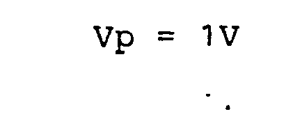
- The above values are for charging and thus the left terms of the equations (40) to (43) vary for open-circuit condition and/or discharging. As a result, in order to satisfy the equations (40) to (43) with the resistances being fixed, it is only necessary to vary the value of the shunt current i correspondingly. Namely, the value of Vp in the equation (39) is varied. The following Table 1 shows the specific values corresponding to these conditions.

- Fig. 7 shows by way of example the five-layer cell stack zinc bromide battery constructed in accordance with the above-mentioned design. The channels each has a diameter and length corresponding to the previously mentioned design resistance value. The corresponding relations between the channels and the resistances are as follows: Rc1 → 25, 33, Rc2 → 26, 34, Rc3 →27, 35, ... , Ra1 → 29, 37, Ra2 → 30, 38, Ra3 → 31, 39, ... , etc.
- The
electrodes common manifolds electrodes common manifolds electrodes auxiliary power supply 76 whose positive terminal is connected to acathode terminal 18 of the cell stack secondary battery. Theelectrodes auxiliary power supply 79 whose negative terminal is connected to ananode terminal 75 of the cell stack secondary battery. - Fig. 9 shows the measurements of the values of the shunt currents which were supplied to the respective channels when ten cycles of three patterns, i.e., charge, open-circuit and discharge were performed in the five-layer zinc bromide secondary battery. The abscissa represents the numbers of the secondary cell cathode in order of increasing voltage and the ordinate represents the corresponding measured values. In the Figures, marks of "0" indicate the measured values obtained in accordance with the invention and marks of "1" indicate those obtained without the application of the invention, that is, those obtained by replacing the channel portions of the respective cells with the conventional ones to make the cells equal in channel electric resistance (all the channel electric resistances ≒ 1500 n ). Fig. 9 shows cathode current distribution diagrams showing the values of the currents through the cathode of the respective cells whichwere obtained from the shunt current values obtained in the above-mentioned manner and which were shown in terms of the value of the current through the lowest voltage cathode as a zero point. If the time factor is involved in the current values, these diagrams show charged electricity quantity distributions in terms of mA.Hr. In Fig. 9,(a) shows the distribution for charging condition, (b) the distribution for open-circuit condition (c) the distribution for discharging condition. As will be seen from the diagrams in (a), (b) and (c) of Fig. 9, the currents through the cathode are not the same in the case without the application of the invention (marked "0") and the existence of unequality of quantity of electricity is presumed, whereas the existence of equality of quantity of electricity is seen in the case using the present invention (marked "0"). After the ten cycles of operation, the electrodeposition of zinc on the cathode was examined with the result that there was the electrodeposition of the dendritic zinc on the cathode near the channels in the case without the application of the invention and that there was no trace of such abnormal electrodeposition in the case using the invention.
- Also, the results of the calculations made from the measured shunt current values and the electrolyte electric resistance values in the manifolds and the channels showed that in the case using the invention the loss was 0.48 W showing only a slight increase over 0.14 W of the case without the application of the invention. On the other hand, in the case of the cell stack battery using the protective current according to the U.S.P. No. 4,197,169 but without the application of the invention the required protective current was about 32 mA and the calculated value of the loss due to the protective current was estimated to amount to 3.6 W. It will be seen from the foregoing that the present invention can realize a cell stack secondary battery which is small in loss, reduces the difficulties due to shunt current and is long in cycle life.
- While, in the above-described embodiment, the
electrodes electrodes catholyte channels electrodes - The present invention comprises the following solutions for providing improvements relating to the deficiencies due to shunt current, i.e., the occurrence of abnormal elec- trodeposition, unequality of quantity of charged electricity and shunt current loss.
- In other words, in the anode chambers on the high voltage side shunt currents flow out to the anolyte manifolds from the anode chambers and shunt currents are introduced from the anolyte manifolds into the anode chambers on the low voltage side. In this case, the potential of the electrodes fitted into the catholyte manifolds is adjusted by the auxiliary power supply in such a manner that in the secondary cells on the low voltage side the value of a shunt current flowing out of the catholyte chamber becomes higher than that of a shunt current flowing into the anode chamber.
- On the other hand, any unequality of quantity of charged electricity is caused by the fact that the sum total of the shunt currents flowing in and out through the channels is not zero in each of the secondary cells of the cell stack secondary battery except the highest voltage cell. Thus, in an attempt to overcome this deficiency additional channels and an additional manifold are provided to connect the anode chambers of the secondary cells to each other and an additional electrode is fitted into the additional channel or the additional manifold and connected to the positive terminal of the cell stack secondary battery through an auxiliary power supply. While a small current flows into the anode chambers from this additional electrode, as will be described later, considering the size of the channels and the manifold interconnecting the anode chambers, the internal electrolyte electric resistances of the channels and the manifold are adjusted in such a manner that a current for supplementing the small currents flowing out of the secondary cells is supplied into the anode chambers through the channels and the manifold interconnecting these chambers and thus the small currents flowing in and out are reduced to zero on the whole in each of the secondary cells of the cell stack secondary battery except the highest voltage cell, thereby overcoming the problem of unequality of quantity of charged electricity.
- Fig. 10 is a longitudinal sectional view showing a three- layer cell stack secondary battery with shunt current protective means according to another embodiment of the invention, in which
additional channels additional manifold 85 are connected to therespective anode chambers additional electrode 86 is fitted into the manifold 85 and is hermetically fixed in place. Theelectrode 86 is connected by means of a connectingmember 87 to theauxiliary power supply 79 connected to thepositive terminal 75. - Next, description will be made of the method of adjusting the internal electrolyte electric resistances of the additionally provided
manifold 85 andchannels channels - Fig. 11 illustrates a resistance equivalent circuit corresponding to the three-layer cell stack secondary battery of Fig. 10, and the symbols in the Figure denote as follows:
- Vo: secondary cell open-circuit voltage.
- Re: secondary cell internal resistance.
- R1, R2, R3 : overall equivalent resistances of the internal electrolyte electric resistances of the catholyte and anolyte outlet and inlet common manifolds and channels.
- i1, i2, i3 : values of shunt currents flowing to the above equivalent resistances, that is, in the case of Fig. 10 where the
electrodes electrodes auxiliary power supply 76 lower than the cathode terminal of the cell stack battery, i1 represents the overall value of currents through thechannels secondary cell 1, i2 the similar current value for thesecondary cell 2, and i3 the similar current value for thesecondary cell 3. These current values correspond to those obtained in the case without the provision of the manifold 85 and thechannels anode chambers - I1, I2, I3 : value of currents flowing to the
secondary cells additional manifold 85 and thechannels anode chambers - Rcl,Rc2,Rc3: internal electrolyte electric resistance values of the additionally provided
channels - Rm , Rm2 : manifold internal electrolyte electric resistances between the additionally provided
channels - Rp : internal electrolyte electric resistance of the manifold 85 between the additionally provided electrode and the junction of the manifold 85 and the
channel 84 of the additionally providedchannels - Vpa : voltage of the auxiliary power supply (79 in Fig. 10).
- Vpc : voltage of the auxiliary power supply (76 in Fig. 10)
- J : sum of currents flowing into the secondary cells via the additionally provided
manifold 85 andchannels - I + J: input/output current of the cell stack secondary battery.
- With this circuit, it is the purpose of the invention to set the values of Rc1 to Rc3, Rm1, Rm2 and Rp such that the current through the cathode of each cell or the charged electricity of each cathode is uniform.
- In the equivalent circuit of Fig. 11, the essential requirement is to arrange such that the current through Vo and Re have a fixed value. If this fixed value is represent by a , then the following equations are obtained
-



- In other words, the following conditions are essential to ensure the equality of quantity of charged electricity


- Also, the following circuit equations relating to Rc1, Rc2, Rc3, Rm1, Rm2 and Rp are obtained


- As a result, it is only necessary that the values of i1, i2 and i3 are determined first and then the values of Rc1 to Rc3, Rm1, Rm2 and Rp are set by using the equations (47) to (51).
- In applying the present invention to the three-layer cell stack secondary battery, the following conditions are added.


- Now, the method of determining the values of Rc1, Rc2 and Rc3 from the
equations 54, 55 and 56 will be described with reference to a case where the present invention is applied to a three-layer ZnBr2 cell stack secondary battery. - To obtain the values of i1, i2 and i3, the
electrodes channels electrodes auxiliary power supply 76 lower than the cathode terminal of the cell stack secondary battery. Then the battery is operated with the following charging conditions. each secondary cell charging voltage Vo + IRe ≒ 2.0 V charging current I = 25 A auxiliary supply voltage Vpc = 1.0 V - The values of the shunt currents flowing through the electrolyte circulation channels (25, 29, 26, 30, 27, 31 and 33, 34, 35, 36, 37, 38 shown in Fig. 10) are measured with a clip-on ammeter and then the sum totals of the shunt currents flowing out of the respective secondary cells are obtained as follows:





- Fig. 12 shows the test results of the present embodiment. The values of currents through the cathode of the three-layer battery were measured by converting the currents through the respective channels and the current through the cathode (11 in Fig. 10) of the secondary cell having the lowest voltage among the cells of the three- layers of the secondary battery is selected as a zero point, thereby comparing the currents through the respective cathode and showing the resulting distribution of the quantities of charged electricity in the respective secondary cells. In the Figure, the ordinate represents the cathode current and the abscissa represents the secondary cell cathode.
- Marked "e" is the case where the
electrodes channels - Marked "△" is the case where the
electrodes auxiliary power supply 76 was lower by 2 V than the cathode terminal of the cell stack secondary battery. - Marked "O" is the case where the manifold 85 and the
channels electrodes electrode 86 was higher by 2 V than the anode terminal of the cell stack secondary battery. - As shown in Fig. 12, it will be seen that in accordance with the present invention the currents flowing through the cathode of the respective cells are substantially the same with the resulting decrease in the unequality of quantity of charged electricity.
- When the test was continued for ten hours in each of the cases and the electrodeposition of zinc on the surface of the cathode was examined for comparison purposes, there was the electrodeposition of the dendritic zinc on the cathode ends near the channels in the case corresponding to the cell stack secondary battery without the application of the invention (Marked "•" in Fig. 12), and there was no trace of such abnormal electrodeposition in the cases of this embodiment incorporating the invention (marked "A" and "O" in Fig. 12).
- Then, the loss due to the protective current was estimated on the basis of the currents through the channels and the manifolds and the internal electrolyte electric resistances of the manifolds .and the channels and the results showed that in the case using the invention (marked "O" in Fig. 12) the loss was 208 mW and this was greater than 56 mW obtained in the case without the application of the invention (marked "0" in Fig. 12). However, where the protective current according to U.S.P. No. 4,197,169 was applied to. the known type of battery without using the invention, the required protective current was 364 mA and the calculated value of the lose due the protective current was estimated to amount to 2,200 m.W.
- From the foregoing it will be seen that in accordance with this embodiment a cell stack secondary battery is provided which reduces the loss due to the protective current, reduces the deficiencies due to the flow of shunt current and increases the cycle life. Note that in some cases the
cathode - Fig. 13 is a longitudinal sectional view showing a cell stack secondary battery with shunt current protective means according to still another embodiment of the invention. In this embodiment, the catholyte manifolds 21 and 22 are respectively connected to the anolyte manifolds 23 and 24 by
pipes separators pipes electrodes present embodiment electrodes pipes separators electrodes connector 55 and are held at the same potential as the cathode 11 of thesecondary cell 1. Theelectrodes secondary cell 1 form a cell since theelectrodes separators auxiliary power supply 76, in the present embodiment theelectrodes auxiliary power supply 76. - Thus, the cell stack secondary battery of this embodiment functions practically in the same manner as the embodiment of Fig. 10. Of course, the present embodiment may include the
auxiliary power supply 76 so as to adjust the potential of theelectrodes - Fig. 14 is a longitudinal sectional view showing a cell stack secondary battery with shunt current protective means according to still another embodiment of the invention. This embodiment differs from the embodiment of Fig. 13 in that the
electrode 86 fitted into the manifold 85 is eliminated and its function is served by theanode 12 of thesecondary cell 3. - In applying this invention to this three-layer cell stack secondary battery, the current (i1 + i2 + i3) is supplied from the
electrode 86 on the basis of the following assumption.
electrode 86 and theauxiliary power supply 79 in the embodiment of Fig. 10 or 13 may be eliminated. - Thus, it is only necessary to determine the values of Rc1, Rc2 and RC3 by using the following two equations in place of the equations (54), (55) and (56)


- In this case, it is possible to fit the
electrode 86 into the manifold 85 and connect it to theanode 12 as shown by the phantom line in Fig. 14 so as to apply a potential thereto. By using the auxiliary power supplies, it is possible to set the anode and cathode terminal side manifold potentials to any desired low or high values and thus it is possible to reduce the channel and manifold electric resistance losses required for attaining the condition for realizing the invention, that is, the condition that the current flowing out of the cathode chamber is equal to the current flowing out of the anode chamber. - From the foregoing description it will be seen that the cell stack secondary battery with shunt current protective means according to the invention has the effect of making the current flowing out of the cathode chamber equal to the current flowing out of the anode chamber and thereby eliminating the occurrence of abnormal electrodeposition and the unequality of quantity of charged electricity and reducing the shunt current loss. Thus, the invention can be said to be very useful in practical applications.
Claims (10)
Priority Applications (2)
| Application Number | Priority Date | Filing Date | Title |
|---|---|---|---|
| EP82302273A EP0093213B1 (en) | 1982-05-04 | 1982-05-04 | Electrolytes circulation type cell stack secondary battery |
| DE8282302273T DE3277276D1 (en) | 1982-05-04 | 1982-05-04 | Electrolytes circulation type cell stack secondary battery |
Applications Claiming Priority (1)
| Application Number | Priority Date | Filing Date | Title |
|---|---|---|---|
| EP82302273A EP0093213B1 (en) | 1982-05-04 | 1982-05-04 | Electrolytes circulation type cell stack secondary battery |
Related Child Applications (1)
| Application Number | Title | Priority Date | Filing Date |
|---|---|---|---|
| EP86201025.3 Division-Into | 1982-05-04 |
Publications (2)
| Publication Number | Publication Date |
|---|---|
| EP0093213A1 true EP0093213A1 (en) | 1983-11-09 |
| EP0093213B1 EP0093213B1 (en) | 1987-09-09 |
Family
ID=8189658
Family Applications (1)
| Application Number | Title | Priority Date | Filing Date |
|---|---|---|---|
| EP82302273A Expired EP0093213B1 (en) | 1982-05-04 | 1982-05-04 | Electrolytes circulation type cell stack secondary battery |
Country Status (2)
| Country | Link |
|---|---|
| EP (1) | EP0093213B1 (en) |
| DE (1) | DE3277276D1 (en) |
Cited By (4)
| Publication number | Priority date | Publication date | Assignee | Title |
|---|---|---|---|---|
| EP0109727A3 (en) * | 1982-11-22 | 1985-01-09 | Exxon Research And Engineering Company | Electrochemical device |
| WO1987007768A1 (en) * | 1986-06-16 | 1987-12-17 | Seregie | Reversible electric battery with circulating electrolyte |
| US8293390B2 (en) | 2007-03-28 | 2012-10-23 | Redflow Pty Ltd | Cell stack for a flowing electrolyte battery |
| EP3522280A4 (en) * | 2016-09-30 | 2020-07-01 | Lotte Chemical Corporation | REDOX FLOW CELL |
Families Citing this family (1)
| Publication number | Priority date | Publication date | Assignee | Title |
|---|---|---|---|---|
| EP2311119B1 (en) * | 2008-08-22 | 2018-02-21 | RedFlow R&D Pty Ltd | Integral manifold |
Citations (3)
| Publication number | Priority date | Publication date | Assignee | Title |
|---|---|---|---|---|
| US4197169A (en) * | 1978-09-05 | 1980-04-08 | Exxon Research & Engineering Co. | Shunt current elimination and device |
| EP0034492A2 (en) * | 1980-02-19 | 1981-08-26 | Exxon Research And Engineering Company | Electrochemical device having means for reducing shunt current |
| EP0039571A1 (en) * | 1980-04-28 | 1981-11-11 | Exxon Research And Engineering Company | Shunt current protection for circulating electrolyte in monopolar battery systems |
Family Cites Families (1)
| Publication number | Priority date | Publication date | Assignee | Title |
|---|---|---|---|---|
| EP0089433B1 (en) * | 1982-03-24 | 1986-09-17 | Kabushiki Kaisha Meidensha | Secondary battery |
-
1982
- 1982-05-04 EP EP82302273A patent/EP0093213B1/en not_active Expired
- 1982-05-04 DE DE8282302273T patent/DE3277276D1/en not_active Expired
Patent Citations (3)
| Publication number | Priority date | Publication date | Assignee | Title |
|---|---|---|---|---|
| US4197169A (en) * | 1978-09-05 | 1980-04-08 | Exxon Research & Engineering Co. | Shunt current elimination and device |
| EP0034492A2 (en) * | 1980-02-19 | 1981-08-26 | Exxon Research And Engineering Company | Electrochemical device having means for reducing shunt current |
| EP0039571A1 (en) * | 1980-04-28 | 1981-11-11 | Exxon Research And Engineering Company | Shunt current protection for circulating electrolyte in monopolar battery systems |
Cited By (6)
| Publication number | Priority date | Publication date | Assignee | Title |
|---|---|---|---|---|
| EP0109727A3 (en) * | 1982-11-22 | 1985-01-09 | Exxon Research And Engineering Company | Electrochemical device |
| WO1987007768A1 (en) * | 1986-06-16 | 1987-12-17 | Seregie | Reversible electric battery with circulating electrolyte |
| FR2600214A1 (en) * | 1986-06-16 | 1987-12-18 | Serggie | REVERSIBLE ELECTRIC BATTERY WITH CIRCULATED ELECTROLYTE |
| US8293390B2 (en) | 2007-03-28 | 2012-10-23 | Redflow Pty Ltd | Cell stack for a flowing electrolyte battery |
| CN101647138B (en) * | 2007-03-28 | 2012-11-14 | 红流私人有限公司 | Cell stack for a flowing electrolyte battery |
| EP3522280A4 (en) * | 2016-09-30 | 2020-07-01 | Lotte Chemical Corporation | REDOX FLOW CELL |
Also Published As
| Publication number | Publication date |
|---|---|
| EP0093213B1 (en) | 1987-09-09 |
| DE3277276D1 (en) | 1987-10-15 |
Similar Documents
| Publication | Publication Date | Title |
|---|---|---|
| CA1130854A (en) | Shunt current elimination in electrochemical devices | |
| US7811701B2 (en) | Battery assembly | |
| EP1551074B1 (en) | Method for operating redox flow battery and redox flow battery cell stack | |
| US4100332A (en) | Comb type bipolar electrode elements and battery stacks thereof | |
| GB2070321A (en) | Shunt current elimination | |
| JPH0584132B2 (en) | ||
| EP0165000A2 (en) | Metal-halogen secondary battery | |
| US11211650B2 (en) | Battery with temperature control device and method for regulating the temperature of a battery | |
| GB2569140A (en) | Battery management | |
| JPH02216772A (en) | Zinc-bromine battery | |
| KR20180023750A (en) | Flow frame for redox flow battery | |
| AU2017290026A1 (en) | Redox flow battery, electrical quantity measurement system, and electrical quantity measurement method | |
| EP0093213A1 (en) | Electrolytes circulation type cell stack secondary battery | |
| US4520080A (en) | Electrolytes circulation type cell stack secondary battery | |
| US5391973A (en) | Method of charging a multiplicity of batteries | |
| US4718997A (en) | Electrochemical device | |
| EP0208358B1 (en) | Battery stack of secondary cells | |
| Hagedorn et al. | NASA-Redox cell-stack shunt current, pumping power, and cell-performance tradeoffs | |
| US4416953A (en) | Secondary battery | |
| EP0089433B1 (en) | Secondary battery | |
| CA1173897A (en) | Electrolytes circulation type cell stack secondary battery | |
| US12609339B2 (en) | High voltage-type redox flow battery comprising SOC balancing device | |
| JP3574514B2 (en) | Redox flow type secondary battery system | |
| JP2931650B2 (en) | Electrolyte circulation type secondary battery | |
| CA1190594A (en) | Electrochemical device |
Legal Events
| Date | Code | Title | Description |
|---|---|---|---|
| PUAI | Public reference made under article 153(3) epc to a published international application that has entered the european phase |
Free format text: ORIGINAL CODE: 0009012 |
|
| AK | Designated contracting states |
Designated state(s): DE FR GB IT |
|
| 17P | Request for examination filed |
Effective date: 19840425 |
|
| GRAA | (expected) grant |
Free format text: ORIGINAL CODE: 0009210 |
|
| ITF | It: translation for a ep patent filed | ||
| AK | Designated contracting states |
Kind code of ref document: B1 Designated state(s): DE FR GB IT |
|
| REF | Corresponds to: |
Ref document number: 3277276 Country of ref document: DE Date of ref document: 19871015 |
|
| ET | Fr: translation filed | ||
| PLBE | No opposition filed within time limit |
Free format text: ORIGINAL CODE: 0009261 |
|
| STAA | Information on the status of an ep patent application or granted ep patent |
Free format text: STATUS: NO OPPOSITION FILED WITHIN TIME LIMIT |
|
| 26N | No opposition filed | ||
| ITTA | It: last paid annual fee | ||
| PGFP | Annual fee paid to national office [announced via postgrant information from national office to epo] |
Ref country code: GB Payment date: 19960419 Year of fee payment: 15 |
|
| PGFP | Annual fee paid to national office [announced via postgrant information from national office to epo] |
Ref country code: FR Payment date: 19960426 Year of fee payment: 15 |
|
| PGFP | Annual fee paid to national office [announced via postgrant information from national office to epo] |
Ref country code: DE Payment date: 19960625 Year of fee payment: 15 |
|
| PG25 | Lapsed in a contracting state [announced via postgrant information from national office to epo] |
Ref country code: GB Effective date: 19970504 |
|
| GBPC | Gb: european patent ceased through non-payment of renewal fee |
Effective date: 19970504 |
|
| PG25 | Lapsed in a contracting state [announced via postgrant information from national office to epo] |
Ref country code: FR Free format text: LAPSE BECAUSE OF NON-PAYMENT OF DUE FEES Effective date: 19980130 |
|
| PG25 | Lapsed in a contracting state [announced via postgrant information from national office to epo] |
Ref country code: DE Free format text: LAPSE BECAUSE OF NON-PAYMENT OF DUE FEES Effective date: 19980203 |
|
| REG | Reference to a national code |
Ref country code: FR Ref legal event code: ST |