EP0092340B1 - Method of clay stabilisation in enhanced oil recovery - Google Patents
Method of clay stabilisation in enhanced oil recovery Download PDFInfo
- Publication number
- EP0092340B1 EP0092340B1 EP83301927A EP83301927A EP0092340B1 EP 0092340 B1 EP0092340 B1 EP 0092340B1 EP 83301927 A EP83301927 A EP 83301927A EP 83301927 A EP83301927 A EP 83301927A EP 0092340 B1 EP0092340 B1 EP 0092340B1
- Authority
- EP
- European Patent Office
- Prior art keywords
- polymer
- clay
- flow rate
- cationic
- anionic
- Prior art date
- Legal status (The legal status is an assumption and is not a legal conclusion. Google has not performed a legal analysis and makes no representation as to the accuracy of the status listed.)
- Expired
Links
- 239000004927 clay Substances 0.000 title claims description 85
- 238000000034 method Methods 0.000 title claims description 29
- 238000011084 recovery Methods 0.000 title claims description 16
- 230000006641 stabilisation Effects 0.000 title description 22
- 229920000642 polymer Polymers 0.000 claims description 137
- WCUXLLCKKVVCTQ-UHFFFAOYSA-M Potassium chloride Chemical compound [Cl-].[K+] WCUXLLCKKVVCTQ-UHFFFAOYSA-M 0.000 claims description 62
- 239000012530 fluid Substances 0.000 claims description 62
- 125000002091 cationic group Chemical group 0.000 claims description 46
- 238000011282 treatment Methods 0.000 claims description 45
- 229920000620 organic polymer Polymers 0.000 claims description 42
- 239000000126 substance Substances 0.000 claims description 37
- 239000001103 potassium chloride Substances 0.000 claims description 31
- 235000011164 potassium chloride Nutrition 0.000 claims description 31
- 125000000129 anionic group Chemical group 0.000 claims description 29
- 239000003518 caustics Substances 0.000 claims description 24
- XLYOFNOQVPJJNP-UHFFFAOYSA-N water Substances O XLYOFNOQVPJJNP-UHFFFAOYSA-N 0.000 claims description 20
- 235000002639 sodium chloride Nutrition 0.000 claims description 16
- FAPWRFPIFSIZLT-UHFFFAOYSA-M Sodium chloride Chemical compound [Na+].[Cl-] FAPWRFPIFSIZLT-UHFFFAOYSA-M 0.000 claims description 11
- NLXLAEXVIDQMFP-UHFFFAOYSA-N Ammonia chloride Chemical compound [NH4+].[Cl-] NLXLAEXVIDQMFP-UHFFFAOYSA-N 0.000 claims description 10
- 150000003839 salts Chemical class 0.000 claims description 9
- 239000011780 sodium chloride Substances 0.000 claims description 7
- 230000000694 effects Effects 0.000 claims description 6
- 230000003019 stabilising effect Effects 0.000 claims description 6
- 235000019270 ammonium chloride Nutrition 0.000 claims description 5
- 239000000203 mixture Substances 0.000 claims description 4
- VEXZGXHMUGYJMC-UHFFFAOYSA-M Chloride anion Chemical compound [Cl-] VEXZGXHMUGYJMC-UHFFFAOYSA-M 0.000 claims description 2
- QVGXLLKOCUKJST-UHFFFAOYSA-N atomic oxygen Chemical group [O] QVGXLLKOCUKJST-UHFFFAOYSA-N 0.000 claims description 2
- 125000005842 heteroatom Chemical group 0.000 claims description 2
- 239000001301 oxygen Substances 0.000 claims description 2
- 229910052760 oxygen Inorganic materials 0.000 claims description 2
- 239000000243 solution Substances 0.000 description 65
- 239000012267 brine Substances 0.000 description 55
- HPALAKNZSZLMCH-UHFFFAOYSA-M sodium;chloride;hydrate Chemical compound O.[Na+].[Cl-] HPALAKNZSZLMCH-UHFFFAOYSA-M 0.000 description 54
- 125000006850 spacer group Chemical group 0.000 description 51
- 239000013505 freshwater Substances 0.000 description 47
- 238000002347 injection Methods 0.000 description 46
- 239000007924 injection Substances 0.000 description 46
- 239000003921 oil Substances 0.000 description 40
- 239000011148 porous material Substances 0.000 description 40
- 230000015572 biosynthetic process Effects 0.000 description 35
- 238000005755 formation reaction Methods 0.000 description 35
- HEMHJVSKTPXQMS-UHFFFAOYSA-M Sodium hydroxide Chemical compound [OH-].[Na+] HEMHJVSKTPXQMS-UHFFFAOYSA-M 0.000 description 30
- 239000003381 stabilizer Substances 0.000 description 26
- 230000035699 permeability Effects 0.000 description 21
- 238000012360 testing method Methods 0.000 description 20
- 238000002474 experimental method Methods 0.000 description 19
- 238000011105 stabilization Methods 0.000 description 18
- 229920002401 polyacrylamide Polymers 0.000 description 14
- 230000003993 interaction Effects 0.000 description 13
- 239000004094 surface-active agent Substances 0.000 description 13
- 239000003208 petroleum Substances 0.000 description 12
- GQOKIYDTHHZSCJ-UHFFFAOYSA-M dimethyl-bis(prop-2-enyl)azanium;chloride Chemical compound [Cl-].C=CC[N+](C)(C)CC=C GQOKIYDTHHZSCJ-UHFFFAOYSA-M 0.000 description 11
- 239000002244 precipitate Substances 0.000 description 11
- BDHFUVZGWQCTTF-UHFFFAOYSA-M sulfonate Chemical compound [O-]S(=O)=O BDHFUVZGWQCTTF-UHFFFAOYSA-M 0.000 description 10
- 239000010779 crude oil Substances 0.000 description 9
- 238000004519 manufacturing process Methods 0.000 description 9
- 239000004115 Sodium Silicate Substances 0.000 description 8
- COCAUCFPFHUGAA-MGNBDDOMSA-N n-[3-[(1s,7s)-5-amino-4-thia-6-azabicyclo[5.1.0]oct-5-en-7-yl]-4-fluorophenyl]-5-chloropyridine-2-carboxamide Chemical compound C=1C=C(F)C([C@@]23N=C(SCC[C@@H]2C3)N)=CC=1NC(=O)C1=CC=C(Cl)C=N1 COCAUCFPFHUGAA-MGNBDDOMSA-N 0.000 description 8
- 230000009467 reduction Effects 0.000 description 8
- NTHWMYGWWRZVTN-UHFFFAOYSA-N sodium silicate Chemical compound [Na+].[Na+].[O-][Si]([O-])=O NTHWMYGWWRZVTN-UHFFFAOYSA-N 0.000 description 8
- 229910052911 sodium silicate Inorganic materials 0.000 description 8
- 238000006243 chemical reaction Methods 0.000 description 7
- 238000010828 elution Methods 0.000 description 7
- 239000003350 kerosene Substances 0.000 description 7
- 239000011435 rock Substances 0.000 description 7
- JEIPFZHSYJVQDO-UHFFFAOYSA-N iron(III) oxide Inorganic materials O=[Fe]O[Fe]=O JEIPFZHSYJVQDO-UHFFFAOYSA-N 0.000 description 6
- 239000002245 particle Substances 0.000 description 6
- 239000004576 sand Substances 0.000 description 6
- 239000008367 deionised water Substances 0.000 description 5
- 229910021641 deionized water Inorganic materials 0.000 description 5
- 239000000839 emulsion Substances 0.000 description 5
- NLYAJNPCOHFWQQ-UHFFFAOYSA-N kaolin Chemical compound O.O.O=[Al]O[Si](=O)O[Si](=O)O[Al]=O NLYAJNPCOHFWQQ-UHFFFAOYSA-N 0.000 description 5
- 229910052622 kaolinite Inorganic materials 0.000 description 5
- 229910021647 smectite Inorganic materials 0.000 description 5
- 239000003945 anionic surfactant Substances 0.000 description 4
- 239000007788 liquid Substances 0.000 description 4
- CDBYLPFSWZWCQE-UHFFFAOYSA-L sodium carbonate Substances [Na+].[Na+].[O-]C([O-])=O CDBYLPFSWZWCQE-UHFFFAOYSA-L 0.000 description 4
- KWYUFKZDYYNOTN-UHFFFAOYSA-M Potassium hydroxide Chemical compound [OH-].[K+] KWYUFKZDYYNOTN-UHFFFAOYSA-M 0.000 description 3
- 239000010419 fine particle Substances 0.000 description 3
- 239000007789 gas Substances 0.000 description 3
- 239000002904 solvent Substances 0.000 description 3
- 238000001179 sorption measurement Methods 0.000 description 3
- 150000003871 sulfonates Chemical class 0.000 description 3
- 230000008961 swelling Effects 0.000 description 3
- OYPRJOBELJOOCE-UHFFFAOYSA-N Calcium Chemical compound [Ca] OYPRJOBELJOOCE-UHFFFAOYSA-N 0.000 description 2
- VTYYLEPIZMXCLO-UHFFFAOYSA-L Calcium carbonate Chemical compound [Ca+2].[O-]C([O-])=O VTYYLEPIZMXCLO-UHFFFAOYSA-L 0.000 description 2
- 239000004215 Carbon black (E152) Substances 0.000 description 2
- 238000006424 Flood reaction Methods 0.000 description 2
- 229920006318 anionic polymer Polymers 0.000 description 2
- 239000011575 calcium Substances 0.000 description 2
- 229910052791 calcium Inorganic materials 0.000 description 2
- 230000007423 decrease Effects 0.000 description 2
- 230000001066 destructive effect Effects 0.000 description 2
- 238000003379 elimination reaction Methods 0.000 description 2
- 238000004945 emulsification Methods 0.000 description 2
- 239000008398 formation water Substances 0.000 description 2
- 150000004676 glycans Chemical class 0.000 description 2
- 229930195733 hydrocarbon Natural products 0.000 description 2
- 150000002430 hydrocarbons Chemical class 0.000 description 2
- 159000000003 magnesium salts Chemical class 0.000 description 2
- 230000000813 microbial effect Effects 0.000 description 2
- 230000005012 migration Effects 0.000 description 2
- 238000013508 migration Methods 0.000 description 2
- 150000007524 organic acids Chemical class 0.000 description 2
- 235000005985 organic acids Nutrition 0.000 description 2
- 230000000149 penetrating effect Effects 0.000 description 2
- 238000004391 petroleum recovery Methods 0.000 description 2
- 229920001282 polysaccharide Polymers 0.000 description 2
- 239000005017 polysaccharide Substances 0.000 description 2
- BWHMMNNQKKPAPP-UHFFFAOYSA-L potassium carbonate Substances [K+].[K+].[O-]C([O-])=O BWHMMNNQKKPAPP-UHFFFAOYSA-L 0.000 description 2
- 230000008569 process Effects 0.000 description 2
- 229910000029 sodium carbonate Inorganic materials 0.000 description 2
- POWFTOSLLWLEBN-UHFFFAOYSA-N tetrasodium;silicate Chemical compound [Na+].[Na+].[Na+].[Na+].[O-][Si]([O-])([O-])[O-] POWFTOSLLWLEBN-UHFFFAOYSA-N 0.000 description 2
- 238000012935 Averaging Methods 0.000 description 1
- 0 CCC(C)(*)N(C)C Chemical compound CCC(C)(*)N(C)C 0.000 description 1
- CDXIIEOYOOWWLT-UHFFFAOYSA-N CCC(C)(CC)N(C)C Chemical compound CCC(C)(CC)N(C)C CDXIIEOYOOWWLT-UHFFFAOYSA-N 0.000 description 1
- CHCGSQVHHOXUPD-UHFFFAOYSA-N CCC[N](C)(C)CCCC(C)C(C)CC Chemical compound CCC[N](C)(C)CCCC(C)C(C)CC CHCGSQVHHOXUPD-UHFFFAOYSA-N 0.000 description 1
- 241000237858 Gastropoda Species 0.000 description 1
- CTQNGGLPUBDAKN-UHFFFAOYSA-N O-Xylene Chemical compound CC1=CC=CC=C1C CTQNGGLPUBDAKN-UHFFFAOYSA-N 0.000 description 1
- ZLMJMSJWJFRBEC-UHFFFAOYSA-N Potassium Chemical compound [K] ZLMJMSJWJFRBEC-UHFFFAOYSA-N 0.000 description 1
- 239000004111 Potassium silicate Substances 0.000 description 1
- 229920006362 Teflon® Polymers 0.000 description 1
- 230000002411 adverse Effects 0.000 description 1
- 150000001412 amines Chemical class 0.000 description 1
- 239000007864 aqueous solution Substances 0.000 description 1
- 229910000019 calcium carbonate Inorganic materials 0.000 description 1
- AXCZMVOFGPJBDE-UHFFFAOYSA-L calcium dihydroxide Chemical compound [OH-].[OH-].[Ca+2] AXCZMVOFGPJBDE-UHFFFAOYSA-L 0.000 description 1
- 239000000920 calcium hydroxide Substances 0.000 description 1
- 229910001861 calcium hydroxide Inorganic materials 0.000 description 1
- 238000004140 cleaning Methods 0.000 description 1
- 238000000354 decomposition reaction Methods 0.000 description 1
- 230000003247 decreasing effect Effects 0.000 description 1
- 230000001419 dependent effect Effects 0.000 description 1
- 230000008021 deposition Effects 0.000 description 1
- 238000010790 dilution Methods 0.000 description 1
- 239000012895 dilution Substances 0.000 description 1
- 238000006073 displacement reaction Methods 0.000 description 1
- 230000008030 elimination Effects 0.000 description 1
- 229920006158 high molecular weight polymer Polymers 0.000 description 1
- XLYOFNOQVPJJNP-UHFFFAOYSA-M hydroxide Chemical compound [OH-] XLYOFNOQVPJJNP-UHFFFAOYSA-M 0.000 description 1
- 238000011065 in-situ storage Methods 0.000 description 1
- 238000011221 initial treatment Methods 0.000 description 1
- 150000002500 ions Chemical class 0.000 description 1
- 238000009533 lab test Methods 0.000 description 1
- 230000014759 maintenance of location Effects 0.000 description 1
- 229910021645 metal ion Inorganic materials 0.000 description 1
- 238000012986 modification Methods 0.000 description 1
- 230000004048 modification Effects 0.000 description 1
- 230000007935 neutral effect Effects 0.000 description 1
- 239000002736 nonionic surfactant Substances 0.000 description 1
- 230000010399 physical interaction Effects 0.000 description 1
- -1 poly(diallyldimethylammonium chloride) Polymers 0.000 description 1
- 229920000371 poly(diallyldimethylammonium chloride) polymer Polymers 0.000 description 1
- 239000011591 potassium Substances 0.000 description 1
- 229910052700 potassium Inorganic materials 0.000 description 1
- 229910000027 potassium carbonate Inorganic materials 0.000 description 1
- NNHHDJVEYQHLHG-UHFFFAOYSA-N potassium silicate Chemical compound [K+].[K+].[O-][Si]([O-])=O NNHHDJVEYQHLHG-UHFFFAOYSA-N 0.000 description 1
- 229910052913 potassium silicate Inorganic materials 0.000 description 1
- 235000019353 potassium silicate Nutrition 0.000 description 1
- 150000003242 quaternary ammonium salts Chemical class 0.000 description 1
- 239000012266 salt solution Substances 0.000 description 1
- GCLGEJMYGQKIIW-UHFFFAOYSA-H sodium hexametaphosphate Chemical compound [Na]OP1(=O)OP(=O)(O[Na])OP(=O)(O[Na])OP(=O)(O[Na])OP(=O)(O[Na])OP(=O)(O[Na])O1 GCLGEJMYGQKIIW-UHFFFAOYSA-H 0.000 description 1
- 239000007787 solid Substances 0.000 description 1
- 230000000087 stabilizing effect Effects 0.000 description 1
- 238000010998 test method Methods 0.000 description 1
- 229920001285 xanthan gum Polymers 0.000 description 1
- 239000000230 xanthan gum Substances 0.000 description 1
- 229940082509 xanthan gum Drugs 0.000 description 1
- 235000010493 xanthan gum Nutrition 0.000 description 1
- 239000008096 xylene Substances 0.000 description 1
Classifications
-
- C—CHEMISTRY; METALLURGY
- C09—DYES; PAINTS; POLISHES; NATURAL RESINS; ADHESIVES; COMPOSITIONS NOT OTHERWISE PROVIDED FOR; APPLICATIONS OF MATERIALS NOT OTHERWISE PROVIDED FOR
- C09K—MATERIALS FOR MISCELLANEOUS APPLICATIONS, NOT PROVIDED FOR ELSEWHERE
- C09K8/00—Compositions for drilling of boreholes or wells; Compositions for treating boreholes or wells, e.g. for completion or for remedial operations
- C09K8/58—Compositions for enhanced recovery methods for obtaining hydrocarbons, i.e. for improving the mobility of the oil, e.g. displacing fluids
- C09K8/588—Compositions for enhanced recovery methods for obtaining hydrocarbons, i.e. for improving the mobility of the oil, e.g. displacing fluids characterised by the use of specific polymers
-
- C—CHEMISTRY; METALLURGY
- C09—DYES; PAINTS; POLISHES; NATURAL RESINS; ADHESIVES; COMPOSITIONS NOT OTHERWISE PROVIDED FOR; APPLICATIONS OF MATERIALS NOT OTHERWISE PROVIDED FOR
- C09K—MATERIALS FOR MISCELLANEOUS APPLICATIONS, NOT PROVIDED FOR ELSEWHERE
- C09K8/00—Compositions for drilling of boreholes or wells; Compositions for treating boreholes or wells, e.g. for completion or for remedial operations
- C09K8/60—Compositions for stimulating production by acting on the underground formation
- C09K8/607—Compositions for stimulating production by acting on the underground formation specially adapted for clay formations
- C09K8/608—Polymer compositions
-
- Y—GENERAL TAGGING OF NEW TECHNOLOGICAL DEVELOPMENTS; GENERAL TAGGING OF CROSS-SECTIONAL TECHNOLOGIES SPANNING OVER SEVERAL SECTIONS OF THE IPC; TECHNICAL SUBJECTS COVERED BY FORMER USPC CROSS-REFERENCE ART COLLECTIONS [XRACs] AND DIGESTS
- Y10—TECHNICAL SUBJECTS COVERED BY FORMER USPC
- Y10S—TECHNICAL SUBJECTS COVERED BY FORMER USPC CROSS-REFERENCE ART COLLECTIONS [XRACs] AND DIGESTS
- Y10S507/00—Earth boring, well treating, and oil field chemistry
- Y10S507/935—Enhanced oil recovery
- Y10S507/936—Flooding the formation
Definitions
- the present invention relates to a method of clay stabilisation in oil reservoirs that are subject to anionic or caustic chemical flooding via enhanced oil recovery techniques.
- the energy required to force oil into producing wells is supplied by the natural pressure drive existing in the formation or by mechanically lifting oil from the formation through the well bores of producing wells to the surface.
- the energy required to force oil into producing wells is supplied by the natural pressure drive existing in the formation or by mechanically lifting oil from the formation through the well bores of producing wells to the surface.
- a substantial quantity of oil remains in the formation.
- energy for producing oil remaining in the subterranean oil-containing formation is supplied by injecting liquids or gases into the formation under pressure through one or more injection wells penetrating the formation. The liquids or gases drive the oil to producing wells penetrating the formation.
- U.S. specification no. 3797574 describes the use of water as a drive liquid.
- the water contains a surfactant to reduce interfacial tension between the water and the oil.
- a preflush slug of water containing a quaternary ammonium salt is used.
- U.S. specification no. 2800962 also describes the use of water containing a surfactant as a drive liquid, at least two batches of such water being used each batch containing different type of surfactant from that used in the preceding batch.
- caustic flooding Three further common methods of artifically maintaining formation presure and increasing oil recovery are caustic flooding, polymer flooding and micellar polymer flooding.
- Caustic flooding is an enhanced oil recovery process often effectively used in formations containing crude oil having significant concentrations of organic acids.
- a high pH injected solution reacts with the organic acids in the crude oil to produce an emulsion which is considered to entrain or entrap the oil for movement as sell as reduce the interfacial tension between the injected high pH solution and the crude oil.
- Chemicals used to produce the high pH in the injection fluid include sodium hydroxide, sodium carbonate, and sodium silicate, including especially sodium ortho-silicate.
- Other bases such as potassium hydroxide, potassium carbonate, and potassium silicate could also be used.
- Another type of enhanced oil recovery technique is polymer flooding.
- a high molecular weight polymer is used to thicken the injection water.
- the thickened water more effectively pushes the crude oil to a producing well and also aids in increasing the volume of the reservoir contacted by the injected fluid. This results in greater oil production.
- the most commonly used enhanced oil recovery polymers are anionic chemicals such as partially hydrolised polyacrylamides and certain microbial polysaccharides, especially xanthan gum.
- U.K. specification 2091320 describes one special example of polymer flooding.
- the formation is treated with a fluid comprising two polymers, the first being a viscosifier and the second being polycationic and functioning to reduce the viscosity of the fluid. In use, the fluid has a low viscosity as it is pumped into the formation but, once in place, the second polymer is absorbed resulting in an increase in the solution viscosity.
- micellar polymer flooding introduces a surfactant to reduce the interfacial tension between the oil prior to injecting flood water. Such reduction of the interfacial tension will cause the oil to be more readily displaced thereby increasing production.
- the most commonly used surfactants are anionic chemicals such as petroleum sulfonates or sulfonates of various hydrocarbon refinery streams.
- anionic polymers such as partially hydrolyzed polyacrylamides and certain microbial polysaccharides can also be used to thicken the water injected after the surfactant solution. This prevents the injection water from fingering through the surfactant solution, contacting the crude oil, and increasing the interfacial tension thereby reducing oil recovery.
- caustic flood techniques and polymer or micellar polymer flood techniques is effected in a lower salinity environment that adversely affects reservoir conditions by more readily causing clay swelling and migration of fine particles leading to reduced formation permeability.
- cationic organic polymers have been successfully used for preventing permeability damage due to clay swelling and disintegration in subterranean formations during oil and gas production, such polymers have been ineffective when used in conjuction with these enhanced oil recovery processes.
- the cationic organic polymers form precipitates when they contact anionic chemicals.
- the high pH solution thereof causes the cationic organic polymers to undergo a bimolecular elimination reaction which converts cationic nitrogen atoms to amines exemplified as follows:
- the molecular weight of the clay stabilizer can also be substantially reduced when the cationic atom is part of the polymer backbone, as exemplified in the following equation: It should be noted in Equations 1 and 2 that such reactions also consume the caustic chemical injected into the formation.
- a method of enhanced oil recovery treatment of a subterranean oil reservoir with anionic or caustic flood chemicals comprises introducing into the reservoir treatment area a cationic substance, and then introducing anionic or caustic flood chemicals to effect said treatment; characterised in that: the cationic substance is a mixture of at least one clay stabilising cationic organic polymer and a carrier fluid; and there is also introduced into the reservoir treatment area an effective amount of non-anionic aqueous fluid, to cause said polymer to reorient itself on the clay in such a manner that said polymer continues to stabilise said clay, but does not substantially interact with the anionic or caustic flood chemicals.
- the non-anionic aqueous fluid serves to distribute the cationic organic polymer over the clays to form a tightly adsorbed monomolecular layer.
- the interaction of the clay stabiliser's cationic atoms with the clay is so strong and the cationic organic polymer is held so closely to the clay that interaction with anionic chemicals or the base ions in caustic flooding is too weak for precipitates to form or for the biomolecular elimination or other decomposition reactions to occur.
- the volume of inert spacer fluid used is that which is sufficient to prevent the chemical reactions described above from occurring.
- the volume is dependent on the permeability and porosity of the particular rock formation involved as well as that of formation's clay content. Laboratory tests have indicated that inert spacer fluid volumes in the range of 20-200 pore volumes have been found to be adequate. If an adequate amount of inert spacer volume is used, the flow rate of fresh water injected after the high pH solution will be observed to be about 80% or more of the initial brine flow rate before clay stabilisation treatment.
- inert it is meant that the fluid does not chemically react with the clay stabilizer. It is preferred that the inert spacer fluid be neutral or slightly saline. When slightly saline, it is preferred that the inert spacer fluid contain no more than about 5% salts by weight. Additionally, the presence of calcium or magnesium salt, or other salts containing multivalent metal ions, should be avoided, due to their chemical interference with the flood chemicals. In the case of polymer or micellar polymer flooding, it is imperative that the spacer does not contain anionic surfactants or polymers containing anionic groups.
- the cationic organic polymers used in present invention be diluted in a saline carrier solution.
- a saline carrier solution Such dilution is desirable to reduce the viscosity of the polymer solution, to prevent a multiple layering effect whereby multiple layers of clay stabilizer are adsorbed onto the clay requiring the use of greater amounts of inert spacer fluid to produce the desired monomolecular layer, and for economic reasons due to the high cost of the cationic organic polymer.
- a preferred solution contains more than about 2% potassium chloride by weight, about 2% by weight ammonium chloride, or about 5% by weight sodium chloride.
- the concentration of the active polymer in such saline solutions should be between 0.1 % and 10% by weight of active polymer.
- the concentration of active polymer in such saline solutions be between 0.25 and 1.0% by weight.
- concentration of active polymer in such saline solutions be between 0.25 and 1.0% by weight.
- the use of low salinity aqueous fluids as spacers and as the solvent for the clay stabilizer is preferred because the anionic flood chemicals function best in low salinity environments. It is preferred that the salinity of the solvent be kept as low as possible, but still above the lower limit described above for each specific salt.
- the salinity level of the spacer has no lower limit and is preferably maintained as low as possible.
- An example of the present invention is illustrated by the result observed when a column containing 5% smectite, a water-swelling clay, was treated with approximately 9.8 pore volumes of a 3110 ppm solution of poly(diallyldimethylammonium chloride) (hereinafter referred to as "DADMAC polymer") followed by injection of approximately 19.6 pore volumes of aqueous 2% potassium chloride solution. Thereafter, approximately 9.8 pore volumes of a 750 ppm solution of a 33% hydrolyzed polyacrylamide was injected. The subsequent flow rate of aqueous 2% potassium chloride was only 22% of that of a column treated identically except that the cationic organic polymer was omitted from the 9.8 pore volume initial treatment solution.
- DMAC polymer poly(diallyldimethylammonium chloride)
- a 1% solution of a petroleum sulfonate (approximately 9.8 pore volumes) was injected onto the column treated with the cationic organic polymer clay stabilizer and was followed by an injection of fresh water.
- the fresh water flow rate was approximately 100% of the fresh water flow rate prior to the petroleum sulfonate injection.
- the spacer fluid serves to distribute the cationic organic polymer over the clays to form a tightly adsorbed monomolecular layer causing interaction of the organic cationic atoms of such clay stabilization polymer with the clay.
- This interaction is so strong and the cationic organic polymer held so closely to the clay that interaction with the anionic chemicals of the surfactant or flood polymer is too weak for substantial interaction to occur causing precipitates to be formed.
- Table I illustrates the effectiveness of DADMAC polymer in the presence of a partially hydrolysed polyacrylamide.
- the flow experiments were performed in unconsolidated argillaceous sand packs.
- the flood polymer was WC-500 polymer, a 33% hydrolyzed polyacrylamide commercially available from Calgon Corporation, which was dissolved in a 2% potassium chloride brine. This brine was chosen because the solution viscosity of the WC-500 polymer in 2% aqueous potassium chloride was much less than in fresh water. (A Brookfield viscosity of a 750 ppm solution at room temperature using the U.L. adaptor at 30 rpm was 3.6 cps.) The lower solution viscosity increased polymer solution injectivity and reduced the time required for each experiment.
- the use of the salt solution should not influence the compatibility of the WC-500 polymer with the DADMAC polymer.
- a 750 ppm solution of the WC-500 polymer in 2% potassium chloride brine was mixed in a beaker with a 1% solution of either DADMAC polymer or poly(dimethylamine-co-epichlorohydrin) (hereinafter referred to as "DCE polymer") in 2% ammonium chloride solution, formation of a white precipitate immediately occurred.
- DCE polymer poly(dimethylamine-co-epichlorohydrin)
- the first 2 entries in Table II describe the results of control experiments in which no clay stabilizer was used. Instead, 9.8 pore volumes (100 cc) of 2% ammonium chloride was injected. In the first experiment, this was followed by sequential injection of 9.8 pore volumes of 2% potassium chloride solution followed by 9.8 pore volumes of 750 ppm WC-500 polymer solution in an aqueous 2% potassium chloride solution. The subsequent 2% potassium chloride solution flow rate was only 13.2% of the initial flow rate of the same brine. The low flow rate was probably due to incomplete elution of the WC-500 polymer although permeability damage to clay swelling and migration cannot be ruled out completely. Similar results were noted in entry 2 in which 117.6 pore volumes of the spacer was used.
- Entries 3-8 of Table II relate to the effect of spacer volume on flow rates after injection of aqueous 750 ppm WC-500 polymer solution into a DCE polymer treated column.
- Two experiments were performed using 58.8 pore volumes of aqueous 2% potassium chloride as the spacer fluid.
- the 2% potassium chloride brine flow rate, after flood polymer injection was 53.0% of the initial 2% potassium chloride brine flow rate.
- Entries 5 and 6 reduced the spacer volume to 19.6 pore volumes.
- the results were erratic. While no evidence of column plugging was observed in the experiment summarised in entry 5, the post-flood polymer slow rates of 2% potassium chloride brine and fresh water were less than 20% of the original flow rate in entry 6. The flow rate did not increase with time (comparing the post-flood polymer fresh water and 2% potassium chloride brine flow rates). This suggested that the permeability reduction observed in experiment 6 was not merely due to the viscosity of the WC-500 polymer solution. These results suggested that 19.6 pore volumes of spacer fluid was at or just below the minimum spacer fluid volume required to prevent interaction of the cationic organic polymer with the anionic flood polymer.
- DADMAC polymer was studied.
- a large volume of inert spacer fluid (117.6 pore volumes) produced a post-flood polymer 2% potassium chloride brine flow rate of only 21.3% of the initial flow rate.
- Subsequent injection of fresh water resulted in a small increase in flow rate. So, at least some of the flow rate reduction was possibly due to the viscosity of the WC-500 polymer solution.
- the fresh water flow rate increased slightly after the injection of a petroleum sulfonate solution suggesting continued slow elution of the flood polymer.
- Entries 10 and 11 illustrate that the post-petroleum sulfonate flow rates in the absence of WC-500 polymer solution were in excess of 90% of the initial rate, suggesting that the interaction of the DADMAC polymer with the partially hydrolyzed polyacrylamide was more severe than that between such clay stabilizer and the petroleum sulfonate.
- Entries 12 and 13 indicate consistent results when a different clay stabilizer (DCE polymer) is used.
- Table III illustrates experiments that were performed in test columns containing both water-swelling and migrating clays. Instead of 5 weight percent smectite, the unconsolidated test sand contained 2.5% by weight kaolinite and 2.5% by weight smectite. Kaolinite is a migrating clay while smectite is a water-swelling clay. Entry 1 in Table III illustrates a 44.1 pore volume inert spacer fluid injected between the DCE polymer and the WC-500 polymer solution. The flow rate of a 2% potassium chloride solution injected after the WC-500 polymer was only 34.3% of the initial flow rate.
- the pore volume of the core was determined by placing a known volume of brine in the fluid reservoir and injecting this brine into the dry core and producing 50 cc offluid.
- the pore volume was the difference between the original brine volume and the sum of the produced fluid and the fluid remaining in the reservoir.
- the significantly higher total clay content (18-19%) core used in entry 4 compared to that used in entry 3 (10-11 %) may account at least in part for the lower post-flood polymer flow rates obtained in the more permeable column. It was somewhat surprising to find that the more permeable column had a higher total clay content. All the clays detected in these two cores were migrating clays.
- an inert spacer fluid containing no anionic chemicals between the cationic organic polymer and a partially hydrolyzed polyacrylamide or a petroleum sulfonate successful clay stabilization without formation plugging due to reaction of the clay stabilizer and the flood polymer may be achieved.
- the inert spacer fluid appears to spread the cationic organic polymer out to form a monomolecular layer on the clays.
- the interaction between the clay and the tightly adsorbed cationic organic polymer is so strong that there is no interaction of the flood polymer and/or petroleum sulfonate with the clay stabilizer, that would otherwise lead to precipitate formation and permeability reduction.
- This process may be used in injection wells prior to injection of anionic flood polymers and/or anionic surfactants. Ifflood chemical injection has already begun and formation permeability damage has occurred clay stabilization treatment in conjuction with acidizing injection wells should be preformed. In this case, the clay stabilization treatment must be preceded by an inert spacer fluid to flush the anionic chemicals from the vicinity of the well bore. An inert spacer fluid must also be used prior to resuming injection of the anionic flood chemicals. Additionally, the clay stabilization treatment may be applied to production wells prior to polymer or surfactant breakthrough. In this case, the formation water being produced functions as a spacer fluid.
- the flow rate of the pH 12 solution treatment was 92.4% of the initial brine flow rate. Thus, the flow rate decline during injection of the pH 12 solution was minor. The reduction of flow rate occurred only upon fresh water injection. No production of solids was noted. This observation was similar to that noted in entry 2 using DCE polymer. Other than the clay stabilizer used and the greater column permeability in entry 5, the test conditions of entries 2 and 5 were virtually identical. Comparison of the final fresh water flow rates in entries 2 and 5 at approximately the same throughput volume (29.4 and 34.3 pore volumes, respectively) indicated that at the same time inert spacer fluid volume, DCE polymer was less susceptible to base attack than DADMAC polymer.
- Sodium silicate is being increasingly considered as an alternative to sodium hydroxide for use in caustic flooding. It has been reported that in core floods where in situ emulsification occurred, greater improvements in enhanced oil recovery were observed using sodium ortho-silicates than sodium hydroxide. (C. P. Brauer and D. T. Wasan "The Role of Emulsification in Entrainment Phenomena in Alkaline Water Flooding of Heavy Crude Oils", Paper No. INDE-111 presented August 23-28, 1981 at the 182nd American Chemical Society National Meeting, New York, New York).
- Table VI indicates the results of a series of flow experiments utilizing sodium silicate as the alkaline flood chemical. Using a total of 83.3 pore volumes of standard laboratory brine and fresh water as a spacer between injection of the DCE polymer treatment solution in the 4% sodium silicate solution, the subsequent fresh water flow rate was not reduced from its value prior to flood chemical injection.
- experiment 4 indicated that using only fresh water as the spacer (which is often preferable since many alkaline floods use a fresh water preflush to condition the reservoir) and reducing the spacer volume to approximately 40 pore volumes (relative to the treated rock) did not reduce the DCE polymer treatment effectiveness.
- the fresh water flow rates prior to and after 4% aqueous sodium silicate injection were within experimental error.
- the crude oil targeted for recovery and caustic flooding is often of relatively high viscosity under reservoir conditions.
- a compatible surfactant could be included in the treatment or a preflush of xylene or some other hydrocarbon could be used.
- MDTHN polymer poly(methacrylamido-4,8-diaza-4,4,8,8-tetramethyl-6-hydroxy-nonamethylene methochloride), abbreviated MDTHN polymer (see entry 5, Table VI).
- MDTHN polymer 39 pore volumes of fresh water followed by the 4% sodium silicate solution was introduced. Subsequent fresh water flow rate was greater than the initial brine flow rate indicating that effective clay stabilization was achieved even after injection of the anionic chemical.
- aqueous cationic organic polymer clay stabilizer solution into the petroliferous formation as droplets dispersed in a water-external emulsion.
- Such circumstances are when the rock formation is so water sensitive that any contact with aqueous fluids prior to or during adsorption of the clay stabilizer onto the clays causes permeability damage and when there is a high saturation of viscous oil around the well bore. In the latter case, it is difficult for a low viscosity aqueous solution to displace the viscous oil to permit the clay stabilier to contact the clays.
- use of an oil-external emulsion is more effective due to the absence of interfacial effects caused by water-crude oil contact.
- Oil/DCE polymer oil-external emulsions of aqueous droplets containing DCE polymer
- Entry 1 of Table VII illustrates the Oil/DCE polymer solution injected into a column containing both kerosine and brine.
- the post treatment kerosine and fresh water flow rates were 115.9% and 94.1% respectively.
- the inert spacer fluid was 39 pore volumes fresh water for a total of 83 pore volumes.
- the subsequent 1% aqueous sodium hydroxide flow rate was only approximately 42% of the initial brine flow rate.
- Subsequent fresh water flow rate was only 50.6% of the initial brine flow rate while kerosine flow rate was 116.7% of its initial rate.
- the spacer fluid volume was then reduced to 34.3 pore volumes of kerosine in entry 2. No aqueous spacers were used.
- the flow rate of the 1% aqueous sodium hydroxide was 63.2% of the initial brine flow rate. Subsequent fresh water flow rate was only 46% of the initial brine flow rate.
- the final kerosine flow rate was within experimental error of the post-Oil/DCE polymer treatment kerosine flow rates.
- the amount of inert spacer fluid sufficient to cause the clay stabilization polymer to reorient itself on the clay in such a manner as to cause the polymer to continue to stabilize the clay when said clay is subjected to anionic or caustic flood chemicals will vary according to formation composition. Areas of concern are formation permeability and hererogeneity of the permeability of the formation rock, the porosity of the formation rock, mineralogy of the formation, type and concentration of the cationic organic polymer clay stabilizer utilized, identity and concentration of the anionic or caustic flood chemical, and the formation temperature. There is no general formula that will illustrate the minimum effective amount of inert spacer fluid volume required for clay stabilization success. The minimum effective amount of inert spacer fluid to be utilised can presently be determined only through laboratory analysis.
- the spacer fluid injected after the cationic organic polymer clay stabilizer should not contain calcium or magnesium salts.
- Contact of these salts with sodium hydroxide or sodium carbonate solutions will form calcium hydroxide and calcium carbonate each having a low solubility.
- Contact of these salts with a partially hydrolyzed polyacrylamide will result in formation of a polymer salt which is of low solubility and is a poor viscosifier.
- Another example is illustrated where an anionic flood chemical has already been injected. In such case a preflush injection ahead of the cationic organic polymer solution will be required. This will prevent contact of the clay stabilizer with the anionic flood chemical prior to adsorption of the clay stabilizer on the clays.
Landscapes
- Chemical & Material Sciences (AREA)
- Life Sciences & Earth Sciences (AREA)
- General Life Sciences & Earth Sciences (AREA)
- Engineering & Computer Science (AREA)
- Materials Engineering (AREA)
- Organic Chemistry (AREA)
- Dispersion Chemistry (AREA)
- Oil, Petroleum & Natural Gas (AREA)
- Addition Polymer Or Copolymer, Post-Treatments, Or Chemical Modifications (AREA)
- Separation Of Suspended Particles By Flocculating Agents (AREA)
Description
- The present invention relates to a method of clay stabilisation in oil reservoirs that are subject to anionic or caustic chemical flooding via enhanced oil recovery techniques.
- During preliminary petroleum recovery operations, the energy required to force oil into producing wells is supplied by the natural pressure drive existing in the formation or by mechanically lifting oil from the formation through the well bores of producing wells to the surface. At the end of such primary petroleum recovery operations, a substantial quantity of oil remains in the formation. In enhanced oil recovery operations, energy for producing oil remaining in the subterranean oil-containing formation is supplied by injecting liquids or gases into the formation under pressure through one or more injection wells penetrating the formation. The liquids or gases drive the oil to producing wells penetrating the formation.
- U.S. specification no. 3797574 describes the use of water as a drive liquid. The water contains a surfactant to reduce interfacial tension between the water and the oil. In order to reduce the losses of surfactant by adsorption in the formation rock, a preflush slug of water containing a quaternary ammonium salt is used. U.S. specification no. 2800962 also describes the use of water containing a surfactant as a drive liquid, at least two batches of such water being used each batch containing different type of surfactant from that used in the preceding batch.
- Three further common methods of artifically maintaining formation presure and increasing oil recovery are caustic flooding, polymer flooding and micellar polymer flooding.
- Caustic flooding is an enhanced oil recovery process often effectively used in formations containing crude oil having significant concentrations of organic acids. A high pH injected solution reacts with the organic acids in the crude oil to produce an emulsion which is considered to entrain or entrap the oil for movement as sell as reduce the interfacial tension between the injected high pH solution and the crude oil. Chemicals used to produce the high pH in the injection fluid include sodium hydroxide, sodium carbonate, and sodium silicate, including especially sodium ortho-silicate. Other bases such as potassium hydroxide, potassium carbonate, and potassium silicate could also be used.
- Another type of enhanced oil recovery technique is polymer flooding. Here a high molecular weight polymer is used to thicken the injection water. The thickened water more effectively pushes the crude oil to a producing well and also aids in increasing the volume of the reservoir contacted by the injected fluid. This results in greater oil production. The most commonly used enhanced oil recovery polymers are anionic chemicals such as partially hydrolised polyacrylamides and certain microbial polysaccharides, especially xanthan gum. U.K. specification 2091320 describes one special example of polymer flooding. Here the formation is treated with a fluid comprising two polymers, the first being a viscosifier and the second being polycationic and functioning to reduce the viscosity of the fluid. In use, the fluid has a low viscosity as it is pumped into the formation but, once in place, the second polymer is absorbed resulting in an increase in the solution viscosity.
- Another enhanced oil recovery technique is the use of micellar polymer flooding. Micellar polymer flooding introduces a surfactant to reduce the interfacial tension between the oil prior to injecting flood water. Such reduction of the interfacial tension will cause the oil to be more readily displaced thereby increasing production. The most commonly used surfactants are anionic chemicals such as petroleum sulfonates or sulfonates of various hydrocarbon refinery streams. Again, anionic polymers such as partially hydrolyzed polyacrylamides and certain microbial polysaccharides can also be used to thicken the water injected after the surfactant solution. This prevents the injection water from fingering through the surfactant solution, contacting the crude oil, and increasing the interfacial tension thereby reducing oil recovery.
- Unfortunately, use of caustic flood techniques and polymer or micellar polymer flood techniques is effected in a lower salinity environment that adversely affects reservoir conditions by more readily causing clay swelling and migration of fine particles leading to reduced formation permeability. Although cationic organic polymers have been successfully used for preventing permeability damage due to clay swelling and disintegration in subterranean formations during oil and gas production, such polymers have been ineffective when used in conjuction with these enhanced oil recovery processes. In the case of polymer or micellar polymer flooding, the cationic organic polymers form precipitates when they contact anionic chemicals. In the case of caustic flooding, the high pH solution thereof causes the cationic organic polymers to undergo a bimolecular elimination reaction which converts cationic nitrogen atoms to amines exemplified as follows:

- Further, the molecular weight of the clay stabilizer can also be substantially reduced when the cationic atom is part of the polymer backbone, as exemplified in the following equation:

- Although it would appear that the above described chemistry would preclude the use of cationic organic polymers in caustic or polymer flooding, we have discovered that the use of an adequate volume of an inert spacer fluid injected after treatment of the formation with the clay stabilizing cationic organic polymer and prior to the injection of the flood chemicals will prevent the formation of precipitates in the case of polymer or micellar polymer flooding or the destructive interaction of the clay stabiliser with the base in the case of caustic flooding.
- We have further found that when a cationic organic polymer is deposited on a clay surface and a sufficient volume of inert spacer fluid passed over the clay surface, the cationic organic polymer will reorient itself on the clay surface in such a manner that it continues to stabilise the clays but does not substantially interact with anionic chemicals such as partially hydrolysed polyacrylamides or petroleum sulfonates to form precipitates, and will prevent the destructive interaction of clay stabiliser and the base fluids used in caustic flooding.
- According to the present invention, there is provided a method of enhanced oil recovery treatment of a subterranean oil reservoir with anionic or caustic flood chemicals, which method comprises introducing into the reservoir treatment area a cationic substance, and then introducing anionic or caustic flood chemicals to effect said treatment; characterised in that: the cationic substance is a mixture of at least one clay stabilising cationic organic polymer and a carrier fluid; and there is also introduced into the reservoir treatment area an effective amount of non-anionic aqueous fluid, to cause said polymer to reorient itself on the clay in such a manner that said polymer continues to stabilise said clay, but does not substantially interact with the anionic or caustic flood chemicals.
- It may be theorised that the non-anionic aqueous fluid, (hereinafter called the "inert spacer fluid") serves to distribute the cationic organic polymer over the clays to form a tightly adsorbed monomolecular layer. The interaction of the clay stabiliser's cationic atoms with the clay is so strong and the cationic organic polymer is held so closely to the clay that interaction with anionic chemicals or the base ions in caustic flooding is too weak for precipitates to form or for the biomolecular elimination or other decomposition reactions to occur.
- The volume of inert spacer fluid used is that which is sufficient to prevent the chemical reactions described above from occurring. The volume is dependent on the permeability and porosity of the particular rock formation involved as well as that of formation's clay content. Laboratory tests have indicated that inert spacer fluid volumes in the range of 20-200 pore volumes have been found to be adequate. If an adequate amount of inert spacer volume is used, the flow rate of fresh water injected after the high pH solution will be observed to be about 80% or more of the initial brine flow rate before clay stabilisation treatment.
- By inert, it is meant that the fluid does not chemically react with the clay stabilizer. It is preferred that the inert spacer fluid be neutral or slightly saline. When slightly saline, it is preferred that the inert spacer fluid contain no more than about 5% salts by weight. Additionally, the presence of calcium or magnesium salt, or other salts containing multivalent metal ions, should be avoided, due to their chemical interference with the flood chemicals. In the case of polymer or micellar polymer flooding, it is imperative that the spacer does not contain anionic surfactants or polymers containing anionic groups.
- In accordance with the present invention, the following classes of cationic organic polymers have been found to be effective in the process described herein:
- 1. Cationic atoms in polymer chains such as:

- 2. Cationic atoms in polymer chains containing heteroatoms such as oxygen, an example of which is the following:

- 3. Cationic atoms in a ring, such as:

- 4. Cationic atoms in polymer side chains exemplified by the following formula:

- It is preferred that the cationic organic polymers used in present invention be diluted in a saline carrier solution. Such dilution is desirable to reduce the viscosity of the polymer solution, to prevent a multiple layering effect whereby multiple layers of clay stabilizer are adsorbed onto the clay requiring the use of greater amounts of inert spacer fluid to produce the desired monomolecular layer, and for economic reasons due to the high cost of the cationic organic polymer. Such a preferred solution contains more than about 2% potassium chloride by weight, about 2% by weight ammonium chloride, or about 5% by weight sodium chloride. The concentration of the active polymer in such saline solutions should be between 0.1 % and 10% by weight of active polymer. It is preferred that the concentration of active polymer in such saline solutions be between 0.25 and 1.0% by weight. The use of low salinity aqueous fluids as spacers and as the solvent for the clay stabilizer is preferred because the anionic flood chemicals function best in low salinity environments. It is preferred that the salinity of the solvent be kept as low as possible, but still above the lower limit described above for each specific salt. The salinity level of the spacer has no lower limit and is preferably maintained as low as possible.
- An example of the present invention is illustrated by the result observed when a column containing 5% smectite, a water-swelling clay, was treated with approximately 9.8 pore volumes of a 3110 ppm solution of poly(diallyldimethylammonium chloride) (hereinafter referred to as "DADMAC polymer") followed by injection of approximately 19.6 pore volumes of aqueous 2% potassium chloride solution. Thereafter, approximately 9.8 pore volumes of a 750 ppm solution of a 33% hydrolyzed polyacrylamide was injected. The subsequent flow rate of aqueous 2% potassium chloride was only 22% of that of a column treated identically except that the cationic organic polymer was omitted from the 9.8 pore volume initial treatment solution. However, when the amount of 2% aqueous potassium chloride solution injected after the cationic organic polymer solution was increased to approximately 117.6 pore volumes, and the 33% hydrolyzed polyacrylamide solution then injected, the subsequent flow rate of aqueous 2% potassium chloride solution was greater than 100% of that of an identical column in which the cationic organic polymer was omitted from the treatment solution. When fresh water was injected into these columns, the column treated with the cationic organic polymer continued to exhibit a good flow rate while the other column, from which the cationic organic polymer had been omitted rapidly plugged. A 1% solution of a petroleum sulfonate (approximately 9.8 pore volumes) was injected onto the column treated with the cationic organic polymer clay stabilizer and was followed by an injection of fresh water. The fresh water flow rate was approximately 100% of the fresh water flow rate prior to the petroleum sulfonate injection.
- These results indicate that when a sufficient volume of inert spacer fluid was injected (117.6 pore volumes was sufficient, while 19.6 pore volumes was not) the cationic organic polymer clay stabilizer did not interact with an anionic polymer or an anionic surfactant to form precipitates which reduce column permeability. The results when fresh water was injected demonstrate that the spacer fluid did not wash the cationic organic polymer out of the test column. These results occurred despite the fact that when this flood polymer or this surfactant is mixed with the cationic organic polymer in a beaker, a precipitate forms immediately.
- Thus, it may be theorized that the spacer fluid serves to distribute the cationic organic polymer over the clays to form a tightly adsorbed monomolecular layer causing interaction of the organic cationic atoms of such clay stabilization polymer with the clay. This interaction is so strong and the cationic organic polymer held so closely to the clay that interaction with the anionic chemicals of the surfactant or flood polymer is too weak for substantial interaction to occur causing precipitates to be formed.
- Table I illustrates the effectiveness of DADMAC polymer in the presence of a partially hydrolysed polyacrylamide. The flow experiments were performed in unconsolidated argillaceous sand packs. The flood polymer was WC-500 polymer, a 33% hydrolyzed polyacrylamide commercially available from Calgon Corporation, which was dissolved in a 2% potassium chloride brine. This brine was chosen because the solution viscosity of the WC-500 polymer in 2% aqueous potassium chloride was much less than in fresh water. (A Brookfield viscosity of a 750 ppm solution at room temperature using the U.L. adaptor at 30 rpm was 3.6 cps.) The lower solution viscosity increased polymer solution injectivity and reduced the time required for each experiment. The use of the salt solution should not influence the compatibility of the WC-500 polymer with the DADMAC polymer. When a 750 ppm solution of the WC-500 polymer in 2% potassium chloride brine was mixed in a beaker with a 1% solution of either DADMAC polymer or poly(dimethylamine-co-epichlorohydrin) (hereinafter referred to as "DCE polymer") in 2% ammonium chloride solution, formation of a white precipitate immediately occurred. The WC-500 polymer concentration or 750 ppm was chosen as fairly typical of the polymer concentrations used in the U.S. Department of Energy sponsored Enhanced Oil Recovery Projects. More recently, the use of somewhat lower concentrations averaging approximately 350 to 400 ppm have become more common.
- As can be seen from the examination of the data obtained in Table I, the interaction of DADMAC polymer with WC-500 polymer caused column plugging despite the injection of 200 cc (19.6 pore volumes) of an inert spacer fluid designed to separate the two polymer solutions. Although this was not unexpected, the results obtained from the experiments reported in Table II were quite surprising.
- The first 2 entries in Table II describe the results of control experiments in which no clay stabilizer was used. Instead, 9.8 pore volumes (100 cc) of 2% ammonium chloride was injected. In the first experiment, this was followed by sequential injection of 9.8 pore volumes of 2% potassium chloride solution followed by 9.8 pore volumes of 750 ppm WC-500 polymer solution in an aqueous 2% potassium chloride solution. The subsequent 2% potassium chloride solution flow rate was only 13.2% of the initial flow rate of the same brine. The low flow rate was probably due to incomplete elution of the WC-500 polymer although permeability damage to clay swelling and migration cannot be ruled out completely. Similar results were noted in entry 2 in which 117.6 pore volumes of the spacer was used. In both entries the test columns rapidly plugged after injection of fresh water (approximately 1 cc deionized water caused nearly complete shut-down of the column flow). Entries 3-8 of Table II relate to the effect of spacer volume on flow rates after injection of aqueous 750 ppm WC-500 polymer solution into a DCE polymer treated column. Two experiments were performed using 58.8 pore volumes of aqueous 2% potassium chloride as the spacer fluid. In the more permeable column (entry 3) the 2% potassium chloride brine flow rate, after flood polymer injection, was 53.0% of the initial 2% potassium chloride brine flow rate. In the less permeable sand pack used in the test summarized in entry 4, post-flood polymer injection of 2% potassium chloride brine indicated that, at the injection pressure of 50 psig, the column was plugged. This drastic reduction in flow rate was probably due to the viscosity of the WC-500 polymer solution and not reaction of the DCE polymer with the flood polymer, as suggested by the fresh flow rate data obtained in entry 3. The flow rate increase from 53.0% (using a 2% potassium chlorie brine) to 78.1 % suggested that the elution of WC-500 polymer solution was resulting in a flow rate increase.
- Entries 5 and 6 reduced the spacer volume to 19.6 pore volumes. The results were erratic. While no evidence of column plugging was observed in the experiment summarised in entry 5, the post-flood polymer slow rates of 2% potassium chloride brine and fresh water were less than 20% of the original flow rate in entry 6. The flow rate did not increase with time (comparing the post-flood polymer fresh water and 2% potassium chloride brine flow rates). This suggested that the permeability reduction observed in experiment 6 was not merely due to the viscosity of the WC-500 polymer solution. These results suggested that 19.6 pore volumes of spacer fluid was at or just below the minimum spacer fluid volume required to prevent interaction of the cationic organic polymer with the anionic flood polymer.
- Further reduction of the inert spacer volume to 4.9 pore volumes and 0.98 pore volumes (entries 7 and 8 respectively) resulted in greatly reduced column permeability indicating that precipitate formation from reaction of the cationic organic polymer clay stabilizer and the partially hydrolyzed polyacrylamide had occurred. The post-flood polymer 2% potssium chloride brine flow rate was greater than the initial flow rate and the flow rate was only reduced upon fresh water injection, indicating that a possible temporary flow channel opened up in the unconsolidated sand pack and that this channel was closed by shifting of the particles when flow was shut off during the change-over to fresh-water injection. Alternatively, precipitate formation in the test chamber could have at least partially closed off the flow channel.
- In entries 3, 5, 6, and 8, the column was also treated with a petroleum sulfonate in a 2% potassium chloride solution which was injected onto the column followed by fresh water. The final fresh water flow rates indicated no evidence of reaction between the DCE polymer and the flood polymer to produce precipitate. The total volume of inert spacer fluid (78-83 pore volumes) included a 2% potassium chloride brine injected immediately after the clay stabilizer, the WC-500 polymer solution, and the subsequent 2% potassium chloride brine and fresh water injections.
- In entry 9, DADMAC polymer was studied. A large volume of inert spacer fluid (117.6 pore volumes) produced a post-flood polymer 2% potassium chloride brine flow rate of only 21.3% of the initial flow rate. Subsequent injection of fresh water resulted in a small increase in flow rate. So, at least some of the flow rate reduction was possibly due to the viscosity of the WC-500 polymer solution. The fresh water flow rate increased slightly after the injection of a petroleum sulfonate solution suggesting continued slow elution of the flood polymer. Entries 10 and 11 illustrate that the post-petroleum sulfonate flow rates in the absence of WC-500 polymer solution were in excess of 90% of the initial rate, suggesting that the interaction of the DADMAC polymer with the partially hydrolyzed polyacrylamide was more severe than that between such clay stabilizer and the petroleum sulfonate. Entries 12 and 13 indicate consistent results when a different clay stabilizer (DCE polymer) is used.
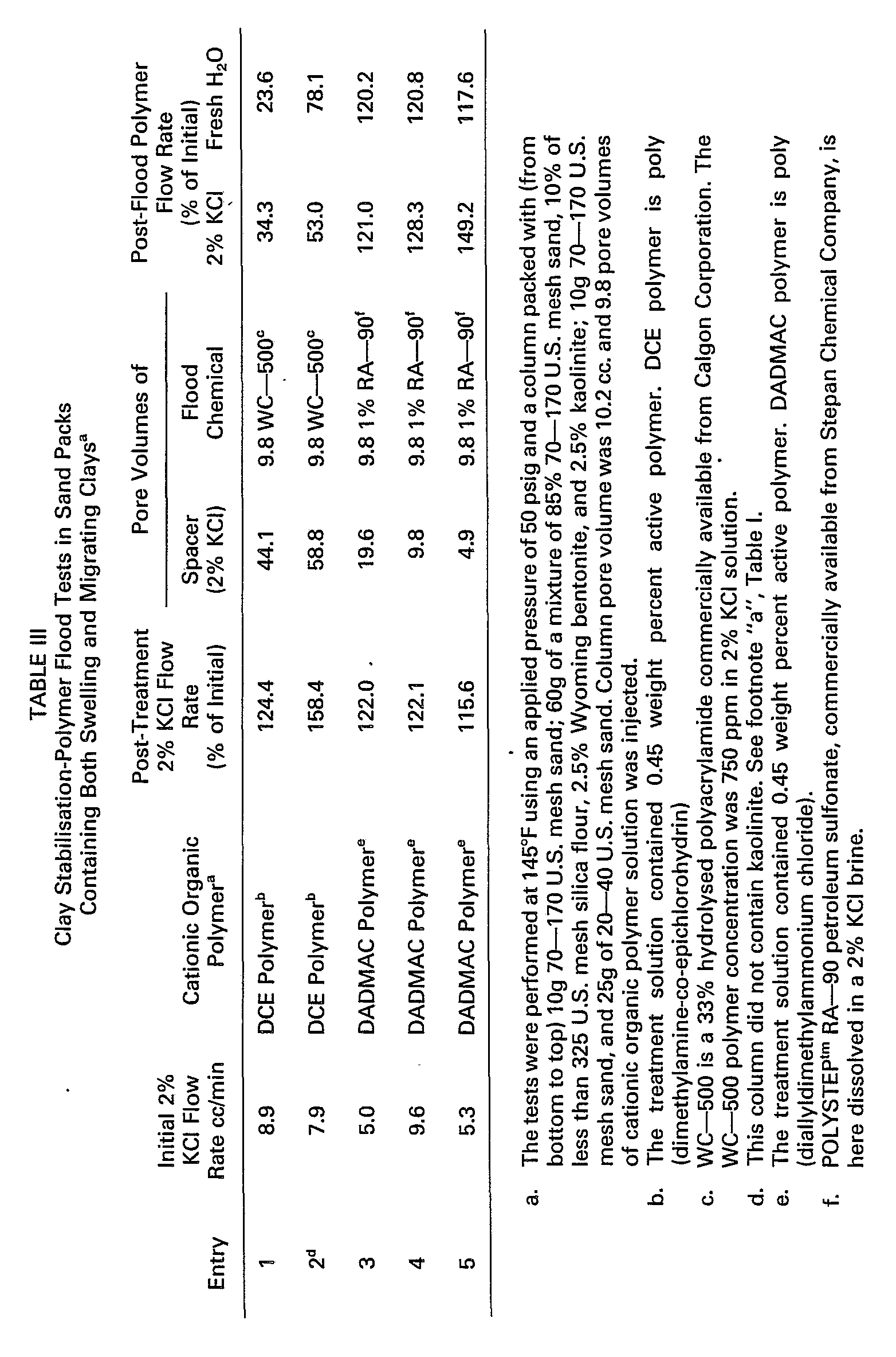
- Table III illustrates experiments that were performed in test columns containing both water-swelling and migrating clays. Instead of 5 weight percent smectite, the unconsolidated test sand contained 2.5% by weight kaolinite and 2.5% by weight smectite. Kaolinite is a migrating clay while smectite is a water-swelling clay. Entry 1 in Table III illustrates a 44.1 pore volume inert spacer fluid injected between the DCE polymer and the WC-500 polymer solution. The flow rate of a 2% potassium chloride solution injected after the WC-500 polymer was only 34.3% of the initial flow rate. The subsequent fresh water flow rate (23.6% of the initial 2% potassium chloride brine flow rate) suggested that the flow rate reduction was due to a physical plugging and not to the slow elution of the viscous flood polymer solution. This interpretation is supported by the results of entry 2. This test column did not contain any kaolinite and a somewhat larger volume (58.8 pore volumes) of inert spacer fluid was used. The 2% potassium chloride flow rate after flood polymer injection was only 53.0% of the initial flow rate. However, the subsequent fresh water flow rate increased to 78.1 % of the initial 2% potassium chloride brine flow rate. This increase in flow rate suggested a slow elution of the viscous flood polymer solution and not a physical plugging phenomenon was responsible for this reduced flow rate. However, in the kaolinite-containing test column (entry 1) the fresh water flow rate was actually less than the preceding 2% potassium chloride brine flow rate, indicating that the flow rates were not due to the slow elution of the flood polymer. Entries 3-5 of Table III study the effects of DADMAC polymer used in conjuction with subsequent injection of a micellar slug, a surfactant/ oil/water emulsion, which would have a low interfacial tension with a crude oil. To simulate the anionic surfactant used in such micellar slugs, a petroleum sulfonate in 2% potassium chloride brine was used. The results indicate that in spite of a substantial decrease in the spacer fluid volume from 19.6 to 9.8 to 4.9 pore volumes, no physical plugging occurred. The fluid rate of the 2% potassium chloride brine injected after the petroleum sulfonate was greater than the original 2% potassium chloride brine flow rate. The subsequent fresh water flow rate was greater than the original brine flow rate in all three experiments indicating that an effective clay stabilization treatment had been accomplished.
- In none of the experiments summarized in Table III was any production of fine particles noted despite the presence of kaolinite, a migrating clay, in the test column. Thus, the increased post-treatment flow rates observed in the last three experiments summarized in Table III were due to effective clay stabilisation and not to an increased column permeability caused by the elution of fine particles.
- In the experiments summarized in Table IV, Berea cores containing approximately 12% clay by weight and Hassler-sleeve chambers were used. These tests were performed in two modes. In the first flow test procedure all treatment fluids were injected at the same end of the core to simulate clay stabilization treatment of an injection well. In the second test mode the flow direction was reversed as the clay stabilization treatment was injected in the opposite end of the Berea core from all other fluids. These tests were intended to model the clay stabilization treatment of production wells prior to polymer breakthrough in an enhanced oil recovery project. The cores were hydrated at ambient temperature (75°F) using 2% potassium chloride brine. The pore volume of the core was determined by placing a known volume of brine in the fluid reservoir and injecting this brine into the dry core and producing 50 cc offluid. The pore volume was the difference between the original brine volume and the sum of the produced fluid and the fluid remaining in the reservoir.
- In entries 1 and 2 of Table IV, the DCE polymer treatment solution was injected in the reverse direction compared to the other fluids. The flow rate of 2% KCI brine injected after the flood polymer was greater than ninety percent of the initial 2% KCI flow rate in both cases. This indicated that physical plugging of the Berea core caused by reaction of the clay stabilizer and the partially hydrolyzed polyacrylamide had not occurred. While there were no major injectivity problems observed in entry 1, injectivity problems observed in the entry 2 flow test prompted acidization of the face of the core through which the inert spacer fluid was being injected. The subsequent increase in 2% KCI brine flow rate suggested that rust particles were gradually and continuously being deposited on the face of the core. This hypothesis was supported by the observation that the subsequent fresh water flow rate was signicantly less than the immediately prior 2% KCI brine flow rate in this. experiment whereas in entry 1, the resultant flow rates were within experimental error. In entry 1 use of a 19.6 pore volume spacer between injection of the DCE polymer treatment solution from one end of the core and the flood polymer from the other resulted in excellent post-flood polymer flow rates. These flow rates were within experimental error of the initial 2% KCI brine flow rate. The inert spacer fluid injected into the opposite end of the column represented the production of formation water prior to flood polymer breakthrough. The much larger spacer volume (102.3 vs. 19.6 pore volumes) used in entry 2 suggested that the slightly decreased post-flood polymer rates were not due to the physical interaction of the cationic organic polymer and the partially hydrolyzed polyacrylamide.
- The last two experiments summarized in Table IV were a study of DCE polymer treatment of an injection well followed by an inert spacer fluid and then by injection of a partially hydrolyzed polyacrylamide. Results were consistent with those obtained in unconsolidated clayey sands (see Table V). In experiment entry 3 use of less than twenty pore volumes of spacer (2% KCI brine) sufficed to give excellent flow rates after polymer injection. The post-flood polymer flow rate of the 2% KCI brine was substantially greater than the original flow rate indicating that no significant amount of physical plugging had occurred. The subsequent fresh water flow rate (greater than the original 2% KCI brine flow rate) confirmed the results and indicated that good clay stabilization was achieved.
- In entry 4, similar results were obtained in a higher permeability (111.2 md vs. 71.6 md for the core used in entry 3) and higher clay content core using a 49.5 pore volume 2% KCI brine spacer. The somewhat lower post-flood polymer flow rates obtained in the 111.2 md Berea core as compared to the rates obtained in the 71.6 md core suggested that the permeability difference in the Berea cores used in entries 1 and 2 could not account for the lower post-flood polymer flow rates obtained in the more permeable column. The significantly higher total clay content (18-19%) core used in entry 4 compared to that used in entry 3 (10-11 %) may account at least in part for the lower post-flood polymer flow rates obtained in the more permeable column. It was somewhat surprising to find that the more permeable column had a higher total clay content. All the clays detected in these two cores were migrating clays.
- Thus, by using an inert spacer fluid containing no anionic chemicals between the cationic organic polymer and a partially hydrolyzed polyacrylamide or a petroleum sulfonate, successful clay stabilization without formation plugging due to reaction of the clay stabilizer and the flood polymer may be achieved. The inert spacer fluid appears to spread the cationic organic polymer out to form a monomolecular layer on the clays. The interaction between the clay and the tightly adsorbed cationic organic polymer is so strong that there is no interaction of the flood polymer and/or petroleum sulfonate with the clay stabilizer, that would otherwise lead to precipitate formation and permeability reduction.
- This process may be used in injection wells prior to injection of anionic flood polymers and/or anionic surfactants. Ifflood chemical injection has already begun and formation permeability damage has occurred clay stabilization treatment in conjuction with acidizing injection wells should be preformed. In this case, the clay stabilization treatment must be preceded by an inert spacer fluid to flush the anionic chemicals from the vicinity of the well bore. An inert spacer fluid must also be used prior to resuming injection of the anionic flood chemicals. Additionally, the clay stabilization treatment may be applied to production wells prior to polymer or surfactant breakthrough. In this case, the formation water being produced functions as a spacer fluid.



- In the use of cationic organic polymers to stabilize clays and formations subject to caustic flooding. Table V, flow tests were performed at 93.5°C using an applied pressure of 3.5 kgf/cm2. The flow tests were conducted in Tefion's-sieeve chambers containing clayey sands having the same composition as those described in Table I and III. The sequence of fluid injection was:
- 1. standard laboratory brine (see Table 5, footnote b for definition of standard brine);
- 2. treatment solution (1 cc clay stabilizer +99 cc of 2% KCI solution);
- 3. standard laboratory brine;
- 4. fresh water (deionized water was used);
- 5. deionized water adjusted to pH 12 using sodium hydroxide;
- 6. fresh water (deionized water was used).
- In the first two entries of Table V, DCE polymer was used. The brine flow rate and the fresh water flow rate after treatment of the column were greater than 100%, indicating that the clay stabilization treatment had not damaged column permeability and that the smectite clay was stabilized to fresh water flow. Entries 3 and 4 used the DADMAC polymer. The post-treatment brine flow rates indicated that significant permeability damage had occurred during the clay stabilization treatment. The reason for this was not understood. Later results (see Table VI) suggested that the corrosive caustic solutions may have been forming rust particles in the fluid reservoir. These particles could have been carried into the Teflon@-sleeve chamber reducing column permeability and flow rate. The use of 2% ammonium chloride treatment solvent was probably not the cause since in entry 5 a post-treatment laboratory brine flow rate greater than the initial brine flow rate was observed. The injection of fresh water after the laboratory brine in entries 3 and 4 indicated that substantial clay stabilization was achieved.
- Given the initial permeability damage obtained in entries 3 and 4, a further test (entry 5) was performed to give a more reliable basis for drawing preliminary conclusions. In this test, the post-treatment brine flow rate was 132.6% of the initial flow rate. The fresh water flow rate was 94.0% of the initial brine flow rate indicating that substantial clay stabilization was obtained. A total of 58.8 pore volumes of standard laboratory brine of fresh water were injected prior to injection of 49 pore volumes of pH 12 sodium hydroxide solution. After further injection of 34.3 pore volumes deionized water, the fresh water flow rate was 27.6% of the initial brine flow rate. Thus, the fresh water flow rate declined to 29.4% of its pre-pH 12 solution treatment value. The flow rate of the pH 12 solution treatment was 92.4% of the initial brine flow rate. Thus, the flow rate decline during injection of the pH 12 solution was minor. The reduction of flow rate occurred only upon fresh water injection. No production of solids was noted. This observation was similar to that noted in entry 2 using DCE polymer. Other than the clay stabilizer used and the greater column permeability in entry 5, the test conditions of entries 2 and 5 were virtually identical. Comparison of the final fresh water flow rates in entries 2 and 5 at approximately the same throughput volume (29.4 and 34.3 pore volumes, respectively) indicated that at the same time inert spacer fluid volume, DCE polymer was less susceptible to base attack than DADMAC polymer.
- Sodium silicate is being increasingly considered as an alternative to sodium hydroxide for use in caustic flooding. It has been reported that in core floods where in situ emulsification occurred, greater improvements in enhanced oil recovery were observed using sodium ortho-silicates than sodium hydroxide. (C. P. Brauer and D. T. Wasan "The Role of Emulsification in Entrainment Phenomena in Alkaline Water Flooding of Heavy Crude Oils", Paper No. INDE-111 presented August 23-28, 1981 at the 182nd American Chemical Society National Meeting, New York, New York).
- Table VI indicates the results of a series of flow experiments utilizing sodium silicate as the alkaline flood chemical. Using a total of 83.3 pore volumes of standard laboratory brine and fresh water as a spacer between injection of the DCE polymer treatment solution in the 4% sodium silicate solution, the subsequent fresh water flow rate was not reduced from its value prior to flood chemical injection.
- The brine and fresh waterflow rate prior to sodium silicate solution injection in entry 1 of Table VI were somewhat low. The post-DCE polymer treatment flow rates obtained in the next two tests illustrated by entries 2 and 3 were also quite low. Examination of the top of the sand used in entry 2 indicated that rust was present. The small rust particles were probably produced by the alkaline flood chemical used in previous experiments. After completion of entry 2, the fluid reservoir was cleaned out, but low flow rates and rust deposition were again observed in entry 3. The valves in flow lines were checked and found to contain mobile rust particles. The post-DCE polymer treatment fresh water flow rate in entry 4 indicated that cleaning the flow line solved this problem.
- The results obtained in experiment 4 indicated that using only fresh water as the spacer (which is often preferable since many alkaline floods use a fresh water preflush to condition the reservoir) and reducing the spacer volume to approximately 40 pore volumes (relative to the treated rock) did not reduce the DCE polymer treatment effectiveness. The fresh water flow rates prior to and after 4% aqueous sodium silicate injection were within experimental error. The crude oil targeted for recovery and caustic flooding is often of relatively high viscosity under reservoir conditions. To assure effective displacement of the oil by the DCE polymer treatment, a compatible surfactant could be included in the treatment or a preflush of xylene or some other hydrocarbon could be used.
- Another cationic organic polymer effective in these tests was poly(methacrylamido-4,8-diaza-4,4,8,8-tetramethyl-6-hydroxy-nonamethylene methochloride), abbreviated MDTHN polymer (see entry 5, Table VI). After introduction of the MDTHN polymer, 39 pore volumes of fresh water followed by the 4% sodium silicate solution was introduced. Subsequent fresh water flow rate was greater than the initial brine flow rate indicating that effective clay stabilization was achieved even after injection of the anionic chemical.
- In certain circumstances it may be desirable to inject the aqueous cationic organic polymer clay stabilizer solution into the petroliferous formation as droplets dispersed in a water-external emulsion. Such circumstances are when the rock formation is so water sensitive that any contact with aqueous fluids prior to or during adsorption of the clay stabilizer onto the clays causes permeability damage and when there is a high saturation of viscous oil around the well bore. In the latter case, it is difficult for a low viscosity aqueous solution to displace the viscous oil to permit the clay stabilier to contact the clays. However, use of an oil-external emulsion is more effective due to the absence of interfacial effects caused by water-crude oil contact.
- The use of oil-external emulsions of aqueous droplets containing DCE polymer (hereinafter referred to as "Oil/DCE polymer") have been found to be effective in caustic flooding applications where there is relatively high viscosity oil. Entry 1 of Table VII illustrates the Oil/DCE polymer solution injected into a column containing both kerosine and brine. The post treatment kerosine and fresh water flow rates were 115.9% and 94.1% respectively. The inert spacer fluid was 39 pore volumes fresh water for a total of 83 pore volumes. The subsequent 1% aqueous sodium hydroxide flow rate was only approximately 42% of the initial brine flow rate. Subsequent fresh water flow rate was only 50.6% of the initial brine flow rate while kerosine flow rate was 116.7% of its initial rate.
- The spacer fluid volume was then reduced to 34.3 pore volumes of kerosine in entry 2. No aqueous spacers were used. The flow rate of the 1% aqueous sodium hydroxide was 63.2% of the initial brine flow rate. Subsequent fresh water flow rate was only 46% of the initial brine flow rate. The final kerosine flow rate was within experimental error of the post-Oil/DCE polymer treatment kerosine flow rates.
- These results indicted that the only circumstances in which Oil/DCE polymer treatment of a well should be considered are wells with high oil saturation in adjacent rock, i.e., new wells or production wells with high oil cuts. In other circumstances, it is preferred that aqueous DCE polymer treatment be used. DCE polymer treatment can optionally contain a non-ionic surfactant.
- From Tables V, VI and VII it can be concluded that DCE polymer treatment was effective in the presence of sodium silicate as well as sodium hydroxide if an adequate volume of inert spacer fluid was injected after the clay stabilizer and prior to flood chemical injection. The DADMAC polymer appeared less effective in clay stabilization than DCE polymer in the presence of hydroxide ion. The use of Oil/DCE polymer in the presence of caustic flooding resulted in excellent retention of sand pack permeability of kerosine, but reduced fresh water flow rates were observed after injection of the Oil/DCE polymer and a 1% sodium hydroxide solution.


- It should be recognized that the amount of inert spacer fluid sufficient to cause the clay stabilization polymer to reorient itself on the clay in such a manner as to cause the polymer to continue to stabilize the clay when said clay is subjected to anionic or caustic flood chemicals, will vary according to formation composition. Areas of concern are formation permeability and hererogeneity of the permeability of the formation rock, the porosity of the formation rock, mineralogy of the formation, type and concentration of the cationic organic polymer clay stabilizer utilized, identity and concentration of the anionic or caustic flood chemical, and the formation temperature. There is no general formula that will illustrate the minimum effective amount of inert spacer fluid volume required for clay stabilization success. The minimum effective amount of inert spacer fluid to be utilised can presently be determined only through laboratory analysis.
- Although particular embodiments of the invention have been described, it will be understood that the invention is not limited thereto, since modifications may be made and will become apparent to those skilled in the art. For example, the spacer fluid injected after the cationic organic polymer clay stabilizer should not contain calcium or magnesium salts. Contact of these salts with sodium hydroxide or sodium carbonate solutions will form calcium hydroxide and calcium carbonate each having a low solubility. Contact of these salts with a partially hydrolyzed polyacrylamide will result in formation of a polymer salt which is of low solubility and is a poor viscosifier. Another example is illustrated where an anionic flood chemical has already been injected. In such case a preflush injection ahead of the cationic organic polymer solution will be required. This will prevent contact of the clay stabilizer with the anionic flood chemical prior to adsorption of the clay stabilizer on the clays.
Claims (16)


Applications Claiming Priority (2)
| Application Number | Priority Date | Filing Date | Title |
|---|---|---|---|
| US369764 | 1982-04-19 | ||
| US06/369,764 US4447342A (en) | 1982-04-19 | 1982-04-19 | Method of clay stabilization in enhanced oil recovery |
Publications (2)
| Publication Number | Publication Date |
|---|---|
| EP0092340A1 EP0092340A1 (en) | 1983-10-26 |
| EP0092340B1 true EP0092340B1 (en) | 1986-07-09 |
Family
ID=23456820
Family Applications (1)
| Application Number | Title | Priority Date | Filing Date |
|---|---|---|---|
| EP83301927A Expired EP0092340B1 (en) | 1982-04-19 | 1983-04-06 | Method of clay stabilisation in enhanced oil recovery |
Country Status (4)
| Country | Link |
|---|---|
| US (1) | US4447342A (en) |
| EP (1) | EP0092340B1 (en) |
| CA (1) | CA1200371A (en) |
| DE (1) | DE3364416D1 (en) |
Families Citing this family (64)
| Publication number | Priority date | Publication date | Assignee | Title |
|---|---|---|---|---|
| US4497596A (en) * | 1983-03-24 | 1985-02-05 | Halliburton Company | Method of minimizing fines migration in a subterranean formation |
| US4558741A (en) * | 1984-02-28 | 1985-12-17 | Halliburton Company | Methods of minimizing fines migration in subterranean formations |
| US4574885A (en) * | 1984-06-27 | 1986-03-11 | Phillips Petroleum Company | Agents for petroleum recovery processes |
| US4536303A (en) * | 1984-08-02 | 1985-08-20 | Halliburton Company | Methods of minimizing fines migration in subterranean formations |
| US4563292A (en) * | 1984-08-02 | 1986-01-07 | Halliburton Company | Methods for stabilizing fines contained in subterranean formations |
| US4536304A (en) * | 1984-09-21 | 1985-08-20 | Halliburton Company | Methods of minimizing fines migration in subterranean formations |
| US4536305A (en) * | 1984-09-21 | 1985-08-20 | Halliburton Company | Methods for stabilizing swelling clays or migrating fines in subterranean formations |
| US4703803A (en) * | 1986-06-24 | 1987-11-03 | Cities Service Oil & Gas Corporation | Composition and method for slowly dissolving siliceous material |
| US4852652A (en) * | 1988-05-24 | 1989-08-01 | Chevron Research Company | Chemical flooding with improved injectivity |
| US5211239A (en) * | 1992-02-13 | 1993-05-18 | Clearwater, Inc. | Method of maintaining subterranean formation permeability and inhibiting clay swelling |
| EP0680504B1 (en) * | 1993-11-19 | 1999-03-10 | Clearwater, Inc. | Method of treating shale and clay in hydrocarbon formation drilling |
| US6502637B2 (en) * | 2000-03-27 | 2003-01-07 | Clearwater, Inc. | Treating shale and clay in hydrocarbon producing formations |
| US6454005B1 (en) | 2001-03-09 | 2002-09-24 | Clearwater, Inc. | Treating shale and clay in hydrocarbon producing formations with combinations of guar and potassium formate |
| US7351680B2 (en) * | 2001-09-19 | 2008-04-01 | Hayes James R | High performance water-based mud system |
| US7028771B2 (en) * | 2002-05-30 | 2006-04-18 | Clearwater International, L.L.C. | Hydrocarbon recovery |
| US7741251B2 (en) | 2002-09-06 | 2010-06-22 | Halliburton Energy Services, Inc. | Compositions and methods of stabilizing subterranean formations containing reactive shales |
| US7091159B2 (en) * | 2002-09-06 | 2006-08-15 | Halliburton Energy Services, Inc. | Compositions for and methods of stabilizing subterranean formations containing clays |
| US7220708B2 (en) * | 2003-02-27 | 2007-05-22 | Halliburton Energy Services, Inc. | Drilling fluid component |
| US8181703B2 (en) | 2003-05-16 | 2012-05-22 | Halliburton Energy Services, Inc. | Method useful for controlling fluid loss in subterranean formations |
| US8278250B2 (en) * | 2003-05-16 | 2012-10-02 | Halliburton Energy Services, Inc. | Methods useful for diverting aqueous fluids in subterranean operations |
| US8631869B2 (en) * | 2003-05-16 | 2014-01-21 | Leopoldo Sierra | Methods useful for controlling fluid loss in subterranean treatments |
| US7759292B2 (en) * | 2003-05-16 | 2010-07-20 | Halliburton Energy Services, Inc. | Methods and compositions for reducing the production of water and stimulating hydrocarbon production from a subterranean formation |
| US7182136B2 (en) | 2003-07-02 | 2007-02-27 | Halliburton Energy Services, Inc. | Methods of reducing water permeability for acidizing a subterranean formation |
| US8251141B2 (en) * | 2003-05-16 | 2012-08-28 | Halliburton Energy Services, Inc. | Methods useful for controlling fluid loss during sand control operations |
| US8962535B2 (en) | 2003-05-16 | 2015-02-24 | Halliburton Energy Services, Inc. | Methods of diverting chelating agents in subterranean treatments |
| US20040229756A1 (en) * | 2003-05-16 | 2004-11-18 | Eoff Larry S. | Method for stimulating hydrocarbon production and reducing the production of water from a subterranean formation |
| US8091638B2 (en) * | 2003-05-16 | 2012-01-10 | Halliburton Energy Services, Inc. | Methods useful for controlling fluid loss in subterranean formations |
| US7117942B2 (en) * | 2004-06-29 | 2006-10-10 | Halliburton Energy Services, Inc. | Methods useful for controlling fluid loss during sand control operations |
| US7563750B2 (en) * | 2004-01-24 | 2009-07-21 | Halliburton Energy Services, Inc. | Methods and compositions for the diversion of aqueous injection fluids in injection operations |
| US7159656B2 (en) * | 2004-02-18 | 2007-01-09 | Halliburton Energy Services, Inc. | Methods of reducing the permeabilities of horizontal well bore sections |
| US7207387B2 (en) * | 2004-04-15 | 2007-04-24 | Halliburton Energy Services, Inc. | Methods and compositions for use with spacer fluids used in subterranean well bores |
| US7114568B2 (en) * | 2004-04-15 | 2006-10-03 | Halliburton Energy Services, Inc. | Hydrophobically modified polymers for a well completion spacer fluid |
| US7216707B2 (en) * | 2004-06-21 | 2007-05-15 | Halliburton Energy Services, Inc. | Cement compositions with improved fluid loss characteristics and methods of cementing using such cement compositions |
| US7398825B2 (en) | 2004-12-03 | 2008-07-15 | Halliburton Energy Services, Inc. | Methods of controlling sand and water production in subterranean zones |
| US20080110624A1 (en) * | 2005-07-15 | 2008-05-15 | Halliburton Energy Services, Inc. | Methods for controlling water and particulate production in subterranean wells |
| US7493957B2 (en) | 2005-07-15 | 2009-02-24 | Halliburton Energy Services, Inc. | Methods for controlling water and sand production in subterranean wells |
| US7441598B2 (en) * | 2005-11-22 | 2008-10-28 | Halliburton Energy Services, Inc. | Methods of stabilizing unconsolidated subterranean formations |
| US7549474B2 (en) * | 2006-05-11 | 2009-06-23 | Halliburton Energy Services, Inc. | Servicing a wellbore with an aqueous based fluid comprising a clay inhibitor |
| US7678743B2 (en) | 2006-09-20 | 2010-03-16 | Halliburton Energy Services, Inc. | Drill-in fluids and associated methods |
| US7678742B2 (en) | 2006-09-20 | 2010-03-16 | Halliburton Energy Services, Inc. | Drill-in fluids and associated methods |
| US7687438B2 (en) | 2006-09-20 | 2010-03-30 | Halliburton Energy Services, Inc. | Drill-in fluids and associated methods |
| US7730950B2 (en) | 2007-01-19 | 2010-06-08 | Halliburton Energy Services, Inc. | Methods for treating intervals of a subterranean formation having variable permeability |
| US7934557B2 (en) | 2007-02-15 | 2011-05-03 | Halliburton Energy Services, Inc. | Methods of completing wells for controlling water and particulate production |
| CN100532493C (en) * | 2007-05-21 | 2009-08-26 | 孙安顺 | Chelating oil-repellent clay stabilizer |
| US7552771B2 (en) * | 2007-11-14 | 2009-06-30 | Halliburton Energy Services, Inc. | Methods to enhance gas production following a relative-permeability-modifier treatment |
| US20090253594A1 (en) * | 2008-04-04 | 2009-10-08 | Halliburton Energy Services, Inc. | Methods for placement of sealant in subterranean intervals |
| US20090308599A1 (en) * | 2008-06-13 | 2009-12-17 | Halliburton Energy Services, Inc. | Method of enhancing treatment fluid placement in shale, clay, and/or coal bed formations |
| US9102865B2 (en) * | 2009-02-16 | 2015-08-11 | Chevron Phillips Chemical Company Lp | Wellbore servicing fluids comprising cationic polymers and methods of using same |
| US7998910B2 (en) | 2009-02-24 | 2011-08-16 | Halliburton Energy Services, Inc. | Treatment fluids comprising relative permeability modifiers and methods of use |
| US8420576B2 (en) * | 2009-08-10 | 2013-04-16 | Halliburton Energy Services, Inc. | Hydrophobically and cationically modified relative permeability modifiers and associated methods |
| EP2622175A1 (en) * | 2010-09-29 | 2013-08-07 | E.I. Du Pont De Nemours And Company | Control of fluid flow during treatment of subterranean sites using well fluid injection |
| US8757261B2 (en) | 2011-05-12 | 2014-06-24 | Halliburton Energy Services, Inc. | Methods and compositions for clay control |
| MX360744B (en) | 2012-02-22 | 2018-11-15 | Grace W R & Co | FUNCTIONALIZED POLYAMINS FOR THE CLAY DAMAGE. |
| CN104271625B (en) | 2012-05-04 | 2017-10-03 | 格雷斯公司 | Method and composition for treating clay and aggregates with clay |
| AR091560A1 (en) | 2012-06-26 | 2015-02-11 | Baker Hughes Inc | METHOD FOR REMOVING INORGANIC SCALES |
| WO2015085149A1 (en) * | 2013-12-06 | 2015-06-11 | Cesi Chemical, Inc. | Additives for use with drilling fluids |
| CN103773328A (en) * | 2013-12-30 | 2014-05-07 | 大庆浩拓化工有限公司 | Clay anti-swelling stabilizer as well as preparation method and application thereof |
| WO2016096502A1 (en) | 2014-12-17 | 2016-06-23 | Basf Se | Method of using cationic polymers comprising imidazolium groups for permanent clay stabilization |
| AU2015375555B2 (en) * | 2015-01-05 | 2018-02-08 | Halliburton Energy Services, Inc. | Dry drilling fluid additives and methods relating thereto |
| CN106281260A (en) * | 2015-06-04 | 2017-01-04 | 中国石油化工股份有限公司 | A kind of clay stabilizer being applicable to mud shale oil and gas development and using method |
| GB2561820B (en) * | 2017-04-06 | 2022-08-17 | Petroliam Nasional Berhad Petronas | Method of consolidating a subterranean formation by particle agglomeration |
| CN109306866B (en) * | 2017-07-28 | 2021-12-24 | 中国石油化工股份有限公司 | Method and system for predicting shale formation pressure trend |
| US11427743B2 (en) | 2020-08-27 | 2022-08-30 | Saudi Arabian Oil Company | Cationic nitrogen-containing heterocycles and their application in wellbore stability |
| US11479710B2 (en) * | 2020-12-16 | 2022-10-25 | Halliburton Energy Services, Inc. | Substituted alkanolamine scale inhibitor |
Family Cites Families (6)
| Publication number | Priority date | Publication date | Assignee | Title |
|---|---|---|---|---|
| US2800962A (en) * | 1954-01-15 | 1957-07-30 | Pan American Petroleum Corp | Surface-active agents in well treating |
| US3710863A (en) * | 1970-12-28 | 1973-01-16 | Mobil Oil Corp | Treatment of formations containing fresh-water swelling clays |
| US3797574A (en) * | 1972-10-27 | 1974-03-19 | Texaco Inc | Miscible oil recovery process |
| US4366071A (en) * | 1976-08-13 | 1982-12-28 | Halliburton Company | Oil well treating method and composition |
| NL7904632A (en) * | 1978-09-28 | 1980-04-01 | Halliburton Co | METHOD FOR MODIFYING THE PROPERTIES OF AN AQUEOUS LIQUID, BRANCHED POLYMERS THAT MAY BE USED THERE, METHOD FOR TREATING PARTICULAR MATERIAL, AND METHOD FOR PREPARING A BRANCHED POLYMER. |
| US4409110A (en) * | 1981-01-06 | 1983-10-11 | Halliburton Company | Enhanced oil displacement processes and compositions |
-
1982
- 1982-04-19 US US06/369,764 patent/US4447342A/en not_active Expired - Fee Related
-
1983
- 1983-03-31 CA CA000424988A patent/CA1200371A/en not_active Expired
- 1983-04-06 DE DE8383301927T patent/DE3364416D1/en not_active Expired
- 1983-04-06 EP EP83301927A patent/EP0092340B1/en not_active Expired
Also Published As
| Publication number | Publication date |
|---|---|
| EP0092340A1 (en) | 1983-10-26 |
| US4447342A (en) | 1984-05-08 |
| CA1200371A (en) | 1986-02-11 |
| DE3364416D1 (en) | 1986-08-14 |
Similar Documents
| Publication | Publication Date | Title |
|---|---|---|
| US4447342A (en) | Method of clay stabilization in enhanced oil recovery | |
| US4136739A (en) | Method for generating hydrofluoric acid in a subterranean formation | |
| US3483923A (en) | Oil recovery using combination oilwetting and acidizing treatments | |
| US4031958A (en) | Plugging of water-producing zones in a subterranean formation | |
| CA1267276A (en) | Acidizing method | |
| US7691790B2 (en) | Composition and process for enhanced oil recovery | |
| US5495891A (en) | Foamed gel employed as a drilling fluid, a lost circulation fluid, or a combined drilling/lost circulation fluid | |
| US4596662A (en) | Compositions for use in drilling, completion and workover fluids | |
| US4607695A (en) | High sweep efficiency steam drive oil recovery method | |
| US4624314A (en) | Modified waterflood technique for enhanced hydrocarbon recovery from argillaceous subterranean reservoirs | |
| US4572297A (en) | Method of formation permeability treatment with alkali metal hydroxide | |
| US4217958A (en) | Sacrificial agents for petroleum recovery processes | |
| US5682951A (en) | Foamed gel completion, workover, and kill fluid | |
| CA2043510A1 (en) | Method for decreasing mobility of dense carbon dioxide in subterranean formations | |
| US4981176A (en) | Method for using foams to improve alkaline flooding oil recovery | |
| US3915230A (en) | Surfactant oil recovery process | |
| US3952806A (en) | Method for altering permeability of a hydrocarbon-containing formation | |
| US3927717A (en) | Secondary recovery process utilizing polyvinylpyrrolidones | |
| US3500921A (en) | Polymer-preceded chemical flood | |
| EP0136773B1 (en) | Composition for cross-linking carboxyl polymers and the use thereof in treating subterranean formations | |
| US4184549A (en) | High conformance oil recovery process | |
| US3749169A (en) | Secondary recovery process | |
| USRE29219E (en) | Surfactant oil recovery process | |
| MXPA05000043A (en) | Self-diverting pre-flush acid for sandstone. | |
| US4210205A (en) | Secondary recovery process |
Legal Events
| Date | Code | Title | Description |
|---|---|---|---|
| PUAI | Public reference made under article 153(3) epc to a published international application that has entered the european phase |
Free format text: ORIGINAL CODE: 0009012 |
|
| AK | Designated contracting states |
Designated state(s): DE FR GB IT NL |
|
| 17P | Request for examination filed |
Effective date: 19840308 |
|
| ITF | It: translation for a ep patent filed | ||
| GRAA | (expected) grant |
Free format text: ORIGINAL CODE: 0009210 |
|
| AK | Designated contracting states |
Kind code of ref document: B1 Designated state(s): DE FR GB IT NL |
|
| REF | Corresponds to: |
Ref document number: 3364416 Country of ref document: DE Date of ref document: 19860814 |
|
| ET | Fr: translation filed | ||
| PLBE | No opposition filed within time limit |
Free format text: ORIGINAL CODE: 0009261 |
|
| STAA | Information on the status of an ep patent application or granted ep patent |
Free format text: STATUS: NO OPPOSITION FILED WITHIN TIME LIMIT |
|
| 26N | No opposition filed | ||
| PGFP | Annual fee paid to national office [announced via postgrant information from national office to epo] |
Ref country code: GB Payment date: 19890331 Year of fee payment: 7 |
|
| PGFP | Annual fee paid to national office [announced via postgrant information from national office to epo] |
Ref country code: FR Payment date: 19890412 Year of fee payment: 7 |
|
| ITTA | It: last paid annual fee | ||
| PGFP | Annual fee paid to national office [announced via postgrant information from national office to epo] |
Ref country code: NL Payment date: 19890430 Year of fee payment: 7 |
|
| PGFP | Annual fee paid to national office [announced via postgrant information from national office to epo] |
Ref country code: DE Payment date: 19890502 Year of fee payment: 7 |
|
| PG25 | Lapsed in a contracting state [announced via postgrant information from national office to epo] |
Ref country code: GB Effective date: 19900406 |
|
| PG25 | Lapsed in a contracting state [announced via postgrant information from national office to epo] |
Ref country code: NL Effective date: 19901101 |
|
| GBPC | Gb: european patent ceased through non-payment of renewal fee | ||
| NLV4 | Nl: lapsed or anulled due to non-payment of the annual fee | ||
| PG25 | Lapsed in a contracting state [announced via postgrant information from national office to epo] |
Ref country code: FR Effective date: 19901228 |
|
| PG25 | Lapsed in a contracting state [announced via postgrant information from national office to epo] |
Ref country code: DE Effective date: 19910101 |
|
| REG | Reference to a national code |
Ref country code: FR Ref legal event code: ST |