EP0089842A2 - Lead acid electric storage cell and a positive electrode therefor - Google Patents
Lead acid electric storage cell and a positive electrode therefor Download PDFInfo
- Publication number
- EP0089842A2 EP0089842A2 EP83301558A EP83301558A EP0089842A2 EP 0089842 A2 EP0089842 A2 EP 0089842A2 EP 83301558 A EP83301558 A EP 83301558A EP 83301558 A EP83301558 A EP 83301558A EP 0089842 A2 EP0089842 A2 EP 0089842A2
- Authority
- EP
- European Patent Office
- Prior art keywords
- lead
- beta
- positive electrode
- lead dioxide
- dioxide
- Prior art date
- Legal status (The legal status is an assumption and is not a legal conclusion. Google has not performed a legal analysis and makes no representation as to the accuracy of the status listed.)
- Granted
Links
Images

Classifications
-
- C—CHEMISTRY; METALLURGY
- C01—INORGANIC CHEMISTRY
- C01G—COMPOUNDS CONTAINING METALS NOT COVERED BY SUBCLASSES C01D OR C01F
- C01G21/00—Compounds of lead
- C01G21/02—Oxides
- C01G21/08—Lead dioxide [PbO2]
-
- H—ELECTRICITY
- H01—ELECTRIC ELEMENTS
- H01M—PROCESSES OR MEANS, e.g. BATTERIES, FOR THE DIRECT CONVERSION OF CHEMICAL ENERGY INTO ELECTRICAL ENERGY
- H01M4/00—Electrodes
- H01M4/02—Electrodes composed of, or comprising, active material
- H01M4/14—Electrodes for lead-acid accumulators
-
- H—ELECTRICITY
- H01—ELECTRIC ELEMENTS
- H01M—PROCESSES OR MEANS, e.g. BATTERIES, FOR THE DIRECT CONVERSION OF CHEMICAL ENERGY INTO ELECTRICAL ENERGY
- H01M4/00—Electrodes
- H01M4/02—Electrodes composed of, or comprising, active material
- H01M4/36—Selection of substances as active materials, active masses, active liquids
- H01M4/48—Selection of substances as active materials, active masses, active liquids of inorganic oxides or hydroxides
- H01M4/56—Selection of substances as active materials, active masses, active liquids of inorganic oxides or hydroxides of lead
-
- Y—GENERAL TAGGING OF NEW TECHNOLOGICAL DEVELOPMENTS; GENERAL TAGGING OF CROSS-SECTIONAL TECHNOLOGIES SPANNING OVER SEVERAL SECTIONS OF THE IPC; TECHNICAL SUBJECTS COVERED BY FORMER USPC CROSS-REFERENCE ART COLLECTIONS [XRACs] AND DIGESTS
- Y02—TECHNOLOGIES OR APPLICATIONS FOR MITIGATION OR ADAPTATION AGAINST CLIMATE CHANGE
- Y02E—REDUCTION OF GREENHOUSE GAS [GHG] EMISSIONS, RELATED TO ENERGY GENERATION, TRANSMISSION OR DISTRIBUTION
- Y02E60/00—Enabling technologies; Technologies with a potential or indirect contribution to GHG emissions mitigation
- Y02E60/10—Energy storage using batteries
Definitions
- This invention relates to a lead acid electric storage iell, and includes a method of manufacturing a positive electrode therefor.
- a method of manufacturing a positive electrode for a lead acid electric storage cell comprises, chemically preparing particulate material comprising beta lead dioxide, and supporting the beta lead dioxide with a carrier therefor adapted to be located in the cell.
- the carrier may comprise a permeable, electrically insulating, tubular container for the beta lead dioxide, into which container a current collecting means extends.
- the carrier may comprise an electrically conductive support structure.
- the beta lead dioxide is manufactured by reacting Pb 3 0 4 with nitric acid in the range 3M to 6M at a temperature between 80°C and 100°C.
- the method may include mixing with the beta lead dioxide a particulate, electrically conductive material inert to the electrochemical reactions inside the cell.
- the beta lead dioxide may be mixed with a binder therefor, the binder preferably comprising polytetrafluoroethylene (hereinafter referred to as "PTFE") but desirably not exceeding 20% by weight of the mixture.
- PTFE polytetrafluoroethylene
- the proportion of beta lead dioxide in the mixture is desirably at least 50% by weight.
- the positive electrode may with some advantage be subjected to an initial relatively short electric charge, to improve the electrical capacity of the positive electrode.
- the invention includes a positive electrode made by the method of the invention, and also includes a lead acid electric storage cell incorporating said positive electrode.
- the lead acid electric storage cell includes a negative electrode manufactured by compacting fine lead metal about a carrier therefor.
- the invention rather surprisingly dispenses with the known electrochemical route for the preparation of lead dioxide, and relies on the chemical preparation of beta lead dioxide.
- This choice is counter to the practice of the lead acid battery art, since this art accepts that chemically produced lead dioxide is electrochemically inert. See for example:
- a positive electrode 10 shown comprises, a conventional lead support grid 14 having a multiplicity of rectangular recesses 16 and to both sides of which (only one is shown in Figure 1) active material 18 has been applied.
- a tab 20 of the support grid 14 provides a terminal for current collection when, as shown in Figure 2, the positive electrode 10 is incorporated in an electric cell 24 having a lead negative electrode 26 and containing sulphuric acid as an electrolyte 28.
- the active material 18 comprises beta lead dioxide mixed with PTFE as an inert binder.
- the active material 18 can be made on the lines suggested by Bagshaw, Clarke, and Halliwell in J. Appl. Chem. (1966) 16, 180, by suspending red lead (60 grammes) in 5M nitric acid (300 ml) at a temperature of between about 80 - 100°C, preferably about 95°C for about 15 minutes, the beta lead dioxide particulate product thereby formed subsequently being filtered and washed with water.
- the beta lead dioxide is then mixed with an aqueous slurry of PTFE, for example ICI "FLUON" Grade GPl, and the mixture pressed about the sides of the support grid 14 to form the positive electrode 10.
- graphite powder for example Hopkins & Williams No. 445000; might be mixed with the beta lead dioxide and PTFE.
- the active material 18 comprised 17 grammes chemically prepared beta lead dioxide, 7 grammes graphite powder, and 10 grammes PTFE. It can be observed that an optimum temperature is reached at about 95°C. In each example the grain size of the beta lead 0 dioxide was of the order of 500A.
- the proportion of the PTFE in the active material 18 may be varied without affecting the discharge capacity of the active material 18 to any significant extent, as shown in Table 3 below. * The active material 18 was shed from the support grid 14 after one complete cycle. However even a relatively low proportion (e.g. 0.2% by weight) of PTFE has been found sufficient to retain the active material 18 on the support grid 14 during cycling.
- the PTFE may be mixed with the beta lead dioxide in an alternative manner, for example:-
- Beta lead dioxide was mixed with about 0.2% by weight of PTFE and the mixture ground together until a fibrillated mass of active material 18 was obtained.
- the fibrillated active material 18 was applied to a support grid 14 to form a positive electrode 10.
- the positive electrode 10 could be discharged for about 20 minutes (e.g. a current of about 5mA/cm 2 of active material 18) and subsequently charged for about 20 minutes (e.g. a current of about 20 mA/cm 2 of active material 18).
- Such a positive electrode 10 has then been found to have a discharge capacity of about 50 mA Hour/gramme of active material 18 (about 26% of the theoretical capacity when discharged at about 10 mA/cm 2 of active material 18).
- the beta lead dioxide may be used in the well known tubular plate (or Ironclad) lead acid electric storage battery - see for example, "Standard Handbook for Electrical Engineers", pp 24-3 and 4, 10th Edition, published by the McGraw-Hill Book Company, and incorporated by reference herein.
- tubular plate battery a plurality of parallel lead alloy current collecting rods integral with a cross-piece project vertically downwards into respective permeable tubular containers filled with lead dioxide to form a positive electrode.
- the tubular containers are usually made from woven glass filaments, or from woven or sintered plastics material, such as Terylene polyester or PTFE.
- the beta lead dioxide prepared by the method of the invention is poured into the annular space between the container wall and the current collecting rod in each tubular container.
- the beta lead dioxide may be made by an alternative chemical route, for example:-
- Beta lead dioxide was prepared by the hydrolysis of lead tetra-acetate (100 grammes) in glacial acetic acid (1 litre) by one litre of water added over about 4 hours, beta lead dioxide precipitate thereby formed being subsequently washed with water and filtered.
- the negative electrode 26 may comprise spongy lead 30, or may be made by compacting fine lead metal such as lead wool about a lead support grid 32. Alternatively, particulate lead might be compacted about the support grid 32.
- the electric cell 24 was discharged and yielded 670 mA hr (about 5% of the theoretical capacity).
- One advantage of the use together of the positive electrode 10 of the invention and of the negative electrode 26 made by compacting fine lead metal, is that it allows the electric cell 24 to be assembled directly in the charged state, so that the electric cell 24 could be ready for immediate use.
Landscapes
- Chemical & Material Sciences (AREA)
- Chemical Kinetics & Catalysis (AREA)
- Electrochemistry (AREA)
- General Chemical & Material Sciences (AREA)
- Inorganic Chemistry (AREA)
- Organic Chemistry (AREA)
- Battery Electrode And Active Subsutance (AREA)
- Investigating Or Analyzing Materials By The Use Of Electric Means (AREA)
- Secondary Cells (AREA)
Abstract
Description
- This invention relates to a lead acid electric storage iell, and includes a method of manufacturing a positive electrode therefor.
- In a well known method of manufacturing a positive electrode for a lead acid electric storage cell, lead monoxide is mixed with water and sulphuric acid to form an active mass which is then pressed into a lead grid. The grid with the active mass is subsequently held in an environment of controlled humidity for 2-3 days - the "curing" process, and then subjected to a low charging current for a further 2-3 days to convert the active mass electrochemically to lead dioxide - the "formation" process. This known method is time consuming and relatively costly, and thus the invention is concerned with providing an alternative, much shorter method of manufacturing the positive electrode.
- According to the present invention, a method of manufacturing a positive electrode for a lead acid electric storage cell comprises, chemically preparing particulate material comprising beta lead dioxide, and supporting the beta lead dioxide with a carrier therefor adapted to be located in the cell.
- The carrier may comprise a permeable, electrically insulating, tubular container for the beta lead dioxide, into which container a current collecting means extends. Alternatively, the carrier may comprise an electrically conductive support structure.
- Preferably, the beta lead dioxide is manufactured by reacting
Pb 304 with nitric acid in the range 3M to 6M at a temperature between 80°C and 100°C. - The method may include mixing with the beta lead dioxide a particulate, electrically conductive material inert to the electrochemical reactions inside the cell. In some applications of the invention the beta lead dioxide may be mixed with a binder therefor, the binder preferably comprising polytetrafluoroethylene (hereinafter referred to as "PTFE") but desirably not exceeding 20% by weight of the mixture. However, the proportion of beta lead dioxide in the mixture is desirably at least 50% by weight.
- The positive electrode may with some advantage be subjected to an initial relatively short electric charge, to improve the electrical capacity of the positive electrode.
- It will be understood that the invention includes a positive electrode made by the method of the invention, and also includes a lead acid electric storage cell incorporating said positive electrode. Advantageously, the lead acid electric storage cell includes a negative electrode manufactured by compacting fine lead metal about a carrier therefor.
- It will be seen from the foregoing, that the invention rather surprisingly dispenses with the known electrochemical route for the preparation of lead dioxide, and relies on the chemical preparation of beta lead dioxide. This choice is counter to the practice of the lead acid battery art, since this art accepts that chemically produced lead dioxide is electrochemically inert. See for example:
- (1) Materials Science and Engineering, 28 (1977) pp 167-199, particularly page 187, "Materials and Mechanisms determining performance of Lead-Acid Storage Batteries", by Jeff Perkins, copyright, Elsevier Sequoia SA. Lausanne.
- (2) Paper entitled "Different Forms of Lead Dioxide" particularly page 3, by A. C. Simon and S. M. Caulder, presented at the ILZRO Battery Research Meeting, Germany, 6 May 1980.
- (3) Journal of the Electrochemical Society
Vol 120, No 11, November 1973, pp 1515-1516, particularly page 1516, article entitled "The Hydrogen-Loss Concept of Battery Failure: The Pb02 Electrode", by S. M. Caulder, J. S. Murray, and A. C. Simon. - (4) Journal of the Electrochemical Society, Vol 122, No 4, April 1975, pp 461-466, particularly page 463, article entitled "Structural Tranformations of the Pb02 Active Material during Cycling" by A. C. Simon, S. M. Caulder, and J. T. Stemmle.
- (5) Journal of Power Sources, 4 (1979) pp 203-213, particularly page 209, copyright, Elsevier Sequoia SA, Lausanne, "Conductivity Measurements on Pure and Mixed Metal Dioxides", by Jean Brenet and Peter Faber.
- (6) Journal of Power Sources, 4 (1979) pp 183-190, particularly page 188, copyright, Elsevier Sequoia SA, Lausanne, "Electrochemical Behaviour of Metallic Oxides", by Jean Brenet.
- However, notwithstanding the consistent practice of the art to the contrary, positive electrodes made by the method of the invention have been found to possess a significant discharge capacity.
- The invention will be further described by way of example only with reference to the accompanying drawings, in which:-
- Figure 1 shows a partly broken away side view of a representation of a positive electrode for a lead acid electric storage cell;
- Figure 2 shows a diagrammatic sectional representation of a lead acid electric storage cell including the positive electrode of Figure 1; and
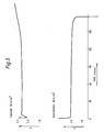
- Figure 3 shows a graphical representation of a charge/discharge cycle of the positive electrode of Figure 1.
- Referring now to Figure 1, a
positive electrode 10 shown comprises, a conventionallead support grid 14 having a multiplicity ofrectangular recesses 16 and to both sides of which (only one is shown in Figure 1)active material 18 has been applied. Atab 20 of thesupport grid 14 provides a terminal for current collection when, as shown in Figure 2, thepositive electrode 10 is incorporated in anelectric cell 24 having a leadnegative electrode 26 and containing sulphuric acid as anelectrolyte 28. - The
active material 18 comprises beta lead dioxide mixed with PTFE as an inert binder. Theactive material 18 can be made on the lines suggested by Bagshaw, Clarke, and Halliwell in J. Appl. Chem. (1966) 16, 180, by suspending red lead (60 grammes) in 5M nitric acid (300 ml) at a temperature of between about 80 - 100°C, preferably about 95°C for about 15 minutes, the beta lead dioxide particulate product thereby formed subsequently being filtered and washed with water. The beta lead dioxide is then mixed with an aqueous slurry of PTFE, for example ICI "FLUON" Grade GPl, and the mixture pressed about the sides of thesupport grid 14 to form thepositive electrode 10. In some applications graphite powder, for example Hopkins & Williams No. 445000; might be mixed with the beta lead dioxide and PTFE. - Some results obtained using
positive electrodes 10 of different compositions are shown in Table 1 below:-
- During subsequent cycling of about 40 deep discharge/charge cycles, the discharge capacities remained substantially constant, and the
active material 18 adhered well to thesupport grid 14. A typical discharge/charge cycle for thepositive electrode 10 is illustrated in Figure 3 to which reference, may be made. - The affect on discharge capacity of varying the temperature of the nitric acid when forming the beta lead dioxide can be seen in Table 2 below:-

- In each of the examples in Table 2, the
active material 18 comprised 17 grammes chemically prepared beta lead dioxide, 7 grammes graphite powder, and 10 grammes PTFE. It can be observed that an optimum temperature is reached at about 95°C. In each example the grain size of thebeta lead 0 dioxide was of the order of 500A. - The proportion of the PTFE in the
active material 18 may be varied without affecting the discharge capacity of theactive material 18 to any significant extent, as shown in Table 3 below.
active material 18 was shed from thesupport grid 14 after one complete cycle. However even a relatively low proportion (e.g. 0.2% by weight) of PTFE has been found sufficient to retain theactive material 18 on thesupport grid 14 during cycling. - Instead of the PTFE being in the form of an aqueous slurry, the PTFE may be mixed with the beta lead dioxide in an alternative manner, for example:-
- Beta lead dioxide was mixed with about 0.2% by weight of PTFE and the mixture ground together until a fibrillated mass of
active material 18 was obtained. The fibrillatedactive material 18 was applied to asupport grid 14 to form apositive electrode 10. Subsequently in thecell 24 thepositive electrode 10 could be discharged for about 20 minutes (e.g. a current of about 5mA/cm2 of active material 18) and subsequently charged for about 20 minutes (e.g. a current of about 20 mA/cm2 of active material 18). Such apositive electrode 10 has then been found to have a discharge capacity of about 50 mA Hour/gramme of active material 18 (about 26% of the theoretical capacity when discharged at about 10 mA/cm2 of active material 18). - As an alternative to mixing the chemically prepared lead dioxide with the PTFE and the graphite powder to form an
active mass 18 to be applied to asupport grid 14, the beta lead dioxide may be used in the well known tubular plate (or Ironclad) lead acid electric storage battery - see for example, "Standard Handbook for Electrical Engineers", pp 24-3 and 4, 10th Edition, published by the McGraw-Hill Book Company, and incorporated by reference herein. In the tubular plate battery, a plurality of parallel lead alloy current collecting rods integral with a cross-piece project vertically downwards into respective permeable tubular containers filled with lead dioxide to form a positive electrode. The tubular containers are usually made from woven glass filaments, or from woven or sintered plastics material, such as Terylene polyester or PTFE. Thus the beta lead dioxide prepared by the method of the invention is poured into the annular space between the container wall and the current collecting rod in each tubular container. - The beta lead dioxide may be made by an alternative chemical route, for example:-
- Beta lead dioxide was prepared by the hydrolysis of lead tetra-acetate (100 grammes) in glacial acetic acid (1 litre) by one litre of water added over about 4 hours, beta lead dioxide precipitate thereby formed being subsequently washed with water and filtered.
- Then 20 grammes of the beta lead dioxide precipitate, 6 grammes graphite powder, and 2.5 ml of an aqueous slurry of PTFE, were mixed with 2.5 ml of water to form an
active mass 18 which was applied to asupport grid 14 of apositive electrode 10. Thepositive electrode 10 subsequently yielded 0.75 Amp hour capacity (i.e. 16.7% of the theoretical capacity) at 0.25 amps. - It has been observed that variations in the discharge capacity of the positive electrode may be influenced by differences in the microstructure of the
active material 18, although subsequent heating of the beta lead dioxide at 200°C does not appear to have any significant affect on discharge capacity. - The
negative electrode 26 may comprisespongy lead 30, or may be made by compacting fine lead metal such as lead wool about alead support grid 32. Alternatively, particulate lead might be compacted about thesupport grid 32. - A comparison made between the lead acid
electric storage cell 24 provided with a conventional commercialnegative electrode 26, and theelectric cell 24 provided with anegative electrode 26 made by compacting fine lead metal, had the following results:- - Positive electrode composition
- Beta lead dioxide - 60 grammes
- Binder - PTFE ∼ 8 grammes
- graphite powder - 14 grammes
- Negative electrode
- Conventional commercial negative electrode
- The
electric cell 24 was discharged and yielded 670 mA hr (about 5% of the theoretical capacity). - This test was repeated with the
negative electrode 26 being replaced by a negative electrode comprising compacted lead wool of the same weight as the lead in the commercial negative electrode. Theelectric cell 24 when discharged yielded 570 mA hr at a rate of 90 mA. - One advantage of the use together of the
positive electrode 10 of the invention and of thenegative electrode 26 made by compacting fine lead metal, is that it allows theelectric cell 24 to be assembled directly in the charged state, so that theelectric cell 24 could be ready for immediate use.
Claims (21)
Applications Claiming Priority (6)
| Application Number | Priority Date | Filing Date | Title |
|---|---|---|---|
| GB8208326 | 1982-03-22 | ||
| GB08208326A GB2117278A (en) | 1982-03-22 | 1982-03-22 | A method of manufacturing a positive electrode for a lead acid electric storage cell |
| GB08222739A GB2117279A (en) | 1982-03-22 | 1982-08-06 | A method of manufacturing a positive electrode for a lead acid electric storage cell |
| GB8222739 | 1982-08-06 | ||
| GB8236203 | 1982-12-20 | ||
| GB8236203 | 1982-12-20 |
Publications (3)
| Publication Number | Publication Date |
|---|---|
| EP0089842A2 true EP0089842A2 (en) | 1983-09-28 |
| EP0089842A3 EP0089842A3 (en) | 1984-12-27 |
| EP0089842B1 EP0089842B1 (en) | 1990-10-03 |
Family
ID=27261525
Family Applications (1)
| Application Number | Title | Priority Date | Filing Date |
|---|---|---|---|
| EP83301558A Expired - Lifetime EP0089842B1 (en) | 1982-03-22 | 1983-03-21 | Lead acid electric storage cell and a positive electrode therefor |
Country Status (4)
| Country | Link |
|---|---|
| EP (1) | EP0089842B1 (en) |
| CA (1) | CA1199059A (en) |
| DE (2) | DE89842T1 (en) |
| GB (1) | GB2124521B (en) |
Cited By (1)
| Publication number | Priority date | Publication date | Assignee | Title |
|---|---|---|---|---|
| EP0120128A1 (en) * | 1983-02-28 | 1984-10-03 | Allied Corporation | Forming of tetrabasic lead sulfate battery electrodes |
Families Citing this family (1)
| Publication number | Priority date | Publication date | Assignee | Title |
|---|---|---|---|---|
| CN112290017B (en) * | 2020-09-14 | 2022-06-14 | 超威电源集团有限公司 | Positive lead paste of lead-acid storage battery, preparation method of positive lead paste and lead-acid storage battery |
Family Cites Families (7)
| Publication number | Priority date | Publication date | Assignee | Title |
|---|---|---|---|---|
| FR544766A (en) * | 1921-09-30 | 1922-09-29 | Accumulator | |
| US2677713A (en) * | 1951-07-13 | 1954-05-04 | Weil Valentin | Cell unit for accumulators and method to produce it |
| GB1307221A (en) * | 1969-01-20 | 1973-02-14 | Bosch Gmbh Robert | Lead plate batteries |
| US3909292A (en) * | 1971-10-27 | 1975-09-30 | Matsushita Electric Industrial Co Ltd | Lead storage battery |
| US4315829A (en) * | 1978-01-27 | 1982-02-16 | Exide Corporation | Method of preparing a battery paste containing fibrous polyfluoroethylene for use in the plates of a lead-acid storage battery |
| DE2827107C3 (en) * | 1978-06-21 | 1981-02-26 | Rheinisch-Westfaelisches Elektrizitaetswerk Ag, 4300 Essen | HOtM 4-56 |
| US4252872A (en) * | 1980-02-14 | 1981-02-24 | Esb Incorporated | Granulated lead oxides with teflon |
-
1983
- 1983-03-21 EP EP83301558A patent/EP0089842B1/en not_active Expired - Lifetime
- 1983-03-21 GB GB08307762A patent/GB2124521B/en not_active Expired
- 1983-03-21 DE DE198383301558T patent/DE89842T1/en active Pending
- 1983-03-21 DE DE8383301558T patent/DE3381915D1/en not_active Expired - Lifetime
- 1983-03-21 CA CA000424027A patent/CA1199059A/en not_active Expired
Cited By (1)
| Publication number | Priority date | Publication date | Assignee | Title |
|---|---|---|---|---|
| EP0120128A1 (en) * | 1983-02-28 | 1984-10-03 | Allied Corporation | Forming of tetrabasic lead sulfate battery electrodes |
Also Published As
| Publication number | Publication date |
|---|---|
| GB2124521A (en) | 1984-02-22 |
| DE3381915D1 (en) | 1990-11-08 |
| EP0089842B1 (en) | 1990-10-03 |
| DE89842T1 (en) | 1984-02-16 |
| GB2124521B (en) | 1985-11-06 |
| CA1199059A (en) | 1986-01-07 |
| EP0089842A3 (en) | 1984-12-27 |
| GB8307762D0 (en) | 1983-04-27 |
Similar Documents
| Publication | Publication Date | Title |
|---|---|---|
| US5017446A (en) | Electrodes containing conductive metal oxides | |
| US5045170A (en) | Electrodies containing a conductive metal oxide | |
| EP0028072B1 (en) | A nickel electrode, a method of producing the nickel electrode and an electrochemical cell employing the nickel electrode | |
| EP0165589A2 (en) | Secondary battery and method of manufacturing the same | |
| US4507855A (en) | Lead acid electric storage cell and a positive electrode therefor | |
| CA2173244A1 (en) | Method of making a rechargeable manganese-oxide compound and related electrode material | |
| EP1801902A2 (en) | Lead acid battery | |
| EP0089842A2 (en) | Lead acid electric storage cell and a positive electrode therefor | |
| US4508147A (en) | Method of manufacturing a positive electrode for a lead acid electric storage cell | |
| JP2993668B2 (en) | Conductive ceramic support for active materials in lead / acid batteries | |
| JP2020515721A (en) | Electrodes for metal ion batteries, and related materials, batteries and methods | |
| US3844838A (en) | Alkaline cells with anodes made from zinc fibers and needles | |
| JPH10302783A (en) | Sealed lead-acid battery and manufacturing method thereof | |
| Sharma et al. | The effect of the amount of electrolyte in the anode gel on the rechargeability of alkaline manganese dioxide zinc cells | |
| JPH0414758A (en) | Lead-acid accumulator | |
| GB2117279A (en) | A method of manufacturing a positive electrode for a lead acid electric storage cell | |
| Taylor et al. | A" Precharged" Positive Plate for the Lead–Acid Automotive Battery: I. Positive Plate Allowing Direct Incorporation of PbO 2 | |
| JP2021086730A (en) | Method for manufacturing positive electrode plate for lead acid battery | |
| JPH04248268A (en) | Electrode of battery | |
| US3905830A (en) | Zinc fibers and needles and process for preparing the same | |
| JP3648761B2 (en) | How to charge sealed lead-acid batteries | |
| JPH0642377B2 (en) | New battery | |
| JP2929894B2 (en) | Manufacturing method of sealed lead-acid battery | |
| Matthews | Electrochemical power sources for electric vehicles | |
| Barak | Lead/acid storage batteries |
Legal Events
| Date | Code | Title | Description |
|---|---|---|---|
| PUAI | Public reference made under article 153(3) epc to a published international application that has entered the european phase |
Free format text: ORIGINAL CODE: 0009012 |
|
| AK | Designated contracting states |
Designated state(s): DE FR GB |
|
| EL | Fr: translation of claims filed | ||
| DET | De: translation of patent claims | ||
| PUAL | Search report despatched |
Free format text: ORIGINAL CODE: 0009013 |
|
| AK | Designated contracting states |
Designated state(s): DE FR GB |
|
| 17P | Request for examination filed |
Effective date: 19850624 |
|
| 17Q | First examination report despatched |
Effective date: 19860128 |
|
| RBV | Designated contracting states (corrected) |
Designated state(s): DE FR |
|
| GRAA | (expected) grant |
Free format text: ORIGINAL CODE: 0009210 |
|
| AK | Designated contracting states |
Kind code of ref document: B1 Designated state(s): DE FR |
|
| ET | Fr: translation filed | ||
| REF | Corresponds to: |
Ref document number: 3381915 Country of ref document: DE Date of ref document: 19901108 |
|
| PGFP | Annual fee paid to national office [announced via postgrant information from national office to epo] |
Ref country code: DE Payment date: 19910227 Year of fee payment: 9 |
|
| PGFP | Annual fee paid to national office [announced via postgrant information from national office to epo] |
Ref country code: FR Payment date: 19910304 Year of fee payment: 9 |
|
| PLBE | No opposition filed within time limit |
Free format text: ORIGINAL CODE: 0009261 |
|
| STAA | Information on the status of an ep patent application or granted ep patent |
Free format text: STATUS: NO OPPOSITION FILED WITHIN TIME LIMIT |
|
| 26N | No opposition filed | ||
| PG25 | Lapsed in a contracting state [announced via postgrant information from national office to epo] |
Ref country code: FR Effective date: 19921130 |
|
| PG25 | Lapsed in a contracting state [announced via postgrant information from national office to epo] |
Ref country code: DE Effective date: 19921201 |
|
| REG | Reference to a national code |
Ref country code: FR Ref legal event code: ST |
|
| APAH | Appeal reference modified |
Free format text: ORIGINAL CODE: EPIDOSCREFNO |