EP0089831A2 - Data communications system ensuring redundant message suppression - Google Patents
Data communications system ensuring redundant message suppression Download PDFInfo
- Publication number
- EP0089831A2 EP0089831A2 EP83301524A EP83301524A EP0089831A2 EP 0089831 A2 EP0089831 A2 EP 0089831A2 EP 83301524 A EP83301524 A EP 83301524A EP 83301524 A EP83301524 A EP 83301524A EP 0089831 A2 EP0089831 A2 EP 0089831A2
- Authority
- EP
- European Patent Office
- Prior art keywords
- message
- sequence number
- message sequence
- receiver
- received
- Prior art date
- Legal status (The legal status is an assumption and is not a legal conclusion. Google has not performed a legal analysis and makes no representation as to the accuracy of the status listed.)
- Withdrawn
Links
Images


Classifications
-
- H—ELECTRICITY
- H04—ELECTRIC COMMUNICATION TECHNIQUE
- H04L—TRANSMISSION OF DIGITAL INFORMATION, e.g. TELEGRAPHIC COMMUNICATION
- H04L1/00—Arrangements for detecting or preventing errors in the information received
- H04L1/12—Arrangements for detecting or preventing errors in the information received by using return channel
- H04L1/16—Arrangements for detecting or preventing errors in the information received by using return channel in which the return channel carries supervisory signals, e.g. repetition request signals
- H04L1/18—Automatic repetition systems, e.g. Van Duuren systems
-
- H—ELECTRICITY
- H04—ELECTRIC COMMUNICATION TECHNIQUE
- H04L—TRANSMISSION OF DIGITAL INFORMATION, e.g. TELEGRAPHIC COMMUNICATION
- H04L1/00—Arrangements for detecting or preventing errors in the information received
- H04L1/12—Arrangements for detecting or preventing errors in the information received by using return channel
- H04L1/16—Arrangements for detecting or preventing errors in the information received by using return channel in which the return channel carries supervisory signals, e.g. repetition request signals
-
- H—ELECTRICITY
- H04—ELECTRIC COMMUNICATION TECHNIQUE
- H04L—TRANSMISSION OF DIGITAL INFORMATION, e.g. TELEGRAPHIC COMMUNICATION
- H04L1/00—Arrangements for detecting or preventing errors in the information received
- H04L1/12—Arrangements for detecting or preventing errors in the information received by using return channel
- H04L2001/125—Arrangements for preventing errors in the return channel
Definitions
- the present invention relates to data communications systems and, more particularly, to a data communications system wherein redundant messages, i.e., messages which have been accurately received before, are suppressed to prevent duplicate control messages from being executed.
- Such verification techniques are normally used in conjunction with receiver "answer back" to the transmitter to indicate receipt of messages by the receiver. Normally, this is accomplished by the receiver transmitting a "Message Received" signal to the transmitter upon verification or attempted verification of the accuracy of a received message.
- the Message Received signal typically is an acknowledgement signal for an accurately received message and an error signal for an inaccurately received message.
- the transmitter Upon receipt of an error signal,. the transmitter retransmits the message corresponding to the error signal, normally the last message transmitted.
- the Message Received or verification signals are typically transmitted from a receiving station to a transmitting station over the same or a separate channel of the same transmission medium over which the original information was sent to the receiving station. Accordingly, the verification signals may also be distorted by the transmission medium and, hence, may be incorrectly received by the transmitter. An incorrect receipt of a verification signal by the transmitter will typically result in a double transmission of a message which has already been correctly received by the receiver. Although it is possible that an error signal could be transmuted into an acknowledgement signal, such transmutation would normally require multiple errors and is relatively unlikely.
- a control message may index a particular piece of apparatus by a given amount from a zero index point. If such a control message is redundantly performed, the relative positioning of the apparatus from the index point is a multiple of the desired displacement actually commanded by the control message.
- Another example is the transmission of a control message to update the quantity of a given item of stock controlled by an inventory system. Such control messages, if redundantly performed, can lead to improper inventory levels with resultant production delays and/or inventory inefficiencies.
- a data communicatons system wherein a receiver suppresses redundant messages which are accurately received by the receiver.
- the system includes a data transmitter which transmits digital messages in a format including a verification portion which permits verification of the accuracy of the transmitted message at the receiver and a message sequence number.
- each message will typically have a message sequence number which is equal to the message sequence number of the last transmitted message plus one. It is noted that the message sequence numbers are repeatedly sequenced through a defined series of numbers so that the highest message sequence number is followed by the lowest message sequence number.
- the receiver maintains a record of the message sequence number of the last accurately received message.
- Each received message is initially verified by means of the verification portion thereof to determine whether it was accurately received or not. If it was not accurately received, an error signal is returned to the transmitter which once again transmits the message. If the message was accurately received, the message sequence number of that message is compared to the message sequence number of the last accurately received message and if the two message sequence numbers are not equal to one another, the accurately received message is stored and the message sequence number of that message is used to update the message sequence number of the last accurately received message.
- an object of the present invention to provide an improved data communications system which , ensures that redundant accurately received messages are suppressed by the receiver.
- Fig. 1 is a functional block diagram of a transmitter and a receiver in accordance with the present invention
- Fig. 2 is a diagram illustrating a typical message format
- Fig. 3 is a block diagram of a microprocessor system incorporating the present invention
- Fig. 4 is a flow diagram of the operation of the system of F ig. 3 for transmitting messages in accordance with the present invention
- Fig. 5 is a flow diagram of the system of Fig. 3 for receiving messages, in accordance with the present invention.
- Fig. 1 is a functional block diagram of a message transmitter on the left and a message receiver on the right in accordance with the present invention.
- a message source 100 generates a data or control message which is passed to an encoder 102 together with an appropriate message sequence number which is contained in a message sequence number storage unit 104.
- the message to be transmitted within the encoder 102 is properly formatted as will be described hereinafter.
- send control logic 106 activates the encoder 102 to transmit the message through a driver 108.
- the message is received by a receiver 110 and passed to a decoder 112 and temporary storage 114.
- the message is verified and the message sequence number is passed on conductors 115 to the input of a message sequence number storage unit 116 which contains the message sequence number of the last accurately received message and to a message sequence number comparator 118.
- the message sequence number comparator 118 receives the message sequence number of the received message from the decoder 112 and the message sequence number of the last accurately received message from the storage unit 116.
- an appropriate signal is passed on a conductor 119 to receiver control logic 120.
- the receiver control logic 120 in turn generates an error signal which is passed through a driver 122 and a receiver 124 to the send control logic 106 of the transmitter.
- the receipt of the error signal causes the transmitter to retransmit the assembled message contained within the encoder 102 to the receiver without updating the message sequence number contained in the storage unit 104.
- an appropriate signal indicating such accurate receipt is passed on the conductor 119 to the receiver control logic 120 and to the message sequence number comparator 118.
- the receiver control logic 120 In response to this signal, the receiver control logic 120 generates an acknowledgement signal which is again passed through the driver 122 and the receiver 124 to the send control logic 106.
- the send control logic 106 increments the message sequence number stored in the storage unit 104 in preparation for transmission of the next message to the receiver. If the acknowledgement signal is erroneously received by the send control logic 106, the message previously sent is retransmitted to the receiver.
- the accurate receipt signal passed to the message sequence number comparator 118 on the conductor 119 causes the comparison of the message sequence number of the accurately received message contained in the decoder 112 and the message sequence number of the last accurately received message contained in the storage unit 116. If the two message sequence numbers are unequal to one another, the message contained in the temporary storage 114 is passed to permanent storage 126 through an electronic switch 128, and the message sequence number of the last accurately received message is stored into the storage unit 116 to update its contents.
- the message sequence number of the accurately received message would have been equal to the message sequence number of the last accurately received message.
- the message sequence number comparator 118 upon detecting this equality does not pass the message from temporary storage 114 to permanent storage 126, nor does it bother to restore the message sequence number in the storage unit 116.
- Fig. 2 is a diagram illustrating a typical message format for use in a data communications system in accordance with the present invention.
- the message 200 to be transmitted comprises a variable number of characters and is preceded by a synchronization character 202 and terminated by a message terminator character 204.
- the receiving station looks for the synchronization character 202 before accepting any data.
- a byte count character 206 informs the receiving station of the number of characters contained in the message 200 thereby locating a checksum character 208 and the end of the message. Use of the byte count prevents misinterpretation of data characters as control codes.
- the byte count includes a message sequence number 210, the message characters 200 and the checksum 208.
- the message sequence number 210 is controlled by the transmitter.
- the message sequence number prevents the receiver from accepting and using a message more than one time if transmission conditions have necessitated retransmission of the message.
- Each new message sent must have the message sequence number incremented from the value of the preceding message. If the transmitter repeats a message due to transmission errors, it must send the identical message not incrementing the message sequence number.
- Each message character includes a parity bit so that the accuracy of the message is verified by such parity as well as the checksum 208.
- the receiver Upon receipt of any message with valid parity and checksum, the receiver compares its message sequence number with the message sequence number of the last accurately received message, and if they are different, the message is sent on to be used by the receiver. If the message sequence numbers are identical, the message is ignored.
- the checksum 208 is calculated across the entire message block including the byte count 206, the message sequence number 210, the message characters 200 and the checksum 208 itself, creating a longitudinal check of total message integrity.
- the checksum is generated by performing an addition of all characters in the message.
- the sending station performs-a two's complement on the checksum before transmitting it and, accordingly, the contents of a receiver checksum adder is equal to 0 for a good transmission.
- a microprocessor control system which may be used, for example, in a manufacturing process.
- the microprocessor system shown may comprise a primary control station in that it oversees a number of other secondary stations each of which similarly comprises a microprocessor system as shown in Fig 3."
- the secondary stations may be used to control individual machines, such as forms printing presses, and each secondary station communicates with the primary station to transmit data relevant to the operation of the controlled machine and to receive operating instructions from the primary station. Accordingly, each microprocessor system, as shown in Fig. 3, functions both as a data transmitter and as a data receiver.
- a microprocessor 300 communicates with a read only memory (ROM) 302, a random access memory (RAM) 304, and an input/output select decoder 306 by means of an address bus 308.
- the ROM 302 contains program instructions for the operation of the microprocessor 300
- the RAM 304 contains data required by the microprocessor 300 and provides storage space for microprocessor operations.
- a data bus 310 is connected to the ROM 302, the RAM 304 and a communications interface adapter 312.
- Program instructions read from the ROM 302 are passed to the microprocessor 300 by means of the data bus 310.
- the RAM 304 and the communications interface adapter 312 are controlled by the microprocessor 300 via a control bus 314 to receive data from the data bus 310 or provide data to the data bus 310 dependent upon the control signals.
- Fig. 1 Data is transmitted to one or more interfacing microprocessor systems from the communication interface adaptor 312 through a driver 316. Similarly, data is received from any interfacing microprocessor system through a receiver 318.
- Fig. 1 and the message format of Fig. 2 provide for communications between two microprocessor systems, as shown in Fig. 3, rather than multiple microprocessor systems. This is for simplicity's sake and ease of description.
- addressing schemes For communications between multiply connected systems, one of a variety of well-known addressing schemes would be incorporated into each system and include addressing bits within the message format of Fig. 2.
- Typical components for constructing the microprocessor system shown in Fig. 3 are listed in the following table:
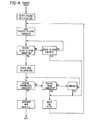
- Fig. 4 illustrates the steps taken for transmission of a message from the system shown in Fig. 3.
- the major steps performed for transmission are also listed chronologically below.
- an output message to be transmitted is assembled to include a data or control message, a verification portion and a message sequence number.
- the format of this message can be as previously described with reference to Fig. 2 for transmission between two systems. If multiple systems are connected to communicate with one another, multiple records must be maintained as to the message sequence numbers to be used for each of the systems when receiving messages and appropriate addressing schemes must be included as previously mentioned.
- a request-to-send character is transmitted to the receiver to which a message is to be transmitted.
- the request-to-send character alerts the receiver that a message is to be sent to it and allows the receiver to prepare for receipt of the message.
- the transmitter waits to receive a clear-to-send character from the receiver. If a clear-to-send character is not received within a given timeout period, the request-to-send character is again transmitted to the receiver in a reattempt to send the message.
- the assembled output message is transmitted to the receiver.
- the transmitter then waits to receive a signal indicating that the transmitted message was received. If the message was accurately received, an acknowledge signal is received; and, if the message was inaccurately received, an error signal is received. If no receipt verification signal is received within a given timeout period, the message is retransmitted. A retransmission of the message also occurs if an error signal is received.
- the message sequence number is incremented by one and the transmission sequence is exited.
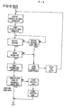
- Fig. 5 illustrates the steps taken for receipt of a message by the system shown in Fig. 3.
- the major steps performed for receipt are also listed chronologically below.
- a receiving system receives a request-to-send character from a transmitting system. Once the receiving system is ready to accept the message, a clear-to-send character is sent to the transmitting system. The receiving system then waits for the message. If a message is not received within a defined timeout period, an error signal is sent to the transmitter and the receiver sets up for a retry of the transmission.
- the verification portion of the message is processed to determine the accuracy of the received message. If an error is detected, the receiver sends an error signal to the transmitter and sets up for retry of transmission as previously described.
- an acknowledgement signal is sent to the transmitter to indicate accurate reception of the message.
- the message sequence number of the accurately received message is compared to the message sequence number of the last message to be accurately received. If the message sequence number of the accurately received message is not equal to the message sequence number of the last accurately received message (which is the normal situation), the message sequence number is updated to equal the message sequence number of the accurately received message, and the accurately received message is stored for utilization by the receiver.
Abstract
A data communications system includes a transmitter (100-108) for transmitting messages, each of which include message characters, a verification portion and a message sequence number. The message sequence number for each message differs from the message preceding it. A receiver (110-122) includes means for verifying the accuracy of the received message and for returning to the transmitter a signal which is either an acknowledgement signal, if the message is inaccurately received, or an error signal, if the message is inaccurately received. To prevent the utilization by the receiver of redundantly received messages, which might occur if the acknowledgement signal is incorrectly received atthe transmitter, the receiver includes means (118) for comparing the message sequence number with the message sequence number of the last accurately received message (116) and for storing (126) the message only if the message sequence numbers are different.
Description
- The present invention relates to data communications systems and, more particularly, to a data communications system wherein redundant messages, i.e., messages which have been accurately received before, are suppressed to prevent duplicate control messages from being executed.
- Whenever information is transmitted from one location to another, the possibility of errors being introduced into the information by the transmission medium is present. Even relatively shortlived interference in the transmission medium can destroy one or more digital bits where the information is transmitted in binary or digital form. The consequences of such errors in transmitted digital data messages are apparent in that a given data message may be transformed into another data message by such errors. Although the possibility of converting one control message into another control message is less likely, errors in the transmission of control messages can also be significant.
- accordingly, it is common in the data communications, art to transmit binary information in the form of blocks of characters and include within those blocks signals for verifying the accuracy of the digital information. For example, a parity check bit or bits and/or a checksum may be included within a block of transmitted digital data. Also, other coding arrangements as well as timeouts, all well known in the art, may be utilized to ensure the accurate transmission of digital messages.
- Such verification techniques are normally used in conjunction with receiver "answer back" to the transmitter to indicate receipt of messages by the receiver. Normally, this is accomplished by the receiver transmitting a "Message Received" signal to the transmitter upon verification or attempted verification of the accuracy of a received message. The Message Received signal typically is an acknowledgement signal for an accurately received message and an error signal for an inaccurately received message. Upon receipt of an error signal,. the transmitter retransmits the message corresponding to the error signal, normally the last message transmitted.
- The Message Received or verification signals are typically transmitted from a receiving station to a transmitting station over the same or a separate channel of the same transmission medium over which the original information was sent to the receiving station. Accordingly, the verification signals may also be distorted by the transmission medium and, hence, may be incorrectly received by the transmitter. An incorrect receipt of a verification signal by the transmitter will typically result in a double transmission of a message which has already been correctly received by the receiver. Although it is possible that an error signal could be transmuted into an acknowledgement signal, such transmutation would normally require multiple errors and is relatively unlikely.
- While the possibility of converting one control message into another due to transmission errors is unlikely, the possibility of retransmission of a control message due to transmission errors in the acknowledgement signal is much higher. In many applications, it is very important that such redundantly transmitted control messages are not also redundantly performed at the receiving station.
- For example, in a machine control system, a control message may index a particular piece of apparatus by a given amount from a zero index point. If such a control message is redundantly performed, the relative positioning of the apparatus from the index point is a multiple of the desired displacement actually commanded by the control message. Another example is the transmission of a control message to update the quantity of a given item of stock controlled by an inventory system. Such control messages, if redundantly performed, can lead to improper inventory levels with resultant production delays and/or inventory inefficiencies.
- According to one aspect of the present invention, a data communicatons system is provided wherein a receiver suppresses redundant messages which are accurately received by the receiver. The system includes a data transmitter which transmits digital messages in a format including a verification portion which permits verification of the accuracy of the transmitted message at the receiver and a message sequence number.
- The message sequence numbers for consecutive messages transmitted by the transmitter are sequentially incremented. Thus, each message will typically have a message sequence number which is equal to the message sequence number of the last transmitted message plus one. It is noted that the message sequence numbers are repeatedly sequenced through a defined series of numbers so that the highest message sequence number is followed by the lowest message sequence number.
- To prevent the utilization of a redundantly received message, the receiver maintains a record of the message sequence number of the last accurately received message. Each received message is initially verified by means of the verification portion thereof to determine whether it was accurately received or not. If it was not accurately received, an error signal is returned to the transmitter which once again transmits the message. If the message was accurately received, the message sequence number of that message is compared to the message sequence number of the last accurately received message and if the two message sequence numbers are not equal to one another, the accurately received message is stored and the message sequence number of that message is used to update the message sequence number of the last accurately received message.
- It is, therefore, an object of the present invention to provide an improved data communications system which , ensures that redundant accurately received messages are suppressed by the receiver.
- It is another object of the present invention to provide an improved data communications system wherein each transmitted message includes a message sequence number which differs from the message sequence number included in messages transmitted immediately before and after the given message.
- It is yet another object of the present invention to provide an improved data communications system wherein a data receiver maintains a record of the message sequence number of the last accurately received message and will accept a subsequent accurately received message only if its message sequence number differs from the message sequence number of the last accurately received message to ensure that redundant messages are not utilized by the receiver.
- Other objects and advantages of the invention will be apparent from the following description, the accompanying drawings and the appended claims.
- In order that the invention may be more readily understood, reference will now be made to the accompanying drawings, in which: Fig. 1 is a functional block diagram of a transmitter and a receiver in accordance with the present invention, Fig. 2 is a diagram illustrating a typical message format, Fig. 3 is a block diagram of a microprocessor system incorporating the present invention, Fig. 4 is a flow diagram of the operation of the system of Fig. 3 for transmitting messages in accordance with the present invention, Fig. 5 is a flow diagram of the system of Fig. 3 for receiving messages, in accordance with the present invention.
- Fig. 1 is a functional block diagram of a message transmitter on the left and a message receiver on the right in accordance with the present invention. A message source 100 generates a data or control message which is passed to an
encoder 102 together with an appropriate message sequence number which is contained in a message sequencenumber storage unit 104. The message to be transmitted within theencoder 102 is properly formatted as will be described hereinafter. - Upon stable assembly of the message to be transmitted in the
encoder 102, sendcontrol logic 106 activates theencoder 102 to transmit the message through adriver 108. - The message is received by a
receiver 110 and passed to adecoder 112 andtemporary storage 114. In thedecoder 112, the message is verified and the message sequence number is passed onconductors 115 to the input of a message sequencenumber storage unit 116 which contains the message sequence number of the last accurately received message and to a messagesequence number comparator 118. The messagesequence number comparator 118 receives the message sequence number of the received message from thedecoder 112 and the message sequence number of the last accurately received message from thestorage unit 116. - If the message fails to be verified, i.e., is erroneously received and contained in the
decoder 112 and the temporary storage l14, an appropriate signal is passed on aconductor 119 toreceiver control logic 120. Thereceiver control logic 120 in turn generates an error signal which is passed through adriver 122 and areceiver 124 to thesend control logic 106 of the transmitter. The receipt of the error signal causes the transmitter to retransmit the assembled message contained within theencoder 102 to the receiver without updating the message sequence number contained in thestorage unit 104. - On the other hand, if the message was accurately received and verified, an appropriate signal indicating such accurate receipt is passed on the
conductor 119 to thereceiver control logic 120 and to the messagesequence number comparator 118. In response to this signal, thereceiver control logic 120 generates an acknowledgement signal which is again passed through thedriver 122 and thereceiver 124 to thesend control logic 106. In response to the acknowledgement signal, thesend control logic 106 increments the message sequence number stored in thestorage unit 104 in preparation for transmission of the next message to the receiver. If the acknowledgement signal is erroneously received by thesend control logic 106, the message previously sent is retransmitted to the receiver. - The accurate receipt signal passed to the message
sequence number comparator 118 on theconductor 119 causes the comparison of the message sequence number of the accurately received message contained in thedecoder 112 and the message sequence number of the last accurately received message contained in thestorage unit 116. If the two message sequence numbers are unequal to one another, the message contained in thetemporary storage 114 is passed to permanent storage 126 through anelectronic switch 128, and the message sequence number of the last accurately received message is stored into thestorage unit 116 to update its contents. - In the event that the acknowledgement signal was not accurately received by the transmitter and the message was once again transmitted to the receiver, the message sequence number of the accurately received message would have been equal to the message sequence number of the last accurately received message. The message
sequence number comparator 118 upon detecting this equality does not pass the message fromtemporary storage 114 to permanent storage 126, nor does it bother to restore the message sequence number in thestorage unit 116. - Fig. 2 is a diagram illustrating a typical message format for use in a data communications system in accordance with the present invention. The
message 200 to be transmitted comprises a variable number of characters and is preceded by asynchronization character 202 and terminated by amessage terminator character 204. The receiving station looks for thesynchronization character 202 before accepting any data. - A
byte count character 206 informs the receiving station of the number of characters contained in themessage 200 thereby locating achecksum character 208 and the end of the message. Use of the byte count prevents misinterpretation of data characters as control codes. The byte count includes amessage sequence number 210, themessage characters 200 and thechecksum 208. - The
message sequence number 210 is controlled by the transmitter. The message sequence number prevents the receiver from accepting and using a message more than one time if transmission conditions have necessitated retransmission of the message. Each new message sent must have the message sequence number incremented from the value of the preceding message. If the transmitter repeats a message due to transmission errors, it must send the identical message not incrementing the message sequence number. - Each message character includes a parity bit so that the accuracy of the message is verified by such parity as well as the
checksum 208. Upon receipt of any message with valid parity and checksum, the receiver compares its message sequence number with the message sequence number of the last accurately received message, and if they are different, the message is sent on to be used by the receiver. If the message sequence numbers are identical, the message is ignored. - The
checksum 208 is calculated across the entire message block including thebyte count 206, themessage sequence number 210, themessage characters 200 and thechecksum 208 itself, creating a longitudinal check of total message integrity. The checksum is generated by performing an addition of all characters in the message. The sending station performs-a two's complement on the checksum before transmitting it and, accordingly, the contents of a receiver checksum adder is equal to 0 for a good transmission. - It is to be noted that the described message verification techniques are only illustrative and that a large variety of message verification techniques are available for use in accordance with the present invention.
- With reference to Fig. 3, a microprocessor control system is disclosed which may be used, for example, in a manufacturing process. The microprocessor system shown may comprise a primary control station in that it oversees a number of other secondary stations each of which similarly comprises a microprocessor system as shown in Fig 3."
- The secondary stations may be used to control individual machines, such as forms printing presses, and each secondary station communicates with the primary station to transmit data relevant to the operation of the controlled machine and to receive operating instructions from the primary station. Accordingly, each microprocessor system, as shown in Fig. 3, functions both as a data transmitter and as a data receiver.
- A
microprocessor 300 communicates with a read only memory (ROM) 302, a random access memory (RAM) 304, and an input/outputselect decoder 306 by means of anaddress bus 308. TheROM 302 contains program instructions for the operation of themicroprocessor 300, while theRAM 304 contains data required by themicroprocessor 300 and provides storage space for microprocessor operations. - A
data bus 310 is connected to theROM 302, theRAM 304 and acommunications interface adapter 312. Program instructions read from theROM 302 are passed to themicroprocessor 300 by means of thedata bus 310. TheRAM 304 and thecommunications interface adapter 312 are controlled by themicroprocessor 300 via acontrol bus 314 to receive data from thedata bus 310 or provide data to thedata bus 310 dependent upon the control signals. - Data is transmitted to one or more interfacing microprocessor systems from the
communication interface adaptor 312 through adriver 316. Similarly, data is received from any interfacing microprocessor system through areceiver 318. It is noted that the block diagram of Fig. 1 and the message format of Fig. 2 provide for communications between two microprocessor systems, as shown in Fig. 3, rather than multiple microprocessor systems. This is for simplicity's sake and ease of description. For communications between multiply connected systems, one of a variety of well-known addressing schemes would be incorporated into each system and include addressing bits within the message format of Fig. 2. - Typical components for constructing the microprocessor system shown in Fig. 3 are listed in the following table:


- Reference is now made to the flow diagram of Fig. 4 which illustrates the steps taken for transmission of a message from the system shown in Fig. 3. The major steps performed for transmission are also listed chronologically below.
- First, an output message to be transmitted is assembled to include a data or control message, a verification portion and a message sequence number. The format of this message can be as previously described with reference to Fig. 2 for transmission between two systems. If multiple systems are connected to communicate with one another, multiple records must be maintained as to the message sequence numbers to be used for each of the systems when receiving messages and appropriate addressing schemes must be included as previously mentioned.
- To initialize the communications channel prior to transmission, a request-to-send character is transmitted to the receiver to which a message is to be transmitted. The request-to-send character alerts the receiver that a message is to be sent to it and allows the receiver to prepare for receipt of the message. To that end, the transmitter waits to receive a clear-to-send character from the receiver. If a clear-to-send character is not received within a given timeout period, the request-to-send character is again transmitted to the receiver in a reattempt to send the message.
- Once a clear-to-send character has been received by the transmitter, the assembled output message is transmitted to the receiver. The transmitter then waits to receive a signal indicating that the transmitted message was received. If the message was accurately received, an acknowledge signal is received; and, if the message was inaccurately received, an error signal is received. If no receipt verification signal is received within a given timeout period, the message is retransmitted. A retransmission of the message also occurs if an error signal is received.
- If an acknowledge signal is received indicating that the transmitted message was accurately received, the message sequence number is incremented by one and the transmission sequence is exited.
- Reference is now made to the flow diagram of Fig. 5 which illustrates the steps taken for receipt of a message by the system shown in Fig. 3. The major steps performed for receipt are also listed chronologically below.
- First, a receiving system receives a request-to-send character from a transmitting system. Once the receiving system is ready to accept the message, a clear-to-send character is sent to the transmitting system. The receiving system then waits for the message. If a message is not received within a defined timeout period, an error signal is sent to the transmitter and the receiver sets up for a retry of the transmission.
- If a message is received by the receiver, the verification portion of the message is processed to determine the accuracy of the received message. If an error is detected, the receiver sends an error signal to the transmitter and sets up for retry of transmission as previously described.
- If no errors are detected in the received message, an acknowledgement signal is sent to the transmitter to indicate accurate reception of the message. The message sequence number of the accurately received message is compared to the message sequence number of the last message to be accurately received. If the message sequence number of the accurately received message is not equal to the message sequence number of the last accurately received message (which is the normal situation), the message sequence number is updated to equal the message sequence number of the accurately received message, and the accurately received message is stored for utilization by the receiver.
- In the event the message sequence numbers are equal to one another, the received message is not recorded. In this way, redundantly received messages,even though accurate, are discarded so that redundant operations are not performed in response to such multiply received messages.
- A listing of the portion of the program used in an MC6809 microprocessor to accomplish the operations as depicted in Figs. 4 and 5 and as described above is set forth as follows:


- While the method herein described and the form of apparatus for carrying this method into effect constitute preferred embodiments of this invention, it is to be understood that the invention is not limited to this precise method and form of apparatus and that changes may be made in either without departing from the scope of the invention which is defined in the appended claims as defined in the appended claims.
Claims (7)
1. A method of communication between a data transmitter and a data receiver comprising the steps of:
a) transmitting a message from said transmitter to said receiver;
b) including a message sequence number within each message transmitted with the message sequence number for different sequentially transmitted messages differing from one another;
c) receiving said message at said receiver;
d) determining the accuracy of said message received at said receiver;
e) acknowledging receipt of each accurately received message by sending an acknowledge signal to said transmitter; .
f) retransmitting a message from said transmitter upon failure to receive an acknowledge signal from said receiver; and
g) accepting an accurately received message at said receiver only if the message sequence number is different from the message sequence number of the last message accurately received at said receiver.
2. The method as claimed in claim 1 further comprising the steps of:
h) acknowledging the receipt of erroneously received messages by sending an error signal to said transmitter; and;
i) retransmitting the last transmitted message from said transmitter including the same message sequence number in response to receipt of an error signal.
3. The method as claimed in claim 2 further comprising the step of incrementing the message sequence number in said transmitter in response to receipt of an acknowledgement signal.
2 or 3, 4. The method as claimed in claim 1, wherein step g) comprises the steps of:
h) maintaining the message sequence number of the last message accurately received from said transmitter;
i) comparing the message sequence number of an accurately received message with the message sequence number of the last accurately received message;
j) storing the accurately received message only if its message sequence number is different from the message sequence number of the last accurately received message; and
k) storing the message sequence number of a message stored in accordance with step j) as the message sequence number of the last accurately received message.
5. A data communications system comprising in combination, a transmitter (100-108) for transmitting messages which include message sequence numbers (210) wherein the message sequence number for each message differs from the message sequence number of the message preceding it and the message sequence number of the message succeeding it, and a' receiver (110-122) for discriminating between newly received and previously received data messages comprising means for verifying the accuracy of received data messages, characterized in that said receiver includes means (118) for identifying the message sequence number contained in the received data messages and means (126) for accepting a verified message only if the message sequence number of said verified message is different from the message sequence number of the last verified message accepted by said receiver.
6. The data communications system as claimed in claim 5,wherein messages including a verification portion (208) and a message sequence number (210) are transmitted, and wherein said receiver comprises:
decoder means (112) for receiving and decoding said messages to determine the accuracy of receipt and to identify the message sequence numbers of said messages;
storage means (llb, 126) for storing accurately received messages and the message sequence number of the last accurately received message; and
comparator means (118) connected to said decoder means and said storage means for comparing the message sequence number of an accurately received message with the message sequence number of the last accurately received message and means (128) for activating said storage means to store said accurately received message and its message sequence number if the compared message sequence numbers are not equal to one another.
7. The system as claimed in claim 6-wherein the receiver comprises message receipt indicating means (120, 122) for returning an acknowledgement signal to said transmitter upon accurate receipt of a message and an error signal upon inaccurate receipt of a message so that erroneously received messages can be retransmitted to said receiver.
Applications Claiming Priority (2)
| Application Number | Priority Date | Filing Date | Title |
|---|---|---|---|
| US35996782A | 1982-03-19 | 1982-03-19 | |
| US359967 | 1982-03-19 |
Publications (2)
| Publication Number | Publication Date |
|---|---|
| EP0089831A2 true EP0089831A2 (en) | 1983-09-28 |
| EP0089831A3 EP0089831A3 (en) | 1985-05-22 |
Family
ID=23416020
Family Applications (1)
| Application Number | Title | Priority Date | Filing Date |
|---|---|---|---|
| EP83301524A Withdrawn EP0089831A3 (en) | 1982-03-19 | 1983-03-18 | Data communications system ensuring redundant message suppression |
Country Status (1)
| Country | Link |
|---|---|
| EP (1) | EP0089831A3 (en) |
Cited By (11)
| Publication number | Priority date | Publication date | Assignee | Title |
|---|---|---|---|---|
| EP0213682A2 (en) * | 1985-09-04 | 1987-03-11 | Philips Electronics Uk Limited | Method of, and apparatus for data communication |
| GB2181924A (en) * | 1985-09-10 | 1987-04-29 | Hasselblad Ab Victor | A device for long-distance transmission of images |
| EP0393117A1 (en) * | 1987-11-10 | 1990-10-24 | Echelon Systems | Protocol for network having a plurality of intelligent cells. |
| EP0473869A1 (en) * | 1990-08-28 | 1992-03-11 | Landis & Gyr Business Support AG | Method of automatic reemission of a message after reception with errors |
| US6151627A (en) * | 1998-03-25 | 2000-11-21 | 3Com Technologies | Monitoring of a communication link utilizing history-based compression algorithms |
| WO2002033981A2 (en) * | 2000-10-17 | 2002-04-25 | Kent Ridge Digital Labs | Method for eliminating and identifying redundant message information |
| WO2003007530A2 (en) * | 2001-07-10 | 2003-01-23 | Koninklijke Philips Electronics N.V. | Method of transmitting data packets |
| US7096391B2 (en) * | 2003-04-29 | 2006-08-22 | Hewlett-Packard Development Company, L.P. | Error message suppression system and method |
| CN1298132C (en) * | 2003-05-16 | 2007-01-31 | 株式会社Ntt都科摩 | Receiving device, transmitting device, and programs |
| US7412252B2 (en) | 2002-05-15 | 2008-08-12 | Ipwireless, Inc. | System, transmitter, receiver and method for communication power control |
| KR101161040B1 (en) * | 2004-04-29 | 2012-06-28 | 에꼴 뽈리떼끄닉 뻬데랄 드 로잔느 (으뻬에프엘) | Heat sink made from a diamond/copper composite material containing boron |
-
1983
- 1983-03-18 EP EP83301524A patent/EP0089831A3/en not_active Withdrawn
Non-Patent Citations (2)
| Title |
|---|
| 1960 Ire Wescon Convention Record, part 5, 23-26 August, 1960, Los Angeles, New York (US). page 192-206. J.J. METZNER et al.: "Reliable Fail-Safe Binary Communication". * page 197, right-hand column, lines 20-28 * * |
| Proceedings of the IEE, Vol. 123, No, 8, August 1976, London (GB). J.A. FIELD.: "Efficient Computer-Computer communication". page 756-760. * page 756, left-hand column, last paragraph, right-hand column, paragraphs 1-2; page 757, left-hand column, lines 2-4; page 759, left-hand column, lines 5-9 * * |
Cited By (18)
| Publication number | Priority date | Publication date | Assignee | Title |
|---|---|---|---|---|
| EP0213682A2 (en) * | 1985-09-04 | 1987-03-11 | Philips Electronics Uk Limited | Method of, and apparatus for data communication |
| EP0213682A3 (en) * | 1985-09-04 | 1989-02-15 | Philips Electronic And Associated Industries Limited | Method for digital data communication using formatted messages |
| US4975952A (en) * | 1985-09-04 | 1990-12-04 | U. S. Philips Corporation | Method of data communication |
| GB2181924A (en) * | 1985-09-10 | 1987-04-29 | Hasselblad Ab Victor | A device for long-distance transmission of images |
| GB2181924B (en) * | 1985-09-10 | 1989-08-16 | Hasselblad Ab Victor | A device for long-distance transmission of images |
| EP0393117A1 (en) * | 1987-11-10 | 1990-10-24 | Echelon Systems | Protocol for network having a plurality of intelligent cells. |
| EP0393117A4 (en) * | 1987-11-10 | 1991-08-28 | Echelon Systems | Protocol for network having a plurality of intelligent cells |
| EP0473869A1 (en) * | 1990-08-28 | 1992-03-11 | Landis & Gyr Business Support AG | Method of automatic reemission of a message after reception with errors |
| US6151627A (en) * | 1998-03-25 | 2000-11-21 | 3Com Technologies | Monitoring of a communication link utilizing history-based compression algorithms |
| WO2002033981A2 (en) * | 2000-10-17 | 2002-04-25 | Kent Ridge Digital Labs | Method for eliminating and identifying redundant message information |
| WO2002033981A3 (en) * | 2000-10-17 | 2003-02-20 | Kent Ridge Digital Labs | Method for eliminating and identifying redundant message information |
| WO2003007530A2 (en) * | 2001-07-10 | 2003-01-23 | Koninklijke Philips Electronics N.V. | Method of transmitting data packets |
| WO2003007530A3 (en) * | 2001-07-10 | 2004-05-06 | Koninkl Philips Electronics Nv | Method of transmitting data packets |
| CN1303773C (en) * | 2001-07-10 | 2007-03-07 | 皇家菲利浦电子有限公司 | Method of transmitting data packets |
| US7412252B2 (en) | 2002-05-15 | 2008-08-12 | Ipwireless, Inc. | System, transmitter, receiver and method for communication power control |
| US7096391B2 (en) * | 2003-04-29 | 2006-08-22 | Hewlett-Packard Development Company, L.P. | Error message suppression system and method |
| CN1298132C (en) * | 2003-05-16 | 2007-01-31 | 株式会社Ntt都科摩 | Receiving device, transmitting device, and programs |
| KR101161040B1 (en) * | 2004-04-29 | 2012-06-28 | 에꼴 뽈리떼끄닉 뻬데랄 드 로잔느 (으뻬에프엘) | Heat sink made from a diamond/copper composite material containing boron |
Also Published As
| Publication number | Publication date |
|---|---|
| EP0089831A3 (en) | 1985-05-22 |
Similar Documents
| Publication | Publication Date | Title |
|---|---|---|
| US4803685A (en) | Method and device for the transmission of digital data by messages organized in frames | |
| EP0229353B1 (en) | Method and system for handling transmission errors | |
| AU598917B2 (en) | Improvements in or relating to data transmission systems and methods of transmitting data | |
| US6336200B1 (en) | Method for validating communicated packets of data and for locating erroneous packets | |
| AU706690B2 (en) | Communications unit and method with packet acknowledgement | |
| US4888767A (en) | Repeat request signal transmission method for multi-station packet communication | |
| CN1328867C (en) | Method of packet data transfer with hybrid ARQ | |
| EP0891662B1 (en) | Method and apparatus for data recovery in arq systems | |
| US5222061A (en) | Data services retransmission procedure | |
| EP0465533B1 (en) | Error correction for infrared data communication | |
| EP0213682B1 (en) | Method of, and apparatus for data communication | |
| JP3139737B2 (en) | Data communication system | |
| EP0186343A2 (en) | Transmitting sequence numbers of information in a packet data transmission system | |
| EP0089831A2 (en) | Data communications system ensuring redundant message suppression | |
| CN113132063A (en) | Physical layer retransmission control method | |
| JPH11510982A (en) | Computer assisted back signaling method in automatic repeat request method | |
| US4471485A (en) | Method of protection against errors in transmission of radiotelegraph messages and a device for the application of said method | |
| EP0330223B1 (en) | Information distribution system | |
| US4555774A (en) | Fast response for switched data networks | |
| JP3127440B2 (en) | Error recovery device | |
| US5191585A (en) | Computer networking method | |
| US6647527B2 (en) | Method of communication with improved acknowledgment of reception | |
| JPH01834A (en) | Full duplex communication method | |
| GB1470883A (en) | Data communications system and its method of operation | |
| JPS6318837A (en) | Transmission data confirming device |
Legal Events
| Date | Code | Title | Description |
|---|---|---|---|
| PUAI | Public reference made under article 153(3) epc to a published international application that has entered the european phase |
Free format text: ORIGINAL CODE: 0009012 |
|
| AK | Designated contracting states |
Designated state(s): DE FR GB IT |
|
| PUAL | Search report despatched |
Free format text: ORIGINAL CODE: 0009013 |
|
| AK | Designated contracting states |
Designated state(s): DE FR GB IT |
|
| STAA | Information on the status of an ep patent application or granted ep patent |
Free format text: STATUS: THE APPLICATION IS DEEMED TO BE WITHDRAWN |
|
| 18D | Application deemed to be withdrawn |
Effective date: 19851002 |
|
| RIN1 | Information on inventor provided before grant (corrected) |
Inventor name: CARNEY, ALAN J. |