EP0089112A1 - Variable displacement compressor - Google Patents
Variable displacement compressor Download PDFInfo
- Publication number
- EP0089112A1 EP0089112A1 EP83300635A EP83300635A EP0089112A1 EP 0089112 A1 EP0089112 A1 EP 0089112A1 EP 83300635 A EP83300635 A EP 83300635A EP 83300635 A EP83300635 A EP 83300635A EP 0089112 A1 EP0089112 A1 EP 0089112A1
- Authority
- EP
- European Patent Office
- Prior art keywords
- crankcase
- suction
- pressure
- discharge
- displacement
- Prior art date
- Legal status (The legal status is an assumption and is not a legal conclusion. Google has not performed a legal analysis and makes no representation as to the accuracy of the status listed.)
- Granted
Links
Images
Classifications
-
- F—MECHANICAL ENGINEERING; LIGHTING; HEATING; WEAPONS; BLASTING
- F04—POSITIVE - DISPLACEMENT MACHINES FOR LIQUIDS; PUMPS FOR LIQUIDS OR ELASTIC FLUIDS
- F04B—POSITIVE-DISPLACEMENT MACHINES FOR LIQUIDS; PUMPS
- F04B49/00—Control, e.g. of pump delivery, or pump pressure of, or safety measures for, machines, pumps, or pumping installations, not otherwise provided for, or of interest apart from, groups F04B1/00 - F04B47/00
- F04B49/12—Control, e.g. of pump delivery, or pump pressure of, or safety measures for, machines, pumps, or pumping installations, not otherwise provided for, or of interest apart from, groups F04B1/00 - F04B47/00 by varying the length of stroke of the working members
-
- F—MECHANICAL ENGINEERING; LIGHTING; HEATING; WEAPONS; BLASTING
- F04—POSITIVE - DISPLACEMENT MACHINES FOR LIQUIDS; PUMPS FOR LIQUIDS OR ELASTIC FLUIDS
- F04B—POSITIVE-DISPLACEMENT MACHINES FOR LIQUIDS; PUMPS
- F04B27/00—Multi-cylinder pumps specially adapted for elastic fluids and characterised by number or arrangement of cylinders
- F04B27/08—Multi-cylinder pumps specially adapted for elastic fluids and characterised by number or arrangement of cylinders having cylinders coaxial with, or parallel or inclined to, main shaft axis
- F04B27/14—Control
- F04B27/16—Control of pumps with stationary cylinders
- F04B27/18—Control of pumps with stationary cylinders by varying the relative positions of a swash plate and a cylinder block
- F04B27/1804—Controlled by crankcase pressure
-
- F—MECHANICAL ENGINEERING; LIGHTING; HEATING; WEAPONS; BLASTING
- F04—POSITIVE - DISPLACEMENT MACHINES FOR LIQUIDS; PUMPS FOR LIQUIDS OR ELASTIC FLUIDS
- F04B—POSITIVE-DISPLACEMENT MACHINES FOR LIQUIDS; PUMPS
- F04B49/00—Control, e.g. of pump delivery, or pump pressure of, or safety measures for, machines, pumps, or pumping installations, not otherwise provided for, or of interest apart from, groups F04B1/00 - F04B47/00
- F04B49/08—Regulating by delivery pressure
-
- F—MECHANICAL ENGINEERING; LIGHTING; HEATING; WEAPONS; BLASTING
- F04—POSITIVE - DISPLACEMENT MACHINES FOR LIQUIDS; PUMPS FOR LIQUIDS OR ELASTIC FLUIDS
- F04B—POSITIVE-DISPLACEMENT MACHINES FOR LIQUIDS; PUMPS
- F04B27/00—Multi-cylinder pumps specially adapted for elastic fluids and characterised by number or arrangement of cylinders
- F04B27/08—Multi-cylinder pumps specially adapted for elastic fluids and characterised by number or arrangement of cylinders having cylinders coaxial with, or parallel or inclined to, main shaft axis
- F04B27/14—Control
- F04B27/16—Control of pumps with stationary cylinders
- F04B27/18—Control of pumps with stationary cylinders by varying the relative positions of a swash plate and a cylinder block
- F04B27/1804—Controlled by crankcase pressure
- F04B2027/1809—Controlled pressure
- F04B2027/1813—Crankcase pressure
-
- F—MECHANICAL ENGINEERING; LIGHTING; HEATING; WEAPONS; BLASTING
- F04—POSITIVE - DISPLACEMENT MACHINES FOR LIQUIDS; PUMPS FOR LIQUIDS OR ELASTIC FLUIDS
- F04B—POSITIVE-DISPLACEMENT MACHINES FOR LIQUIDS; PUMPS
- F04B27/00—Multi-cylinder pumps specially adapted for elastic fluids and characterised by number or arrangement of cylinders
- F04B27/08—Multi-cylinder pumps specially adapted for elastic fluids and characterised by number or arrangement of cylinders having cylinders coaxial with, or parallel or inclined to, main shaft axis
- F04B27/14—Control
- F04B27/16—Control of pumps with stationary cylinders
- F04B27/18—Control of pumps with stationary cylinders by varying the relative positions of a swash plate and a cylinder block
- F04B27/1804—Controlled by crankcase pressure
- F04B2027/1822—Valve-controlled fluid connection
- F04B2027/1827—Valve-controlled fluid connection between crankcase and discharge chamber
-
- F—MECHANICAL ENGINEERING; LIGHTING; HEATING; WEAPONS; BLASTING
- F04—POSITIVE - DISPLACEMENT MACHINES FOR LIQUIDS; PUMPS FOR LIQUIDS OR ELASTIC FLUIDS
- F04B—POSITIVE-DISPLACEMENT MACHINES FOR LIQUIDS; PUMPS
- F04B27/00—Multi-cylinder pumps specially adapted for elastic fluids and characterised by number or arrangement of cylinders
- F04B27/08—Multi-cylinder pumps specially adapted for elastic fluids and characterised by number or arrangement of cylinders having cylinders coaxial with, or parallel or inclined to, main shaft axis
- F04B27/14—Control
- F04B27/16—Control of pumps with stationary cylinders
- F04B27/18—Control of pumps with stationary cylinders by varying the relative positions of a swash plate and a cylinder block
- F04B27/1804—Controlled by crankcase pressure
- F04B2027/1822—Valve-controlled fluid connection
- F04B2027/1831—Valve-controlled fluid connection between crankcase and suction chamber
-
- F—MECHANICAL ENGINEERING; LIGHTING; HEATING; WEAPONS; BLASTING
- F04—POSITIVE - DISPLACEMENT MACHINES FOR LIQUIDS; PUMPS FOR LIQUIDS OR ELASTIC FLUIDS
- F04B—POSITIVE-DISPLACEMENT MACHINES FOR LIQUIDS; PUMPS
- F04B27/00—Multi-cylinder pumps specially adapted for elastic fluids and characterised by number or arrangement of cylinders
- F04B27/08—Multi-cylinder pumps specially adapted for elastic fluids and characterised by number or arrangement of cylinders having cylinders coaxial with, or parallel or inclined to, main shaft axis
- F04B27/14—Control
- F04B27/16—Control of pumps with stationary cylinders
- F04B27/18—Control of pumps with stationary cylinders by varying the relative positions of a swash plate and a cylinder block
- F04B27/1804—Controlled by crankcase pressure
- F04B2027/184—Valve controlling parameter
- F04B2027/1859—Suction pressure
Definitions
- This invention relates to a variable displacement compressor having suction and discharge cavities and a crankcase, whereby during operation variable suction and discharge pressures are produced in the respective cavities, and pressure is developed and controlled in the crankcase relative to the suction pressure to vary the compressor displacement by communication of the crankcase with the suction and discharge cavities, for example as disclosed in U.S. Patent No. 4,145,163 (Fogelberg et al). -
- variable displacement refrigerant compressors wherein displacement or capacity control is provided by controlling the refrigerant gas pressure differential between the rearside of the pistons or crankcase and compressor suction
- the practice has been to use a suction pressure-biased control valve arrangement to control this pressure differential.
- U.S. Patent Nos. 3,861,829, 3,959,983 and 4,073,603 disclose compressor constructions which utilize piston blowby gas to the crankcase in a variable angle wobble plate type compressor and include a control valve which is biased by suction pressure to effect controlled communication between the crankcase and suction.
- the suction pressure (control signal) is employed to operate on a diaphragm or evacuated bellows, so that when the suction pressure increases, indicating a need for additional compressor displacement, the increased suction pressure causes the control valve to effect a decreased crankcase-suction pressure differential by bleeding the crankcase to suction, which has the effect of increasing the wobble plate angle and thus compressor displacement. Eventually, maximum displacement is obtained when there is zero crankcase-suction pressure differential.
- the control valve is operated by the lowered suction pressure to close off the crankcase bleed to suction, so as to effect an increased crankcase-suction pressure differential, which has the effect of reducing the wobble plate angle and thereby decreasing the compressor displacement.
- crankcase pressure control for achieving variable capacity is disclosed in the aforementioned U.S. Patent No. 4,145,163: this compressor construction uses a suction pressure-biased gas-filled bellows to operate a valve that selectively communicates compressor discharge and suction with the crankcase to control a slidable rather than variable- angle wobble plate to achieve variable capacity.
- a variable displacement compressor in accordance with the present invention is characterised in that displacement control valve means is responsive to both the suction pressure and discharge pressure and is operable to control the crankcase pressure relative to the suction pressure so as to increase the compressor displacement and thereby the discharge flow rate with increasing suction and discharge pressures.
- FIG. 1 of the drawings there is shown a -variable displacement refrigerant compressor 10 of the variable angle wobble plate type connected in an automotive air conditioning system-having the normal condenser 12, orifice tube 14, evaporator 16 and accumulator 18 arranged in that order between the compressor's discharge and suction sides.
- the compressor 10 comprises a cylinder block 20 having a head 22 and a crankcase 24 sealingly clamped to opposite ends thereof.
- a drive shaft 26 is supported centrally in the compressor at the cylinder block 20 and crankcase 24 by radial needle bearings 28 and 30, respectively, and is axially retained by a thrust washer 32 inwardly of the needle bearing 28 and a thrust needle bearing 34 inwardly of the radial needle bearing 30.
- the drive shaft 26 extends through the crankcase 24 for connection to an automotive engine (not shown) by an electromagnetic clutch 36 which is mounted on the crankcase and is driven from the engine by a belt 38 engaging a pulley 40 on the clutch.
- the cylinder block 20 has five axial cylinders 42 extending therethrough (only one being shown), which are equally angularly spaced about and equally radially spaced from the axis of the drive shaft 26.
- the cylinders 42 extend parallel to the drive shaft 26, and a piston 44 having seals 46 is mounted for reciprocal sliding movement in each of the cylinders.
- a separate piston rod 48 connects the rearside of each piston 44 to a non-rotary ring-shaped wobble plate 50 received about the drive shaft 26.
- Each of the piston rods 48 is connected to its respective piston 44 by a spherical rod end 52 which is retained in a socket 54 on the rearside of the piston by a retainer 56 that is swaged in place.
- each piston rod 48 is connected to the wobble plate 50 by a similar spherical rod end 58 which is retained in a socket 60 on the wobble plate by a split retainer ring 62 which is a snap fit with the wobble plate.
- the non-rotary wobble plate 50 is mounted at its inner diameter 64 on a journal 66 of a rotary drive plate 68, and is axially retained thereon against a thrust needle bearing.70 by a thrust washer 71 and snap ring 72.
- the drive plate 68 is pivotally connected at its journal 66 by a pair of pivot pins 74 to a sleeve 76 which is slidably mounted on the drive shaft 26, the pins being mounted in aligned bores 78 and 80 in opposite sides of the journal 66 and radially outwardly extending bosses 82 on the sleeve 76 respectively, with the common axis of the pivot pins intersecting at right angles to the axis of the drive shaft 16, to permit angulation of the drive plate 68 and wobble plate 50 relative to the drive shaft.
- the drive shaft 26 is drivingly connected to the drive plate 68 by a lug 84 which extends freely through a longitudinal slot 86 in the sleeve 76.
- the drive lug 84 is threadably connected at one end to the drive shaft 26 at right angles thereto, and extends radially outwardly past the journal 66, where it is provided with a guideslot 88 for guiding the angulation of the drive plate 68 and wobble plate 50.
- the drive lug 84 has flat-sided engagement on one side thereof at 90 with an ear 92 formed integrally with the drive plate 68, and is retained thereagainst by a cross pin 94 which is at right angles to the drive shaft and is slidable in and guided by the guide slot 88 as the sleeve 76 moves along the drive shaft 26.
- the cross pin 94 is retained in place on the drive plate 68 at its ear 92 by being provided with an enlarged head 96 at one end which engages the .lug at one side of the slot 88, and being received adjacent the other end in a cross-hole 98 in the drive plate ear 92, where it is retained by a snap ring 100.
- the wobble plate 50 while being angulatable with the rotary drive plate 68, is prevented from rotating therewith by a guide pin 102 on which a ball guide 104 is slidably mounted and retained on the wobble plate.
- the guide pin 102 is press-fitted at opposite ends in the cylinder block 20 and crankcase 24 parallel to the drive shaft 26, and the ball guide 104 is retained between semi-cylindrical guide shoes 106 (only one being shown) which are slidably mounted for reciprocal radial movement in the wobble plate 50.
- the drive lug arrangement for the drive plate 68 and the anti-rotation guide arrangement for the wobble plate 50 are like those disclosed in greater detail in U.S. Patent Nos. 4,175,915 and 4,297,085 respectively assigned to the present applicants. With such arrangements, there is provided an essentially constant top-dead-center position for each of the pistons 44 by the pin follower 94, which is movable radially with respect to the drive lug 84 along its guide slot or cam track 88 as the sleeve 76 moves along the drive shaft 26 while the latter is driving the drive plate 68 through the drive lug 84 and drive plate ear 92 in the direction indicated by the arrow in Figure 2.
- the angle of the wobble plate 50 is varied with respect to the axis of the drive shaft 26 between the solid-line large-angle position shown in Figure 1, which is full stroke, to the zero-angle phantom-line position shown, which is zero stroke, to thereby infinitessimally vary the stroke of the pistons and thus the displacement (capacity) of the compressor between these extremes.
- a split ring return spring 107 which is mounted in a groove in.the drive shaft 26 and has one end that is engaged by the sleeve 76 during movement to the zero wobble-angle position and is thereby conditioned to initiate return movement.
- the working ends of the cylinders 42 are covered by a valve plate 108 which, together with an intake or suction valve disk 110 and an exhaust. or discharge valve disk 112 located on opposite sides thereof, is clamped to the cylinder block 20 between the latter and the head 22.
- the head 22 is provided with a suction cavity or chamber 114 which is connected through an external port 116 to receive gaseous refrigerant from the accumulator 18 downstream of the evaporator 16.
- the suction cavity 114 is open to an intake port 118 in the valve plate 108 at the working end of each of the cylinders 42 where the refrigerant is admitted to the respective cylinders on their suction stroke each through a reed valve 120 formed integrally with the suction valve disk 110 at these locations.
- a discharge port 122 open to the working end of each cylinder 42 allows the compressed refrigerant to be discharged into a discharge cavity or chamber - 124 in the head 22 by a discharge reed valve 126 which is formed integrally with the discharge valve disk 112 at these locations, the extent of opening of each of the discharge reed valves being limited by a rigid back-up strap 128 which is riveted at one end to the valve plate 108.
- the compressor's discharge cavity 124 is connected to deliver the compressed gaseous refrigerant to the condenser 12,from whence it is delivered through the orifice tube 14 back to the evaporator 16 to complete the refrigerant circuit shown in Figure 1.
- the wobble plate angle and thus compressor displacement can be controlled by controlling the refrigerant gas pressure in the sealed interior 129 of the crankcase behind the pistons 44 relative to the suction pressure.
- the angle of the wobble plate is determined by a force balance , on the pistons wherein a slight elevation of the crankcase-suction pressure differential above a set suction pressure control point creates a net force on the pistons that results in a turning moment about the wobble plate pivot pins 74 that acts to reduce the wobble plate angle and thereby reduce the compressor capacity.
- a control valve with solely suction-pressure bias then operates to close off the crankcase connection with suction and either provide communication between the compressor discharge and the crankcase or allow the pressure therein to increase as a result of gas blow-by past the pistons.
- This has the effect of increasing the crankcase-suction pressure differential, which on slight elevation creates a net force on the pistons that results in a turning moment about the wobble plate pivot pins 74 that reduces the wobble plate angle and thereby reduces the compressor displacement.
- an improved variable displacement control valve arrangement generally designated as 130 which is responsive to compressor discharge pressure as well as suction pressure to control the compressor displacement (capacity) so as to provide improved performance.
- the control valve arrangement 130 comprises a valve housing 132 which in the preferred embodiment is formed integrally in the head 22 and has a stepped blind bore 133 having an open external end 134 through the periphery of the head 22 and a closed internal end 135 with stepped and progressively smaller bore portions designated 136, 138, 140 and 142.
- the innermost, largest-diameter bore portion 136 is open through a radial port 144 and a passage 146 in the head 22 to the suction cavity 114, which is also in the compressor's head.
- the adjacent and smaller-diameter bore portion 138 is open to the interior 129 of the crankcase through a radial port 148 in the head 22, a port 150 in the valve plate 108, passageways 152 and 154 in the cylinder block 20, a central axial passage 156 and intersecting radial passage 158 in the drive shaft 26, a central axial passage 160 in one of the drive plate pivot pins 74, and along the drive plate journal 66 past the wobble plate 50 and through its thrust needle bearing 70 (see Figures 2 and 3).
- the adjacent and smaller-diameter bore portion 140 is also open to the interior 129 of the crankcase 24, but in a direct route through a radial port 162 in head 22, a port 164 in valve plate 108 and a passage_166 in the cylinder block 20.
- the adjacent and smallest-diameter bore portion 142 at the closed end 136 of the stepped valve body bore is directly open to the discharge cavity 124 through a radial port 168 in the head.
- a cup-shaped valve bellows cover 170 having a closed outer end 172 and an open inner end 174 is sealingly inserted in a fixed position in the open end 134 of the housing's stepped bore 133 at the large-diameter bore portion 136,with the positioning thereof determined by a cylindrical flange 176 on the cover engaging a shoulder 178 at the stepped outer end of the large-diameter bore portion 136,as best seen in Figure 3. Sealing thereof is provided by an O-ring 180 which is received in an internal groove in the large bore portion 136 and sealingly contacts with a cylindrical land 182 of the bellows cover 170.
- the bellows cover 170 Retention of the bellows cover 170 is provided by a snap ring 184 which is received in an interior groove in the bore end 134 and engages the outer side of the bellows cover flange 176.
- the bellows cover 170 has its closed end 172 positioned in and closing the open end 134 of the valve housing 132 and its open end 174 facing inwardly towards the closed-end 135 of the valve housing.
- An evacuated bellows 186 is concentrically located within the bellows cover 170 and is seated against the latter's closed end 172.
- the bellows 186 has a cup-shaped corrugated thin-wall metal casing 187 which at its closed and seated end receives a spring seat member 188.
- the other end of the bellows casing 187 is sealingly closed by an end member 190 through which an output rod 191 centrally extends, and is sealingly fixed thereto.
- the bellows 186 is evacuated so as to expand and contract in response to pressure changes within a surrounding annular pressure control cell 192 which is formed by the exterior of the bellows and the interior of the bellows cover 170 and is continuously open through a radial port 194 in the bellows cover 170 to the suction pressure-communicating port 144 of the control valve housing 132.
- a compression coil spring 196 is located in the bellows and extends between the bellows' two rigid end members 188 and 190. The thus-captured spring 196 normally maintains the bellows in an extended position producing an outward force on the output rod 191.
- the output rod 191 is tapered at its inner end 200 for guided movement in a blind bore 202 in the interior seat member 188 on contraction of the bellows.
- the exterior and opposite end 206 of the output rod 191 is pointed and seats in a coupling pocket 208 of an actuating valve pin member 210.
- the actuating valve pin member 210 is formed at its opposite end with a reduced valve- needle stem portion 212,and is.sealingly slidably supported for reciprocal movement along an intermediate constant-diameter portion or length 214 thereof in a central axial bore 216 formed in a stepped spool-shaped cylindrical valve body 218 mounted in the valve housing bore 133 inwardly of the bellows 186.
- the valve body 218 is formed with a cylindrical land 219 which is press-fitted in the open end 174 of the bellows cover 170, this land extending sufficiently within the open end of the valve bellows cover to provide an axially'adjustable sealed juncture which is operable to provide calibration of the bellows unit.
- a conical compression coil spring 220 is concentrically positioned intermediate the bellows end member 190 and the outer end of the valve body 218,and acts to hold the bellows 186 in seating engagement with the bellows cover 170.
- the pointed exterior end 206 of the bellows forces output rod 191 to automatically align and couple with the valve pin pocket 208 in the actuating valve pin member 210,whereby the bellows output rod and the actuating valve pin member are constrained to move axially in unison.
- the central valve body 218 is sealingly received and positioned in the respective progressively smaller-diameter bore portions 138, 140 and 142 by progressively smaller-diameter land portions 221, 222 and 224 formed on the valve body, which each have an O-ring seal 226, 228 and 230 respectively received in an annular groove therein and sealingly engaging the respective valve body bore portions.
- the O-ring 226 at the large-diameter land portion 221 thus seals off the bellows pressure control cell 192, which is open to suction pressure and also co-operates with the O-ring seal 228 at the adjacent smaller-diameter valve body land 222 to seal off an annular chamber 232 at the bore portion 138 which is indirectly open through the port 148 to the crankcase.
- the O-ring seal 228 also co-operates with the O-ring seal 230 at the adjacent smaller-diameter valve body land 224 to seal off an annular chamber 234 extending about the spool valve body at the bore portion 140, which is directly open to the crankcase through the port 162.
- the valve body O-ring seal 230 also seals off the closed end 136 of the valve body bore which is directly open at its smallest-diameter bore portion 142 through the port 168 to the discharge cavity 124.
- the central bore 216 through the mid-portion of the valve body 218 joins at its end nearest the bellows with a counterbore 236,which in turn joins with a larger counterbore 238 that is open to the bellows pressure control cell 192 and thus to compressor suction.
- the counterbore 236 forms an annular crankcase bleed valve passage 240 which extends about the actuating valve pin member portion 214 and is connected by a pair of diametrically aligned radial ports 242 to the chamber 232 and thus to the crankcase.
- the larger-diameter counterbore 238 is open to the crankcase bleed valve passage 240 and slidably supports an enlarged cylindrical head portion 244 formed on the actuating valve pin member 210 at the bellows end thereof.
- the enlarged valve pin member head portion 244 operates to control crankcase bleed, and is provided for that purpose with a tapered step 246 where it joins the long cylindrical pin portion 214.
- the tapered step 246 provides a valve face which is engageable with a conical valve seat 248 forming the step between the valve body counterbores 236 and 238 to close the crankcase bleed valve passage 240, as shown in Figure 4 and described in more detail later.
- the valve face 246 is movable off the valve seat 248 to first open the crankcase bleed valve passage 240 to the counterbore 238, and then upon slight further movement the valve head 244 uncovers an annular groove 249 in the counterbore 238.
- the groove 249 is open to a pair of longitudinally extending passages 250 also in the counterbore 238, which upon such valve movement are then effective to connect the crankcase bleed valve passage.240 to the bellows pressure control cell-192 and thus to the compressor suction cavity 114.
- the central bore 216 in the valve body 218 joins at its opposite end with a larger-diameter valve body bore 252 which is closed at one end by a tapered step 253 extending from the actuator valve pin member portion 214 and receives at its other end a crankcase charge valve body member 254.
- the crankcase charge valve body member 254 is press-fitted in the valve body bore 252 to form on one side thereof and within the valve body a cavity 256 which extends about the actuator valve pin member portion 214 and is open through a radial port 258 in the valve body to the outwardly located chamber 234 and thus to the crankcase.
- crankcase charge valve body member 254 also co-operates with the small-diameter valve body portion 224 and its 0-ring seal 230 to form with the closed end 135 of the valve housing bore a chamber 260 which is open through the radial port 168 in the valve housing to the compressor discharge cavity 124.
- crankcase charge valve body member 254 is formed with a bell-shaped valve cavity 262 which is exposed through an open end 264 to the discharge pressure-connected chamber 260 and is openable at the other end to a central crankcase charge valve port 266 that receives the smaller-diameter stem portion 212 of the actuating valve pin member 210 and opens to the chamber 256 communicating with the crankcase.
- crankcase charge valving comprising a large ball segment 268 and a small ball segment 270 which are welded together and are biased by a conical coil compression spring 272 so that the large ball segment 268 is held against the end of actuating valve pin member stem portion 212 and normally seats on the complementary-shaped portion of the bell-shaped cavity 262 to close the crankcase charge valve port 266.
- the spring 272 is'seated at its opposite and enlarged end on ⁇ a spun-over annular edge 274 of the valve body member 254 which defines the opening 264 to the valve cavity, there being mounted thereover a screen 275 to filter out foreign matter.
- the conical spring's smaller end has a slightly smaller diameter than the smaller ball segment 270, allowing this spring end to be snap-fastened for capture between the large and small ball segments.
- This facilitates the universal movement of the unitary ball valve element 268, 270 with respect to the spring 272* so that the large ball valve element 268 will mate with its valve seat sufficiently to ensure their sealing relation when the valve is in its closed position shown in Figure 3,and so that the ball valve element 268 will remain in alignment during valve opening movement to its full open position shown in Figure 4,in which condition the refrigerant gas at discharge pressure is allowed to flow through the crankcase charge valve port past the actuating valve pin member stem portion 212 to the crankcase.
- This discharge pressure bias at the crankcase charging end of the control valve arrangement is used to depress the compressor's displacement control point with increasing discharge pressure,in addition to the discharge pressure being made available through the opening of the crankcase charge valve port 266 by the controlling charge valve elements 268, 270 to charge the crankcase to achieve decreased compressor displacement as described in more detail later.
- crankcase charge valve port 266 The large ball valve segment 268 is caused to move off its valve seat and open the crankcase charge valve port 266 against the force of spring 272 and the variable discharge pressure bias by expansion of the suction pressure and spring-biased bellows 186 acting through the actuating valve pin member 210, which at the same time acts at its valve head 244 to close the crankcase bleed valve port 240.
- these crankcase charge and crankcase bleed valve operations are reversed by contraction of the suction pressure-biased bellows 186, assisted by the discharge pressure bias at the crankcase charge valve 268.
- variable displacement compressor control valve arrangement 130 gaseous refrigerant leaving the accumulator 18 at low pressure enters the compressor's suction cavity 114 and is discharged to the compressor's discharge cavity 124 and thence to the condenser 12 at a certain rate dependent on the compressor's wobble plate angle.
- the gaseous refrigerant at suction pressure is transmitted at the compressor to the bellows cell 192 to act on the evacuated bellows 186,which tends to expand in response to a decrease in the suction pressure thus acting thereon to provide a force on the bellows output rod 191 which urges movement of the actuating valve pin member 210 towards the position shown in Figure 4, closing the crankcase bleed valve port 240 and simultaneously opening the crankcase charge valve port 266.
- variable pressure biases are in addition to the spring biases which act to normally condition the control valve arrangement 130 so as to close the crankcase charge valve port 266 and simultaneously open the crankcase bleed valve port 240, to thereby normally effect maximum compressor displacement by establishing zero crankcase-suction pressure differential.
- the objective is to match the compressor displacement with the air conditioning demand under all conditions so that the evaporator 16 is kept just above the freezing temperature (pressure) without cycling the compressor on and off with the clutch 36 J and with the optimum being to maintain as cold an evaporator as can be achieved at higher ambients without evaporator freeze, and at lower ambients as high an evaporator temperature as can be maintained while still supplying some de-humidification.
- the control point for the control valve arrangement 130 determining displacement change is selected so that when the air conditioning capacity demand is high, the suction pressure at the compressor after the pressure drop from the evaporator 16 will be above the control point (e.g. 170-210 kPa).
- the control valve arrangement 130 is calibrated at assembly at the bellows 186 and with the spring biases so that the then existing discharge-suction pressure differential acting on the control valve arrangement is sufficiently high to maintain same in the condition shown in Figure 3, closing the crankcase charge valve port 266 and opening the crankcase bleed valve port 240.
- the control valve arrangement 130 will then maintain a bleed from the crankcase to suction while simultaneously closing off discharge pressure thereto so that no crankcase-suction pressure differential is developed and as a result the wobble plate 50 will remain in its maximum angle position shown in solid line in Figure 1 to provide maximum compressor displacement.
- the resulting change in the discharge-suction pressure differential acting on the control valve arrangement 130 will condition its valving to then open the crankcase charge valve port 266 and simultaneously close the crankcase bleed port 240 and thereby elevate the crankcase-suction pressure differential.
- the angle of the wobble plate 50 is controlled'by a force balance on the pistons 44 so only a slight elevation (e.g. 40-100 kPal of the crankcase-suction pressure is effective to create a net force on the pistons that results in a moment about the wobble plate pivot axis that reduces the wobble plate angle and thereby the compressor displacement.
- control valve bellows 186 in addition to being acted on by the suction control pressure has to also overcome discharge pressure in expanding to elevate the crankcase-suction pressure differential to reduce compressor displacement, the displacement change control point is thus depressed with increasing discharge pressure (higher ambients).
- discharge pressure higher ambients
- the control valve will depress the control point proportionally to the discharge pressure and likewise suction line pressure drop.
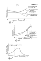
- This compressor displacement compensating feature permits controlling at the compressor suction while maintaining a nearly constant evaporator pressure (temperature) above freezing which has been found to result in substantially better high load performance and reduced power consumption at low ambients on a yearly basis, as shown by the graphs in Figures 5, 6 and 7.
- FIG. 5 there is shown a plot of evaporator and suction pressures versus ambient temperature with and without the discharge pressure compensation provided by the present invention.
- the suction pressure would remain relatively constant while the evaporator pressure would increase with ambient temperature, whereas with the discharge pressure compensation in conformity with the present invention both the evaporator pressure and suction pressure fall off substantially with increasing ambient temperature.
- This translates as shown in Figure 6 into a substantial horsepower reduction at lower ambients (i.e. below 80 o F; 27°C).
Abstract
Description
- This invention relates to a variable displacement compressor having suction and discharge cavities and a crankcase, whereby during operation variable suction and discharge pressures are produced in the respective cavities, and pressure is developed and controlled in the crankcase relative to the suction pressure to vary the compressor displacement by communication of the crankcase with the suction and discharge cavities, for example as disclosed in U.S. Patent No. 4,145,163 (Fogelberg et al). -
- In variable displacement refrigerant compressors wherein displacement or capacity control is provided by controlling the refrigerant gas pressure differential between the rearside of the pistons or crankcase and compressor suction, the practice has been to use a suction pressure-biased control valve arrangement to control this pressure differential. For example, U.S. Patent Nos. 3,861,829, 3,959,983 and 4,073,603 disclose compressor constructions which utilize piston blowby gas to the crankcase in a variable angle wobble plate type compressor and include a control valve which is biased by suction pressure to effect controlled communication between the crankcase and suction. In this type of compressor and control valve arrangement, the suction pressure (control signal) is employed to operate on a diaphragm or evacuated bellows, so that when the suction pressure increases, indicating a need for additional compressor displacement, the increased suction pressure causes the control valve to effect a decreased crankcase-suction pressure differential by bleeding the crankcase to suction, which has the effect of increasing the wobble plate angle and thus compressor displacement. Eventually, maximum displacement is obtained when there is zero crankcase-suction pressure differential. On the other hand, when the air conditioning capacity demand is lowered, the control valve is operated by the lowered suction pressure to close off the crankcase bleed to suction, so as to effect an increased crankcase-suction pressure differential, which has the effect of reducing the wobble plate angle and thereby decreasing the compressor displacement.
- A somewhat similar type of crankcase pressure control for achieving variable capacity is disclosed in the aforementioned U.S. Patent No. 4,145,163: this compressor construction uses a suction pressure-biased gas-filled bellows to operate a valve that selectively communicates compressor discharge and suction with the crankcase to control a slidable rather than variable- angle wobble plate to achieve variable capacity.
- In all the above arrangements, it is not possible solely by the use of such a suction pressure- responsive crankcase pressure control valve to control the compressor displacement so as to maintain a near- constant evaporator pressure (temperature) for achieving the desirable result of obtaining better high-load performance and reduced compressor power consumption at low ambients.
- For achieving such desirable result, a variable displacement compressor in accordance with the present invention is characterised in that displacement control valve means is responsive to both the suction pressure and discharge pressure and is operable to control the crankcase pressure relative to the suction pressure so as to increase the compressor displacement and thereby the discharge flow rate with increasing suction and discharge pressures.
- With this form of control of compressor displacement, also, the compressor control point for displacement change is depressed with increasing discharge pressure. In that the refrigerant flow rate and, in turn, suction line pressure drop increases with increasing discharge pressure, the control valve will depress the control point proportionally to the discharge pressure, and likewise the pressure drop. This added feature permits control to be effected at the compressor suction rather than by remote sensing at the evaporator, as well as maintaining a nearly constant evaporator pressure (temperature), which has been found to result in substantially better high load performance and reduced power consumption at low ambients.
- In the drawings:
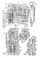
- Figure 1 is a sectional view, with parts in elevation of a preferred embodiment of a variable displacement refrigerant compressor in accordance with the present invention, of the variable angle wobble plate type, together with a schematic of an automotive air conditioning system in which the compressor is connected;
- Figure 2 is a fragmentary enlarged sectional view generally on the line 2-2 of Figure 1, in the direction of the arrows;
- Figure 3 is a fragmentary enlarged sectional view of a displacement control valve arrangement shown generally in Figure 1;
- Figure 4 is a fragmentary enlarged view showing portions of the displacement control valve arrangement of Figure 3; and
- Figures 5, 6 and 7 are graphs illustrating various operating characteristics produced by the compressor shown in Figure 1.
- In Figure 1 of the drawings, there is shown a -variable displacement refrigerant compressor 10 of the variable angle wobble plate type connected in an automotive air conditioning system-having the
normal condenser 12, orifice tube 14, evaporator 16 and accumulator 18 arranged in that order between the compressor's discharge and suction sides. The compressor 10 comprises acylinder block 20 having ahead 22 and a crankcase 24 sealingly clamped to opposite ends thereof. A drive shaft 26 is supported centrally in the compressor at thecylinder block 20 and crankcase 24 byradial needle bearings 28 and 30, respectively, and is axially retained by a thrust washer 32 inwardly of the needle bearing 28 and a thrust needle bearing 34 inwardly of the radial needle bearing 30. The drive shaft 26 extends through the crankcase 24 for connection to an automotive engine (not shown) by anelectromagnetic clutch 36 which is mounted on the crankcase and is driven from the engine by abelt 38 engaging apulley 40 on the clutch. - The
cylinder block 20 has fiveaxial cylinders 42 extending therethrough (only one being shown), which are equally angularly spaced about and equally radially spaced from the axis of the drive shaft 26. Thecylinders 42 extend parallel to the drive shaft 26, and a piston 44 havingseals 46 is mounted for reciprocal sliding movement in each of the cylinders. A separate piston rod 48 connects the rearside of each piston 44 to a non-rotary ring-shaped wobble plate 50 received about the drive shaft 26. Each of the piston rods 48 is connected to its respective piston 44 by a spherical rod end 52 which is retained in a socket 54 on the rearside of the piston by a retainer 56 that is swaged in place. The opposite end of each piston rod 48 is connected to thewobble plate 50 by a similar spherical rod end 58 which is retained in a socket 60 on the wobble plate by a split retainer ring 62 which is a snap fit with the wobble plate. - The
non-rotary wobble plate 50 is mounted at itsinner diameter 64 on a journal 66 of arotary drive plate 68, and is axially retained thereon against a thrust needle bearing.70 by a thrust washer 71 and snap ring 72. As is shown in Figure 2, thedrive plate 68 is pivotally connected at its journal 66 by a pair of pivot pins 74 to asleeve 76 which is slidably mounted on the drive shaft 26, the pins being mounted inaligned bores sleeve 76 respectively, with the common axis of the pivot pins intersecting at right angles to the axis of the drive shaft 16, to permit angulation of thedrive plate 68 andwobble plate 50 relative to the drive shaft. - The drive shaft 26 is drivingly connected to the
drive plate 68 by a lug 84 which extends freely through a longitudinal slot 86 in thesleeve 76. The drive lug 84 is threadably connected at one end to the drive shaft 26 at right angles thereto, and extends radially outwardly past the journal 66, where it is provided with aguideslot 88 for guiding the angulation of thedrive plate 68 andwobble plate 50. The drive lug 84 has flat-sided engagement on one side thereof at 90 with an ear 92 formed integrally with thedrive plate 68, and is retained thereagainst by a cross pin 94 which is at right angles to the drive shaft and is slidable in and guided by theguide slot 88 as thesleeve 76 moves along the drive shaft 26. The cross pin 94 is retained in place on thedrive plate 68 at its ear 92 by being provided with an enlarged head 96 at one end which engages the .lug at one side of theslot 88, and being received adjacent the other end in across-hole 98 in the drive plate ear 92, where it is retained by asnap ring 100. Thewobble plate 50, while being angulatable with therotary drive plate 68, is prevented from rotating therewith by aguide pin 102 on which aball guide 104 is slidably mounted and retained on the wobble plate. Theguide pin 102 is press-fitted at opposite ends in thecylinder block 20 and crankcase 24 parallel to the drive shaft 26, and theball guide 104 is retained between semi-cylindrical guide shoes 106 (only one being shown) which are slidably mounted for reciprocal radial movement in thewobble plate 50. - The drive lug arrangement for the
drive plate 68 and the anti-rotation guide arrangement for thewobble plate 50 are like those disclosed in greater detail in U.S. Patent Nos. 4,175,915 and 4,297,085 respectively assigned to the present applicants. With such arrangements, there is provided an essentially constant top-dead-center position for each of the pistons 44 by the pin follower 94, which is movable radially with respect to the drive lug 84 along its guide slot orcam track 88 as thesleeve 76 moves along the drive shaft 26 while the latter is driving thedrive plate 68 through the drive lug 84 and drive plate ear 92 in the direction indicated by the arrow in Figure 2. As a result, the angle of thewobble plate 50 is varied with respect to the axis of the drive shaft 26 between the solid-line large-angle position shown in Figure 1, which is full stroke, to the zero-angle phantom-line position shown, which is zero stroke, to thereby infinitessimally vary the stroke of the pistons and thus the displacement (capacity) of the compressor between these extremes. As is shown in Figure 1, there is provided a split ring return spring 107 which is mounted in a groove in.the drive shaft 26 and has one end that is engaged by thesleeve 76 during movement to the zero wobble-angle position and is thereby conditioned to initiate return movement. - The working ends of the
cylinders 42 are covered by avalve plate 108 which, together with an intake orsuction valve disk 110 and an exhaust. or discharge valve disk 112 located on opposite sides thereof, is clamped to thecylinder block 20 between the latter and thehead 22. Thehead 22 is provided with a suction cavity or chamber 114 which is connected through anexternal port 116 to receive gaseous refrigerant from the accumulator 18 downstream of the evaporator 16. The suction cavity 114 is open to an intake port 118 in thevalve plate 108 at the working end of each of thecylinders 42 where the refrigerant is admitted to the respective cylinders on their suction stroke each through areed valve 120 formed integrally with thesuction valve disk 110 at these locations. Then on the compression stroke, a discharge port 122 open to the working end of eachcylinder 42 allows the compressed refrigerant to be discharged into a discharge cavity orchamber -124 in thehead 22 by a discharge reed valve 126 which is formed integrally with the discharge valve disk 112 at these locations, the extent of opening of each of the discharge reed valves being limited by a rigid back-up strap 128 which is riveted at one end to thevalve plate 108. The compressor'sdischarge cavity 124 is connected to deliver the compressed gaseous refrigerant to thecondenser 12,from whence it is delivered through the orifice tube 14 back to the evaporator 16 to complete the refrigerant circuit shown in Figure 1. - It is known by those skilled in the art that given the above-described compressor arrangement, the wobble plate angle and thus compressor displacement can be controlled by controlling the refrigerant gas pressure in the sealed
interior 129 of the crankcase behind the pistons 44 relative to the suction pressure. In this type of control, the angle of the wobble plate is determined by a force balance , on the pistons wherein a slight elevation of the crankcase-suction pressure differential above a set suction pressure control point creates a net force on the pistons that results in a turning moment about the wobble plate pivot pins 74 that acts to reduce the wobble plate angle and thereby reduce the compressor capacity. Heretofore, it has been the practice to employ a control valve actuated by a bellows or diaphragm that is biased by compressor suction pressure and operates when the air conditioning capacity demand is high and the resulting suction pressure rises above the control point so as to maintain a bleed from crankcase to suction so that there is no crankcase-suction pressure differential. As a result, thewobble plate 50 will then angle to its full-stroke large-angle position shown in Figure 1, establishing maximum displacement. On the other hand, when the air conditioning capacity demand is lowered, and the suction pressure falls to the control point, a control valve with solely suction-pressure bias then operates to close off the crankcase connection with suction and either provide communication between the compressor discharge and the crankcase or allow the pressure therein to increase as a result of gas blow-by past the pistons. This has the effect of increasing the crankcase-suction pressure differential, which on slight elevation creates a net force on the pistons that results in a turning moment about the wobble plate pivot pins 74 that reduces the wobble plate angle and thereby reduces the compressor displacement. - In conformity with the present invention, there is provided an improved variable displacement control valve arrangement generally designated as 130 which is responsive to compressor discharge pressure as well as suction pressure to control the compressor displacement (capacity) so as to provide improved performance. As is shown in Figures 1 and 3, the
control valve arrangement 130 comprises avalve housing 132 which in the preferred embodiment is formed integrally in thehead 22 and has a steppedblind bore 133 having an openexternal end 134 through the periphery of thehead 22 and a closedinternal end 135 with stepped and progressively smaller bore portions designated 136, 138, 140 and 142. The innermost, largest-diameter bore portion 136 is open through a radial port 144 and apassage 146 in thehead 22 to the suction cavity 114, which is also in the compressor's head. The adjacent and smaller-diameter bore portion 138 is open to theinterior 129 of the crankcase through aradial port 148 in thehead 22, a port 150 in thevalve plate 108, passageways 152 and 154 in thecylinder block 20, a centralaxial passage 156 and intersecting radial passage 158 in the drive shaft 26, a centralaxial passage 160 in one of the drive plate pivot pins 74, and along the drive plate journal 66 past thewobble plate 50 and through its thrust needle bearing 70 (see Figures 2 and 3). The adjacent and smaller-diameter bore portion 140 is also open to theinterior 129 of the crankcase 24, but in a direct route through aradial port 162 inhead 22, aport 164 invalve plate 108 and a passage_166 in thecylinder block 20. The adjacent and smallest-diameter bore portion 142 at the closedend 136 of the stepped valve body bore is directly open to thedischarge cavity 124 through aradial port 168 in the head. - A cup-shaped valve bellows cover 170 having a closed outer end 172 and an open inner end 174 is sealingly inserted in a fixed position in the
open end 134 of the housing's steppedbore 133 at the large-diameter bore portion 136,with the positioning thereof determined by a cylindrical flange 176 on the cover engaging ashoulder 178 at the stepped outer end of the large-diameter bore portion 136,as best seen in Figure 3. Sealing thereof is provided by an O-ring 180 which is received in an internal groove in thelarge bore portion 136 and sealingly contacts with acylindrical land 182 of the bellows cover 170. Retention of the bellows cover 170 is provided by asnap ring 184 which is received in an interior groove in thebore end 134 and engages the outer side of the bellows cover flange 176. Thus the bellows cover 170 has its closed end 172 positioned in and closing theopen end 134 of thevalve housing 132 and its open end 174 facing inwardly towards the closed-end 135 of the valve housing. - An evacuated
bellows 186 is concentrically located within the bellows cover 170 and is seated against the latter's closed end 172. Thebellows 186 has a cup-shaped corrugated thin-wall metal casing 187 which at its closed and seated end receives a spring seat member 188. The other end of thebellows casing 187 is sealingly closed by anend member 190 through which anoutput rod 191 centrally extends, and is sealingly fixed thereto. The bellows 186 is evacuated so as to expand and contract in response to pressure changes within a surrounding annularpressure control cell 192 which is formed by the exterior of the bellows and the interior of the bellows cover 170 and is continuously open through aradial port 194 in the bellows cover 170 to the suction pressure-communicating port 144 of thecontrol valve housing 132. A compression coil spring 196 is located in the bellows and extends between the bellows' tworigid end members 188 and 190. The thus-captured spring 196 normally maintains the bellows in an extended position producing an outward force on theoutput rod 191. Theoutput rod 191 is tapered at its inner end 200 for guided movement in a blind bore 202 in the interior seat member 188 on contraction of the bellows. The exterior andopposite end 206 of theoutput rod 191 is pointed and seats in a coupling pocket 208 of an actuatingvalve pin member 210. The actuatingvalve pin member 210 is formed at its opposite end with a reduced valve-needle stem portion 212,and is.sealingly slidably supported for reciprocal movement along an intermediate constant-diameter portion or length 214 thereof in a central axial bore 216 formed in a stepped spool-shapedcylindrical valve body 218 mounted in the valve housing bore 133 inwardly of thebellows 186. - The
valve body 218 is formed with acylindrical land 219 which is press-fitted in the open end 174 of the bellows cover 170, this land extending sufficiently within the open end of the valve bellows cover to provide an axially'adjustable sealed juncture which is operable to provide calibration of the bellows unit. Moreover, a conicalcompression coil spring 220 is concentrically positioned intermediate thebellows end member 190 and the outer end of thevalve body 218,and acts to hold thebellows 186 in seating engagement with the bellows cover 170. With such arrangement, the pointedexterior end 206 of the bellows forcesoutput rod 191 to automatically align and couple with the valve pin pocket 208 in the actuatingvalve pin member 210,whereby the bellows output rod and the actuating valve pin member are constrained to move axially in unison. - The
central valve body 218 is sealingly received and positioned in the respective progressively smaller-diameter bore portions diameter land portions ring seal ring 226 at the large-diameter land portion 221 thus seals off the bellowspressure control cell 192, which is open to suction pressure and also co-operates with the O-ring seal 228 at the adjacent smaller-diametervalve body land 222 to seal off anannular chamber 232 at thebore portion 138 which is indirectly open through theport 148 to the crankcase. The O-ring seal 228 also co-operates with the O-ring seal 230 at the adjacent smaller-diametervalve body land 224 to seal off an annular chamber 234 extending about the spool valve body at thebore portion 140, which is directly open to the crankcase through theport 162. The valve body O-ring seal 230 also seals off theclosed end 136 of the valve body bore which is directly open at its smallest-diameter bore portion 142 through theport 168 to thedischarge cavity 124. - The central bore 216 through the mid-portion of the
valve body 218 joins at its end nearest the bellows with a counterbore 236,which in turn joins with alarger counterbore 238 that is open to the bellowspressure control cell 192 and thus to compressor suction. The counterbore 236 forms an annular crankcasebleed valve passage 240 which extends about the actuating valve pin member portion 214 and is connected by a pair of diametrically alignedradial ports 242 to thechamber 232 and thus to the crankcase. The larger-diameter counterbore 238 is open to the crankcasebleed valve passage 240 and slidably supports an enlarged cylindrical head portion 244 formed on the actuatingvalve pin member 210 at the bellows end thereof. The enlarged valve pin member head portion 244 operates to control crankcase bleed, and is provided for that purpose with atapered step 246 where it joins the long cylindrical pin portion 214. Thetapered step 246 provides a valve face which is engageable with aconical valve seat 248 forming the step between the valve body counterbores 236 and 238 to close the crankcasebleed valve passage 240, as shown in Figure 4 and described in more detail later. Alternatively, thevalve face 246 is movable off thevalve seat 248 to first open the crankcasebleed valve passage 240 to thecounterbore 238, and then upon slight further movement the valve head 244 uncovers anannular groove 249 in thecounterbore 238. Thegroove 249 is open to a pair of longitudinally extendingpassages 250 also in thecounterbore 238, which upon such valve movement are then effective to connect the crankcase bleed valve passage.240 to the bellows pressure control cell-192 and thus to the compressor suction cavity 114. - The central bore 216 in the
valve body 218 joins at its opposite end with a larger-diameter valve body bore 252 which is closed at one end by a tapered step 253 extending from the actuator valve pin member portion 214 and receives at its other end a crankcase chargevalve body member 254. The crankcase chargevalve body member 254 is press-fitted in the valve body bore 252 to form on one side thereof and within the valve body acavity 256 which extends about the actuator valve pin member portion 214 and is open through a radial port 258 in the valve body to the outwardly located chamber 234 and thus to the crankcase. The crankcase chargevalve body member 254 also co-operates with the small-diametervalve body portion 224 and its 0-ring seal 230 to form with theclosed end 135 of the valve housing bore achamber 260 which is open through theradial port 168 in the valve housing to thecompressor discharge cavity 124. - The crankcase charge
valve body member 254 is formed with a bell-shapedvalve cavity 262 which is exposed through anopen end 264 to the discharge pressure-connectedchamber 260 and is openable at the other end to a central crankcasecharge valve port 266 that receives the smaller-diameter stem portion 212 of the actuatingvalve pin member 210 and opens to thechamber 256 communicating with the crankcase. Mounted in the crankcase chargevalve body member 254 in thecavity 262 is crankcase charge valving comprising alarge ball segment 268 and asmall ball segment 270 which are welded together and are biased by a conicalcoil compression spring 272 so that thelarge ball segment 268 is held against the end of actuating valve pinmember stem portion 212 and normally seats on the complementary-shaped portion of the bell-shapedcavity 262 to close the crankcasecharge valve port 266. Thespring 272 is'seated at its opposite and enlarged end on·a spun-overannular edge 274 of thevalve body member 254 which defines theopening 264 to the valve cavity, there being mounted thereover ascreen 275 to filter out foreign matter. The conical spring's smaller end has a slightly smaller diameter than thesmaller ball segment 270, allowing this spring end to be snap-fastened for capture between the large and small ball segments. This facilitates the universal movement of the unitaryball valve element spring 272* so that the largeball valve element 268 will mate with its valve seat sufficiently to ensure their sealing relation when the valve is in its closed position shown in Figure 3,and so that theball valve element 268 will remain in alignment during valve opening movement to its full open position shown in Figure 4,in which condition the refrigerant gas at discharge pressure is allowed to flow through the crankcase charge valve port past the actuating valve pinmember stem portion 212 to the crankcase. - In addition to the spring biasing force acting to close the
valve element 268 on the crankcasecharge valve port 266 and also simultaneously open the crankcasebleed valve port 240 by acting through thevalve elements valve pin member 210 to effect the open position of its bleed valve end 244, there is effected a gas discharge pressure bias achieved by the discharge pressure incavity 260 acting on the unbalanced upstream side of the movable crankcasecharge valve segments charge valve port 266 by the controllingcharge valve elements - The large
ball valve segment 268 is caused to move off its valve seat and open the crankcasecharge valve port 266 against the force ofspring 272 and the variable discharge pressure bias by expansion of the suction pressure and spring-biasedbellows 186 acting through the actuatingvalve pin member 210, which at the same time acts at its valve head 244 to close the crankcasebleed valve port 240. On the other hand, these crankcase charge and crankcase bleed valve operations are reversed by contraction of the suction pressure-biasedbellows 186, assisted by the discharge pressure bias at thecrankcase charge valve 268. - Describing now the operation of the variable displacement compressor
control valve arrangement 130 in the system, gaseous refrigerant leaving the accumulator 18 at low pressure enters the compressor's suction cavity 114 and is discharged to the compressor'sdischarge cavity 124 and thence to thecondenser 12 at a certain rate dependent on the compressor's wobble plate angle. At the same time, the gaseous refrigerant at suction pressure is transmitted at the compressor to thebellows cell 192 to act on the evacuated bellows 186,which tends to expand in response to a decrease in the suction pressure thus acting thereon to provide a force on thebellows output rod 191 which urges movement of the actuatingvalve pin member 210 towards the position shown in Figure 4, closing the crankcasebleed valve port 240 and simultaneously opening the crankcasecharge valve port 266. On the other hand, the gaseous refrigerant discharge pressure at the compressor is at the same time transmitted to thevalve chamber 260 to act on theball valve arrangement charge valve port 266 and simultaneous opening of the crankcasebleed valve port 240 as shown in Figure 3. These variable pressure biases are in addition to the spring biases which act to normally condition thecontrol valve arrangement 130 so as to close the crankcasecharge valve port 266 and simultaneously open the crankcasebleed valve port 240, to thereby normally effect maximum compressor displacement by establishing zero crankcase-suction pressure differential. The objective is to match the compressor displacement with the air conditioning demand under all conditions so that the evaporator 16 is kept just above the freezing temperature (pressure) without cycling the compressor on and off with the clutch 36Jand with the optimum being to maintain as cold an evaporator as can be achieved at higher ambients without evaporator freeze, and at lower ambients as high an evaporator temperature as can be maintained while still supplying some de-humidification. To this end, the control point for thecontrol valve arrangement 130 determining displacement change is selected so that when the air conditioning capacity demand is high, the suction pressure at the compressor after the pressure drop from the evaporator 16 will be above the control point (e.g. 170-210 kPa). Thecontrol valve arrangement 130 is calibrated at assembly at thebellows 186 and with the spring biases so that the then existing discharge-suction pressure differential acting on the control valve arrangement is sufficiently high to maintain same in the condition shown in Figure 3, closing the crankcasecharge valve port 266 and opening the crankcasebleed valve port 240. Thecontrol valve arrangement 130 will then maintain a bleed from the crankcase to suction while simultaneously closing off discharge pressure thereto so that no crankcase-suction pressure differential is developed and as a result thewobble plate 50 will remain in its maximum angle position shown in solid line in Figure 1 to provide maximum compressor displacement. Then when the air conditioning capacity demand reduces and the suction pressure reaches the control point, the resulting change in the discharge-suction pressure differential acting on thecontrol valve arrangement 130 will condition its valving to then open the crankcasecharge valve port 266 and simultaneously close thecrankcase bleed port 240 and thereby elevate the crankcase-suction pressure differential. The angle of thewobble plate 50 is controlled'by a force balance on the pistons 44 so only a slight elevation (e.g. 40-100 kPal of the crankcase-suction pressure is effective to create a net force on the pistons that results in a moment about the wobble plate pivot axis that reduces the wobble plate angle and thereby the compressor displacement. Moreover, in that the control valve bellows 186 in addition to being acted on by the suction control pressure has to also overcome discharge pressure in expanding to elevate the crankcase-suction pressure differential to reduce compressor displacement, the displacement change control point is thus depressed with increasing discharge pressure (higher ambients). In that the refrigerant flow rate, and in turn suction line pressure drop, increases with increasing discharge pressure (higher ambients) the control valve will depress the control point proportionally to the discharge pressure and likewise suction line pressure drop. This compressor displacement compensating feature permits controlling at the compressor suction while maintaining a nearly constant evaporator pressure (temperature) above freezing which has been found to result in substantially better high load performance and reduced power consumption at low ambients on a yearly basis, as shown by the graphs in Figures 5, 6 and 7. - Referring first to Figure 5, there is shown a plot of evaporator and suction pressures versus ambient temperature with and without the discharge pressure compensation provided by the present invention. As can be seen in this Figure, without the discharge pressure compensation the suction pressure would remain relatively constant while the evaporator pressure would increase with ambient temperature, whereas with the discharge pressure compensation in conformity with the present invention both the evaporator pressure and suction pressure fall off substantially with increasing ambient temperature. This translates as shown in Figure 6 into a substantial horsepower reduction at lower ambients (i.e. below 80oF; 27°C). There is some increase in horsepower at higher ambients, but the reduction in evaporator pressure (temperature) was found to offset the slight horsepower penalty, as can be seen in Figure 7, since operation under these conditions occurs for only a small percentage of the total on-time of the compressor during a typical year. Weighted on a time basis, the compressor horsepower is substantially lower when using the discharge pressure compensation thus provided than would be the case without discharge pressure compensation, due to the power reduction realized at the lower ambients occurring more of the time in a typical year.
Claims (6)
Applications Claiming Priority (2)
| Application Number | Priority Date | Filing Date | Title |
|---|---|---|---|
| US06/352,225 US4428718A (en) | 1982-02-25 | 1982-02-25 | Variable displacement compressor control valve arrangement |
| US352225 | 1999-07-13 |
Publications (2)
| Publication Number | Publication Date |
|---|---|
| EP0089112A1 true EP0089112A1 (en) | 1983-09-21 |
| EP0089112B1 EP0089112B1 (en) | 1986-07-09 |
Family
ID=23384279
Family Applications (1)
| Application Number | Title | Priority Date | Filing Date |
|---|---|---|---|
| EP83300635A Expired EP0089112B1 (en) | 1982-02-25 | 1983-02-09 | Variable displacement compressor |
Country Status (6)
| Country | Link |
|---|---|
| US (1) | US4428718A (en) |
| EP (1) | EP0089112B1 (en) |
| JP (1) | JPS58158382A (en) |
| CA (1) | CA1206129A (en) |
| DE (1) | DE3364399D1 (en) |
| MX (1) | MX7409E (en) |
Cited By (5)
| Publication number | Priority date | Publication date | Assignee | Title |
|---|---|---|---|---|
| GB2153922A (en) * | 1984-02-02 | 1985-08-29 | Sanden Corp | Compressor capacity control |
| DE3729579A1 (en) * | 1986-09-05 | 1988-03-10 | Toyoda Automatic Loom Works | SWASH DISC COMPRESSOR WITH VARIABLE CONVEYING PERFORMANCE |
| EP0259760A2 (en) * | 1986-09-02 | 1988-03-16 | Nippondenso Co., Ltd. | Variable displacement swash-plate type compressor |
| EP0491526A1 (en) * | 1990-12-15 | 1992-06-24 | Sanden Corporation | Slant plate type compressor with variable displacement mechanism |
| EP0536989A1 (en) * | 1991-10-07 | 1993-04-14 | Sanden Corporation | Slant plate type compressor with variable capacity control mechanism |
Families Citing this family (121)
| Publication number | Priority date | Publication date | Assignee | Title |
|---|---|---|---|---|
| US4526516A (en) * | 1983-02-17 | 1985-07-02 | Diesel Kiki Co., Ltd. | Variable capacity wobble plate compressor capable of controlling angularity of wobble plate with high responsiveness |
| JPS60135680A (en) * | 1983-12-23 | 1985-07-19 | Sanden Corp | Oscillation type compressor |
| JPS60175782A (en) * | 1984-02-21 | 1985-09-09 | Sanden Corp | Variable capacity rolling compressor |
| DE3416637A1 (en) * | 1984-05-05 | 1985-11-14 | Diesel Kiki Co. Ltd., Tokio/Tokyo | Swash plate compressor |
| US4553905A (en) * | 1984-05-09 | 1985-11-19 | Diesel Kiki Co., Ltd. | Variable capacity wobble plate compressor with high stability of capacity control |
| US4674957A (en) * | 1984-12-22 | 1987-06-23 | Kabushiki Kaisha Toyoda Jidoshokki Seisakusho | Control mechanism for variable displacement swash plate type compressor |
| JPH0637874B2 (en) * | 1984-12-28 | 1994-05-18 | 株式会社豊田自動織機製作所 | Variable capacity compressor |
| JPS61134580U (en) * | 1985-02-09 | 1986-08-22 | ||
| US4685866A (en) * | 1985-03-20 | 1987-08-11 | Kabushiki Kaisha Toyoda Jidoshokki Seisakusho | Variable displacement wobble plate type compressor with wobble angle control unit |
| US4688997A (en) * | 1985-03-20 | 1987-08-25 | Kabushiki Kaisha Toyoda Jidoshokki Seisakusho | Variable displacement compressor with variable angle wobble plate and wobble angle control unit |
| US4712982A (en) * | 1985-03-25 | 1987-12-15 | Kabushiki Kaisha Toyoda Jidoshokki Seisakusho | Variable displacement wobble plate type compressor with guide means for wobble plate |
| JPS61291783A (en) * | 1985-06-19 | 1986-12-22 | Toyoda Autom Loom Works Ltd | Guide device for swingable swash plate in variable capacity compressor |
| US4621983A (en) * | 1985-04-12 | 1986-11-11 | Diesel Kiki Co., Ltd. | Variable capacity wobble plate compressor with improved means for returning lubricating oil to crankcase |
| JPS61261681A (en) * | 1985-05-16 | 1986-11-19 | Toyoda Autom Loom Works Ltd | Variable mechanism for compression displacement in swash plate type compressor |
| JPS62674A (en) * | 1985-06-27 | 1987-01-06 | Toyoda Autom Loom Works Ltd | Capacity controller for variable angle swing swash type variable capacity compressor |
| JPS6282283A (en) * | 1985-10-02 | 1987-04-15 | Toyoda Autom Loom Works Ltd | Swaying swash plate type compressor |
| JPS6287679A (en) * | 1985-10-11 | 1987-04-22 | Sanden Corp | Variable displacement compressor |
| JPH0335899Y2 (en) * | 1985-10-21 | 1991-07-30 | ||
| JPS62129593A (en) * | 1985-11-28 | 1987-06-11 | Diesel Kiki Co Ltd | Vane type compressor |
| JPS62203980A (en) * | 1986-03-03 | 1987-09-08 | Toyoda Autom Loom Works Ltd | Mechanism for controlling wobbling angle of wobble plate in wobble plate type compressor |
| JPS62206277A (en) * | 1986-03-06 | 1987-09-10 | Toyoda Autom Loom Works Ltd | Mechanism for returning swing slant angle of wobble plate in swing swash plate type compressor |
| JPS62218668A (en) * | 1986-03-18 | 1987-09-26 | Toyoda Autom Loom Works Ltd | Control mechanism for pressure of crankcase in oscillating swash plate type compressor |
| JPH0756259B2 (en) * | 1986-03-25 | 1995-06-14 | 株式会社豊田自動織機製作所 | Variable capacity mechanism of compressor |
| JPH0765567B2 (en) * | 1986-04-09 | 1995-07-19 | 株式会社豊田自動織機製作所 | Control Mechanism of Crank Chamber Pressure in Oscillating Swash Plate Compressor |
| JPS62253970A (en) * | 1986-04-25 | 1987-11-05 | Toyota Autom Loom Works Ltd | Variable capacity compressor |
| US4732544A (en) * | 1986-06-12 | 1988-03-22 | Diesel Kiki Co., Ltd. | Variable capacity wobble plate compressor |
| US4683765A (en) * | 1986-07-07 | 1987-08-04 | General Motors Corporation | Variable displacement wobble plate compressor guide rod mounting arrangement |
| JPS6316177A (en) * | 1986-07-08 | 1988-01-23 | Sanden Corp | Variable displacement type compressor |
| JPS6329067A (en) * | 1986-07-21 | 1988-02-06 | Sanden Corp | Oscillating type continuously variable displacement compressor |
| JPH0217186Y2 (en) * | 1986-07-23 | 1990-05-14 | ||
| US4745814A (en) * | 1986-07-24 | 1988-05-24 | General Motors Corporation | Variable displacement wobble plate compressor slide and guide joint |
| JPH037584Y2 (en) * | 1986-08-01 | 1991-02-25 | ||
| JPH0610468B2 (en) * | 1986-08-07 | 1994-02-09 | サンデン株式会社 | Variable capacity compressor |
| JPS6341677A (en) * | 1986-08-08 | 1988-02-22 | Sanden Corp | Variable capacity compressor |
| JPS6365177A (en) * | 1986-09-05 | 1988-03-23 | Hitachi Ltd | Variable displacement swash plate type compressor |
| JPS6375371A (en) * | 1986-09-16 | 1988-04-05 | Sanden Corp | Variable displacement compressor |
| JPS6351172U (en) * | 1986-09-19 | 1988-04-06 | ||
| JPH0447430Y2 (en) * | 1986-09-19 | 1992-11-09 | ||
| KR880005363A (en) * | 1986-10-01 | 1988-06-28 | 미타 가츠시게 | Variable displacement compressor |
| JPH0784865B2 (en) * | 1986-12-16 | 1995-09-13 | カルソニック株式会社 | Controller for variable capacity swash plate type compressor |
| JPH0819904B2 (en) * | 1987-01-27 | 1996-03-04 | カルソニック株式会社 | Variable capacity swash plate type compressor |
| KR960009857B1 (en) * | 1987-02-19 | 1996-07-24 | 산덴 가부시끼가이샤 | Wobble plate type compressor with variable displacement mechanism |
| JPS63205473A (en) * | 1987-02-19 | 1988-08-24 | Sanden Corp | Swash plate type variable displacement compressor |
| JPS63205469A (en) * | 1987-02-20 | 1988-08-24 | Sanden Corp | Variable displacement swash plate type compressor |
| JPS63149319U (en) * | 1987-03-24 | 1988-09-30 | ||
| JPS63243469A (en) * | 1987-03-28 | 1988-10-11 | Toyota Autom Loom Works Ltd | Pressure control mechanism of crank case for swash plate type compressor |
| JPH0223829Y2 (en) * | 1987-05-19 | 1990-06-28 | ||
| AU615200B2 (en) * | 1987-06-30 | 1991-09-26 | Sanden Corporation | Refrigerant circuit with passageway control mechanism |
| JP2714398B2 (en) * | 1987-06-30 | 1998-02-16 | サンデン株式会社 | Refrigeration circuit with refrigerant flow control mechanism |
| JPH0717151B2 (en) * | 1987-07-04 | 1995-03-01 | 株式会社豊田自動織機製作所 | Variable capacity compressor operation control method |
| JP2511056B2 (en) * | 1987-07-23 | 1996-06-26 | サンデン株式会社 | Variable capacity swash plate compressor |
| JPS6429679A (en) * | 1987-07-24 | 1989-01-31 | Sanden Corp | Capacity variable swash plate type compressor |
| JPS6427486U (en) * | 1987-08-10 | 1989-02-16 | ||
| JPS6427487U (en) * | 1987-08-10 | 1989-02-16 | ||
| US5168716A (en) * | 1987-09-22 | 1992-12-08 | Sanden Corporation | Refrigeration system having a compressor with an internally and externally controlled variable displacement mechanism |
| US5189886A (en) * | 1987-09-22 | 1993-03-02 | Sanden Corporation | Refrigerating system having a compressor with an internally and externally controlled variable displacement mechanism |
| US5027612A (en) * | 1987-09-22 | 1991-07-02 | Sanden Corporation | Refrigerating system having a compressor with an internally and externally controlled variable displacement mechanism |
| JPS6480776A (en) * | 1987-09-22 | 1989-03-27 | Sanden Corp | Volume-variable compressor |
| JPH01141119A (en) * | 1987-11-25 | 1989-06-02 | Diesel Kiki Co Ltd | Air conditioner |
| JPH01142276A (en) * | 1987-11-27 | 1989-06-05 | Sanden Corp | Variable displacement swash-plate type compressor |
| JPH01142277A (en) * | 1987-11-30 | 1989-06-05 | Sanden Corp | Variable displacement compressor |
| US5174727A (en) * | 1987-11-30 | 1992-12-29 | Sanden Corporation | Slant plate type compressor with variable displacement mechanism |
| JPH01182581A (en) * | 1988-01-14 | 1989-07-20 | Honda Motor Co Ltd | Control device for variable displacement compressor |
| US4836090A (en) * | 1988-01-27 | 1989-06-06 | General Motors Corporation | Balanced variable stroke axial piston machine |
| JPH01230966A (en) * | 1988-03-10 | 1989-09-14 | Fuji Koki Seisakusho:Kk | Control of refrigerating system and thermostatic expansion valve |
| JPH0413425Y2 (en) * | 1988-04-28 | 1992-03-27 | ||
| JPH0697034B2 (en) * | 1988-06-07 | 1994-11-30 | 松下電器産業株式会社 | Movable swash plate compressor |
| JP2661166B2 (en) * | 1988-08-05 | 1997-10-08 | 日産自動車株式会社 | Vehicle air conditioner |
| JP2600317B2 (en) * | 1988-08-11 | 1997-04-16 | 株式会社豊田自動織機製作所 | Variable capacity compressor |
| US5051070A (en) * | 1988-12-29 | 1991-09-24 | Aisin Seiki Kabushiki Kaisha | Variable capacity compressor |
| JPH085310B2 (en) * | 1989-04-29 | 1996-01-24 | 日産自動車株式会社 | Vehicle air conditioner |
| JPH0788138B2 (en) * | 1989-04-29 | 1995-09-27 | 日産自動車株式会社 | Vehicle air conditioner |
| JPH0331581A (en) * | 1989-06-28 | 1991-02-12 | Sanden Corp | Variable-capacity swash plate type compressor |
| JPH0343685A (en) * | 1989-07-05 | 1991-02-25 | Sanden Corp | Capacity variable type oscillating compressor |
| JPH0370877A (en) * | 1989-08-10 | 1991-03-26 | Sanden Corp | Cam plate type compressor |
| JP2892718B2 (en) * | 1989-11-17 | 1999-05-17 | 株式会社日立製作所 | Variable displacement compressor |
| JP2943934B2 (en) * | 1990-03-20 | 1999-08-30 | サンデン株式会社 | Variable capacity swash plate compressor |
| JP2846089B2 (en) * | 1990-09-14 | 1999-01-13 | 株式会社日立製作所 | Variable displacement compressor |
| US5094590A (en) * | 1990-10-09 | 1992-03-10 | General Motors Corporation | Variable displacement compressor with shaft end play compensation |
| US5127314A (en) * | 1990-11-30 | 1992-07-07 | General Motors Corporation | Compensating cam socket plate torque restraint assembly for a variable displacement compressor |
| US5079996A (en) * | 1991-01-08 | 1992-01-14 | General Motors Corporation | Positive displacement control for a variable displacement compressor |
| US5152673A (en) * | 1991-08-09 | 1992-10-06 | General Motors Corporation | Fluid pumping assembly having a control valve boss fluid by-pass |
| US5167492A (en) * | 1991-08-19 | 1992-12-01 | General Motors Corporation | Fluid pumping assembly having a lubrication circuit functioning independent of the orientation of the fluid pumping assembly |
| JPH0599136A (en) * | 1991-10-23 | 1993-04-20 | Sanden Corp | Variable capacity type swash plate type compressor |
| US5172753A (en) * | 1991-10-15 | 1992-12-22 | General Motors Corporation | Automobile heating system |
| US5368449A (en) * | 1991-12-24 | 1994-11-29 | Kabushiki Kaisha Toyoda Jidoshokki Seisakusho | Refrigerant gas guiding mechanism for piston type compressor |
| US5201233A (en) * | 1992-01-29 | 1993-04-13 | General Motors Corporation | Retainer assembly with dished retaining ring |
| JP3114398B2 (en) * | 1992-11-12 | 2000-12-04 | 株式会社豊田自動織機製作所 | Oscillating swash plate type variable displacement compressor |
| JP3178630B2 (en) * | 1992-12-21 | 2001-06-25 | 株式会社豊田自動織機製作所 | Variable displacement compressor |
| US5486098A (en) * | 1992-12-28 | 1996-01-23 | Kabushiki Kaisha Toyoda Jidoshokki Seisakusho | Swash plate type variable displacement compressor |
| JP3178631B2 (en) * | 1993-01-11 | 2001-06-25 | 株式会社豊田自動織機製作所 | Control valve for variable displacement compressor |
| US5360319A (en) * | 1993-05-17 | 1994-11-01 | General Motors Corporation | Compressor assembly having control valve for triggered pressure actuated clutch |
| US5364237A (en) * | 1993-05-20 | 1994-11-15 | General Motors Corporation | Compressor assembly having a clutch triggered by a small compressor and actuated by discharge pressure |
| US5273409A (en) * | 1993-05-20 | 1993-12-28 | General Motors Corporation | Compressor assembly including an electromagnetically triggered pressure actuated internal clutch |
| JPH07174071A (en) * | 1993-08-10 | 1995-07-11 | Sanden Corp | Discharge mechanism for compressor |
| JP3355002B2 (en) * | 1993-10-15 | 2002-12-09 | 株式会社豊田自動織機 | Control valve for variable displacement compressor |
| JPH0815188A (en) * | 1995-07-14 | 1996-01-19 | Hitachi Ltd | Surface analyzer |
| US5868556A (en) * | 1995-11-24 | 1999-02-09 | Calsonic Corporation | Swash-plate type compressor |
| JPH1162823A (en) * | 1997-08-08 | 1999-03-05 | Sanden Corp | Variable displacement compressor |
| JP3591234B2 (en) * | 1997-08-27 | 2004-11-17 | 株式会社豊田自動織機 | Control valve for variable displacement compressor |
| JP4000694B2 (en) * | 1997-12-26 | 2007-10-31 | 株式会社豊田自動織機 | Capacity control valve in variable capacity compressor |
| JPH11343974A (en) * | 1998-05-29 | 1999-12-14 | Toyota Autom Loom Works Ltd | Reciprocating compressor |
| JP3435077B2 (en) | 1998-09-16 | 2003-08-11 | 株式会社鷺宮製作所 | Bellows pressure operated valve |
| JP2000145629A (en) * | 1998-11-11 | 2000-05-26 | Tgk Co Ltd | Variable displacement compressor |
| JP2000265960A (en) | 1999-03-15 | 2000-09-26 | Toyota Autom Loom Works Ltd | Fluid machine |
| JP2000291541A (en) * | 1999-04-06 | 2000-10-17 | Toyota Autom Loom Works Ltd | Layout method for variable displacement compressor and manufacture thereof |
| JP2000303951A (en) * | 1999-04-20 | 2000-10-31 | Toyota Autom Loom Works Ltd | Piston type compressor |
| US6367283B1 (en) | 2000-04-14 | 2002-04-09 | Ranco Incorporated | Three-stage electronically variable orifice tube |
| US6340293B1 (en) | 2000-08-25 | 2002-01-22 | Delphi Technologies Inc | Clutchless compressor control valve with integral by pass feature |
| US6786703B2 (en) | 2001-11-02 | 2004-09-07 | Delphi Technologies, Inc. | Variable capacity air conditioning compressor with improved crankcase oil retention |
| JP4078229B2 (en) | 2002-03-20 | 2008-04-23 | カルソニックカンセイ株式会社 | Compressor |
| EP1589223B1 (en) * | 2003-01-22 | 2019-04-24 | Valeo Japan Co., Ltd. | Control valve of variable displacement compressor |
| JP2007512489A (en) | 2003-11-24 | 2007-05-17 | アルーマナ、マイクロウ、エルエルシー | Microvalve device suitable for control of variable displacement compressor |
| US20050180860A1 (en) * | 2004-02-17 | 2005-08-18 | Dewispelaere Bradley J. | Compressor having swash plate assembly |
| JP2008522064A (en) * | 2004-11-25 | 2008-06-26 | イグゼティック エムアーツェー ゲゼルシャフト ミット ベシュレンクテル ハフツング | Axial flow piston machine |
| JP2006266172A (en) * | 2005-03-24 | 2006-10-05 | Denso Corp | Compressor displacement control device and refrigeration cycle device |
| JP2007077863A (en) * | 2005-09-14 | 2007-03-29 | Toyota Industries Corp | Control valve for clutch type variable displacement compressor |
| JP5075425B2 (en) | 2007-02-19 | 2012-11-21 | サンデン株式会社 | Volume control valve for variable capacity compressor |
| US20080289347A1 (en) * | 2007-05-22 | 2008-11-27 | Kadle Prasad S | Control method for a variable displacement refrigerant compressor in a high-efficiency AC system |
| JP6091503B2 (en) | 2012-05-24 | 2017-03-08 | イーグル工業株式会社 | Capacity control valve |
| CN102937075A (en) * | 2012-11-07 | 2013-02-20 | 苏州新豪轴承有限公司 | Vehicle air conditioner compression device |
Citations (6)
| Publication number | Priority date | Publication date | Assignee | Title |
|---|---|---|---|---|
| US3861829A (en) * | 1973-04-04 | 1975-01-21 | Borg Warner | Variable capacity wobble plate compressor |
| US3959983A (en) * | 1973-04-04 | 1976-06-01 | Borg-Warner Corporation | Variable capacity wobble plate compressor |
| US4037993A (en) * | 1976-04-23 | 1977-07-26 | Borg-Warner Corporation | Control system for variable displacement compressor |
| US4073603A (en) * | 1976-02-06 | 1978-02-14 | Borg-Warner Corporation | Variable displacement compressor |
| US4108577A (en) * | 1977-06-09 | 1978-08-22 | General Motors Corporation | Variable displacement compressor |
| US4145163A (en) * | 1977-09-12 | 1979-03-20 | Borg-Warner Corporation | Variable capacity wobble plate compressor |
Family Cites Families (1)
| Publication number | Priority date | Publication date | Assignee | Title |
|---|---|---|---|---|
| US4231713A (en) * | 1979-04-09 | 1980-11-04 | General Motors Corporation | Compressor modulation delay valve for variable capacity compressor |
-
1982
- 1982-02-25 US US06/352,225 patent/US4428718A/en not_active Expired - Lifetime
- 1982-11-25 CA CA000416370A patent/CA1206129A/en not_active Expired
-
1983
- 1983-02-09 DE DE8383300635T patent/DE3364399D1/en not_active Expired
- 1983-02-09 EP EP83300635A patent/EP0089112B1/en not_active Expired
- 1983-02-21 MX MX8310493U patent/MX7409E/en unknown
- 1983-02-25 JP JP58030685A patent/JPS58158382A/en active Granted
Patent Citations (6)
| Publication number | Priority date | Publication date | Assignee | Title |
|---|---|---|---|---|
| US3861829A (en) * | 1973-04-04 | 1975-01-21 | Borg Warner | Variable capacity wobble plate compressor |
| US3959983A (en) * | 1973-04-04 | 1976-06-01 | Borg-Warner Corporation | Variable capacity wobble plate compressor |
| US4073603A (en) * | 1976-02-06 | 1978-02-14 | Borg-Warner Corporation | Variable displacement compressor |
| US4037993A (en) * | 1976-04-23 | 1977-07-26 | Borg-Warner Corporation | Control system for variable displacement compressor |
| US4108577A (en) * | 1977-06-09 | 1978-08-22 | General Motors Corporation | Variable displacement compressor |
| US4145163A (en) * | 1977-09-12 | 1979-03-20 | Borg-Warner Corporation | Variable capacity wobble plate compressor |
Cited By (8)
| Publication number | Priority date | Publication date | Assignee | Title |
|---|---|---|---|---|
| GB2153922A (en) * | 1984-02-02 | 1985-08-29 | Sanden Corp | Compressor capacity control |
| EP0259760A2 (en) * | 1986-09-02 | 1988-03-16 | Nippondenso Co., Ltd. | Variable displacement swash-plate type compressor |
| EP0259760A3 (en) * | 1986-09-02 | 1990-05-16 | Nippondenso Co., Ltd. | Variable displacement swash-plate type compressor |
| EP0519522A2 (en) * | 1986-09-02 | 1992-12-23 | Nippondenso Co., Ltd. | Variable displacement swash-plate type compressor |
| EP0519522A3 (en) * | 1986-09-02 | 1993-09-01 | Nippondenso Co., Ltd. | Variable displacement swash-plate type compressor |
| DE3729579A1 (en) * | 1986-09-05 | 1988-03-10 | Toyoda Automatic Loom Works | SWASH DISC COMPRESSOR WITH VARIABLE CONVEYING PERFORMANCE |
| EP0491526A1 (en) * | 1990-12-15 | 1992-06-24 | Sanden Corporation | Slant plate type compressor with variable displacement mechanism |
| EP0536989A1 (en) * | 1991-10-07 | 1993-04-14 | Sanden Corporation | Slant plate type compressor with variable capacity control mechanism |
Also Published As
| Publication number | Publication date |
|---|---|
| DE3364399D1 (en) | 1986-08-14 |
| EP0089112B1 (en) | 1986-07-09 |
| JPS58158382A (en) | 1983-09-20 |
| CA1206129A (en) | 1986-06-17 |
| US4428718A (en) | 1984-01-31 |
| MX7409E (en) | 1988-10-06 |
| JPS6240555B2 (en) | 1987-08-28 |
Similar Documents
| Publication | Publication Date | Title |
|---|---|---|
| EP0089112B1 (en) | Variable displacement compressor | |
| US4480964A (en) | Refrigerant compressor lubrication system | |
| CA1132508A (en) | Compressor modulation delay valve for variable capacity compressor | |
| AU659217B2 (en) | Slant plate type compressor with variable capacity control mechanism | |
| US4730986A (en) | Variable displacement wobble plate type compressor with wobble angle control valve | |
| US4580950A (en) | Sliding-vane rotary compressor for automotive air conditioner | |
| US5165863A (en) | Slant plate type compressor with variable capacity control mechanism | |
| USRE35672E (en) | Slant plate type compressor with variable capacity control mechanism | |
| US5094589A (en) | Slant plate type compressor with variable displacement mechanism | |
| EP0550201B1 (en) | Slant plate type compressor with variable capacity control mechanism | |
| US20030019226A1 (en) | Variable displacement compressor and displacement control valve for variable displacement compressor | |
| US4960367A (en) | Slant plate type compressor with variable displacement mechanism | |
| US5620310A (en) | Control valve for a variable displacement refrigerant compressor | |
| US6302656B1 (en) | Solenoid controlled valve and variable displacement compressor | |
| US6662582B2 (en) | Displacement control valve | |
| US5145325A (en) | Slant plate type compressor with variable displacement mechanism | |
| US4752189A (en) | Valve arrangement for a variable displacement compressor | |
| CA2020568C (en) | Slant plate type compressor with variable displacement mechanism | |
| AU646336B2 (en) | Slant plate type compressor with variable displacement mechanism | |
| US4236875A (en) | Pressure operated hydraulic control valve | |
| US4709555A (en) | Variable delivery refrigerant compressor of double-acting swash plate type | |
| EP0090486B1 (en) | Refrigerant compressor with lubrication system | |
| US5039282A (en) | Slant plate type compressor with variable displacement mechanism | |
| CA1123402A (en) | Pressure operated hydraulic control valve | |
| JPH04321779A (en) | Swash plate type variable capacity compressor |
Legal Events
| Date | Code | Title | Description |
|---|---|---|---|
| PUAI | Public reference made under article 153(3) epc to a published international application that has entered the european phase |
Free format text: ORIGINAL CODE: 0009012 |
|
| AK | Designated contracting states |
Designated state(s): DE FR IT |
|
| 17P | Request for examination filed |
Effective date: 19830928 |
|
| ITF | It: translation for a ep patent filed |
Owner name: BARZANO' E ZANARDO ROMA S.P.A. |
|
| GRAA | (expected) grant |
Free format text: ORIGINAL CODE: 0009210 |
|
| AK | Designated contracting states |
Kind code of ref document: B1 Designated state(s): DE FR IT |
|
| ET | Fr: translation filed | ||
| REF | Corresponds to: |
Ref document number: 3364399 Country of ref document: DE Date of ref document: 19860814 |
|
| PLBE | No opposition filed within time limit |
Free format text: ORIGINAL CODE: 0009261 |
|
| STAA | Information on the status of an ep patent application or granted ep patent |
Free format text: STATUS: NO OPPOSITION FILED WITHIN TIME LIMIT |
|
| 26N | No opposition filed | ||
| ITTA | It: last paid annual fee | ||
| PGFP | Annual fee paid to national office [announced via postgrant information from national office to epo] |
Ref country code: FR Payment date: 20020215 Year of fee payment: 20 |
|
| PGFP | Annual fee paid to national office [announced via postgrant information from national office to epo] |
Ref country code: DE Payment date: 20020318 Year of fee payment: 20 |