EP0087802A2 - Fuel control apparatus for internal combustion engine - Google Patents
Fuel control apparatus for internal combustion engine Download PDFInfo
- Publication number
- EP0087802A2 EP0087802A2 EP83101981A EP83101981A EP0087802A2 EP 0087802 A2 EP0087802 A2 EP 0087802A2 EP 83101981 A EP83101981 A EP 83101981A EP 83101981 A EP83101981 A EP 83101981A EP 0087802 A2 EP0087802 A2 EP 0087802A2
- Authority
- EP
- European Patent Office
- Prior art keywords
- fuel
- engine
- time
- control apparatus
- air
- Prior art date
- Legal status (The legal status is an assumption and is not a legal conclusion. Google has not performed a legal analysis and makes no representation as to the accuracy of the status listed.)
- Granted
Links
Images


Classifications
-
- F—MECHANICAL ENGINEERING; LIGHTING; HEATING; WEAPONS; BLASTING
- F02—COMBUSTION ENGINES; HOT-GAS OR COMBUSTION-PRODUCT ENGINE PLANTS
- F02D—CONTROLLING COMBUSTION ENGINES
- F02D41/00—Electrical control of supply of combustible mixture or its constituents
- F02D41/02—Circuit arrangements for generating control signals
- F02D41/14—Introducing closed-loop corrections
- F02D41/1438—Introducing closed-loop corrections using means for determining characteristics of the combustion gases; Sensors therefor
- F02D41/1477—Introducing closed-loop corrections using means for determining characteristics of the combustion gases; Sensors therefor characterised by the regulation circuit or part of it,(e.g. comparator, PI regulator, output)
- F02D41/1481—Using a delaying circuit
-
- F—MECHANICAL ENGINEERING; LIGHTING; HEATING; WEAPONS; BLASTING
- F02—COMBUSTION ENGINES; HOT-GAS OR COMBUSTION-PRODUCT ENGINE PLANTS
- F02D—CONTROLLING COMBUSTION ENGINES
- F02D41/00—Electrical control of supply of combustible mixture or its constituents
- F02D41/02—Circuit arrangements for generating control signals
- F02D41/18—Circuit arrangements for generating control signals by measuring intake air flow
- F02D41/187—Circuit arrangements for generating control signals by measuring intake air flow using a hot wire flow sensor
-
- F—MECHANICAL ENGINEERING; LIGHTING; HEATING; WEAPONS; BLASTING
- F02—COMBUSTION ENGINES; HOT-GAS OR COMBUSTION-PRODUCT ENGINE PLANTS
- F02D—CONTROLLING COMBUSTION ENGINES
- F02D41/00—Electrical control of supply of combustible mixture or its constituents
- F02D41/30—Controlling fuel injection
- F02D41/32—Controlling fuel injection of the low pressure type
- F02D41/34—Controlling fuel injection of the low pressure type with means for controlling injection timing or duration
- F02D41/345—Controlling injection timing
-
- Y—GENERAL TAGGING OF NEW TECHNOLOGICAL DEVELOPMENTS; GENERAL TAGGING OF CROSS-SECTIONAL TECHNOLOGIES SPANNING OVER SEVERAL SECTIONS OF THE IPC; TECHNICAL SUBJECTS COVERED BY FORMER USPC CROSS-REFERENCE ART COLLECTIONS [XRACs] AND DIGESTS
- Y02—TECHNOLOGIES OR APPLICATIONS FOR MITIGATION OR ADAPTATION AGAINST CLIMATE CHANGE
- Y02T—CLIMATE CHANGE MITIGATION TECHNOLOGIES RELATED TO TRANSPORTATION
- Y02T10/00—Road transport of goods or passengers
- Y02T10/10—Internal combustion engine [ICE] based vehicles
- Y02T10/40—Engine management systems
Definitions
- This invention relates to fuel control apparatus for internal combustion engine, and particularly to a fuel injection control apparatus for internal combustion engine capable of correcting for the response lag in fuel suction path.
- a conventional fuel control apparatus for internal combustion engine has a sensor responsive to a particular exhaust gas concentration in the exhaust pipe to produce a signal, which is fed back to the fuel injection control apparatus thereby to control the air-fuel ratio.
- a solid electrolyte such as zirconium oxide is used to detect partial pressure of oxygen in the exhaust gases and the air-fuel ratio is controlled to be a stoichiometric equilibrium point (hereinafter, called the theoretical air-fuel ratio).
- Figs. 1A, 1B and 1C is an explanatory diagram for the conventional, generally used control method.
- Fig. 1A shows the output of an exhaust sensor (oxygen sensor or 0 2 sensor) such as a material mainly including zirconium oxide for detecting the change of partial pressure of oxygen.
- an exhaust sensor oxygen sensor or 0 2 sensor
- a material mainly including zirconium oxide for detecting the change of partial pressure of oxygen.
- This sensor detects partial pressure of oxygen to produce high-level output when the fuel is rich or low-level output when it is lean, the theoretical air-fuel ratio lying between these high and low levels.
- Fig. 1B shows the amount that the air-fuel ratio adjusting device adjusts.
- This device acts to incease or decrease the air-fuel ratio at a uniform rate with time and the switching between the increase and decrease is made when the output of the oxygen sensor has crossed the reference level. That is, when the sensor changes its output from lean-fuel level to rich-fuel level, the device adjusts to decrease the air-fuel ratio, and when it changes its output from rich-fuel level to lean-fuel level, the device adjusts to increase the ratio. Because of such adjustment, the engine actually wastes time upon feeding fuel and air from fuel supply device to combustion chamber.
- the air-fuel ratio at which the mixture of fuel and air is actually burnt in the combustion chamber has a phase lag shown in Fig. 1C, corresponding to waste time or dead time on the intake side when the adjustment is made as shown in Fig. 1B.
- Fig. 1C There is dead time on the exhaust side between the completion of fuel and the responding of oxygen sensor, but it is usually smaller than on the intake side.
- the peaks of the wave of Fig. 1C show excessive values over the average value thereof. The large peak increases harmful components in the exhaust gases and brings about instability in driving.
- the fact that the dead time is fluctuated to a great extent depending on the operating condition of the engine means that a time duration from the time when fuel is-injected by an injector to the time when the injected fuel is reached to the combustion chamber of a corresponding cylinder through the fuel intake path is fluctuated to a great extent depending on the operating condition of the engine.
- the fuel injection timing is not controlled by considering such fluctuations of the dead time, and hence the conventional fuel control apparatus have a disadvantage that a desired fuel amount cannot necessarily be supplied into the combustion chamber when the engine operating condition is changed, whereby the fuel control can not precisely be carried out.
- dead time in the total distance of a known system is calculated from the output of a hot wire flow sensor, or the flow rate of intake air, and the amount of adjustment delayed by that dead time is sampled upon level change of output from the oxygen sensor to be used as a reference to control.
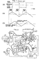
- FIG. 2 shows the whole engine control system. Referring to Fig. 2, sucked air is fed to a cylinder 8 through an air cleaner 2, a throttle chamber 4, and an intake pipe 6. The combusion gas in the cylinder 8 is exhausted .to the air through an exhaust pipe 10. The oxygen concentration of the exhaust gases is detected by an 0 2 sensor 11.
- an injector 12 which injects fuel. This fuel is then atomized within the passage of throttle chamber 4 through which air is flowed and as a result the mixture of fuel and sucked air is formed and then fed through the intake pipe 6 and through an intake valve 20 being open, to the combustion chamber of the cylinder 8.
- Throttle valves 14 and 16 are provided near the outlet of the injector 12.
- the throttle valve 14 is constructed to be mechanically connected to the accelerator pedal which the operator drives.
- the throttle valve 16 is so arranged as to be driven by a diaphragm 18. When the amount of air flow is small, the valve 16 is completely closed, and as it increases, the negative pressure on the diaphragm 18 increases to gradually open the valve 16, preventing the suction resistance from increasing.
- An air-flow passage 22 is provided above the throttle valves 14 and 16 in the throttle chamber 4.
- an electric heater 24 which forms a hot-wire type air-flow meter responsive to the rate of the air flow to produce an electric signal which is determined by the relation between the rate of air flow and the amount of heat from the heater 24. Since the heater 24 is provided in the air-flow passage 22, it can be protected from the high-temperature gas produced upon back fire in the cylinder 8 and prevented from the contamination by dust and the like in the sucked air.
- the air-flow passage 22 has its outlet near the narrowest portion of the venturi tube and its inlet on the upstream side thereof.
- the fuel in the injector 12 is fed from a fuel tank 30 to a fuel-pressure regulator 38 through a fuel pump 32, a fuel damper 34 and a filter 36.
- the fuel pressure regulator 38 supplies fuel under pressure to the injector 12 through a pipe 40 and also feeds fuel back to the fuel tank 30 through a. return pipe 42 in order that the difference between the pressure in the intake pipe 6 into which fuel is injected from the injection 12, and the pressure of the fuel-fed to the injector 12 can be maintained constant.
- the mixture of fuel and air sucked through the intake valve 20 is compressed by a piston 50 and then burnt by sparking of an ignition plug 52.
- the combustion of the mixture is converted to a kinetic energy.
- the cylinder 8 is cooled by cooling water 54 and the resulting temperature of the used cooling water is measured by a water temperature sensor 56 and used as engine temperature.
- the ignition plug 52 is supplied with a high voltage from an ignition coil 58 in synchronism with the ignition operation.
- crankshaft not shown is provided with a crank angle sensor which generates a reference angle signal and apposition signal at every reference crank angles and at every constant angles (for example, 0.5 degree) as the engine rotates, respectively.
- the electric signals from the output of this crank angle sensor, outputs of the water temperature sensor 56 and heater 24 are supplied to a control circuit 64 formed of a microcomputer or the like and arithmetically processed by the control circuit 64 the output of which is used to drive the injector 12 and ignition coil 58.
- a bypass 26 communicating with the intake pipe 6 is provided over the throttle valve 16 in the throttle chamber 4, and this bypass 26 is provided with a bypass valve 62 to_be_controlled to open and close.
- the drive portion of this bypass valve 62 is supplied with a signal from the control circuit 64 so that the valve 62 is controlled to open and close.
- the bypass valve 62 faces to the bypass 26 going around the throttle valve 16 and is controlled to open and close by a pulse current.
- This bypass valve 62 changes the cross-sectional area of the bypass 26 in response to the amount that the valve is lifted by the output of the control circuit 64 through the driving system. That is, the control circuit 64 generates an open/close period signal for controlling the driving system to supply a control signal to the drive portion of the bypass valve 62 thereby adjusting the amount of lifting the bypass valve 62.
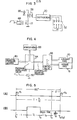
- Fig. 3 is a diagram of the ignition device in Fig. 2.
- a pulse current is supplied through an amplifier 68 to a power transistor 72 to make it conductive. Consequently, current is flowed through the primary of an ignition coil 68 from a battery 66. When this pulse current falls off, the transistor 72 is nonconductive and hence a high voltage is induced in the secondary of the ignition coil 58.
- This induced high voltage is distributed to each of the ignition plugs 52 which is disposed in each cylinder of the engine, in synchronism with the rotation of engine.
- F ig. 4 illustrates an exhaust gas recirculation (hereinafter, referred to as EGR) system.
- EGR exhaust gas recirculation
- a constant negative pressure from a negative pressure source 80 is exerted through a pressure control valve 84 onto a control valve 86.
- the pressure control valve 84 controls the constant negative pressure of the negative pressure soruce 80 to be divided into partial pressures on the atmosphere 88 and the control valve 86, the ratio of which is controlled in accordance with the duty ratio of the repetitive pulse applied to the pressure control valve 84 from a transistor 90.
- the negative pressure applied on the control valve 86 is determined by the on-duty ratio of the pulse from the transistor 90.
- the controlled negative pressure from the valve 84 controls the amount of EGR from the exhaust pipe 10 to the intake pipe 6.
- Time t 3 is the closing time of the intake valve 20 of the corresponding cylinder.
- the valve closing angle is fixed at a predetermined crank angle 6 from the reference postion where the reference pulse R 2 is produced.
- a time duration t D from time t 2 to time t 3 represents the dead time described above.
- the finally injected fuel injected at time t 2 is delivered in the intake pipe 6 and passed through the intake valve 20 at time t 3 , at which the intake valve 20 is closed.
- the dead time t D is fluctuated to a great extent depending on the engine operating condition.
- the beginning time (t l ) of the fuel injection is altered in accordance with the fluctuations of the dead time t D , almost all of the fuel injected during the period T i is surely supplied into the combustion chamber in the form of air-fuel mixture under any operating conditions of the engine, whereby accurate fuel control can be effected.
- the mixture is supplied into the combustion chamber at appropriate timing, stratified charge of mixture enriching toward the spark plug side is formed in the combustion chamber. By this stratified charge good combustion of the mixture is obtained which contributes exhaust gas purification.
- the dead time t D can be obtained from the following equation: where L 1 is intake manifold length and v A is intake air flow rate which is direct proportional to an intake air amount Q A . Therefore, the dead time t D is obtained by detecting the intake air amount Q A or the intake air flow rate v A .
- the beginning time t 1 of the fuel injection is determined as a time point preceeding from the occurrence of the reference angle pulse R 2 by the total of the fuel injection duration T i , the dead time duration t D and the time duration t ee Practically, however, the beginning time t 1 is determined by calculating a time duration t after the occurrence of the reference angle signal R 1 which preceeds the injection, according to the following equation:
- time t 3 coincides with the intake valve closing time in Fig. 5, it is not limited to the valve closing time, but may be a time point related to the valve closing time, say near to the intake valve closing time. Further, time t 3 may be variable in accordance with a particular characteristic of engines. Where the manifold length L 1 is considerably different depending on the cylinders of a multi-cylinder engine, two or more dead times may be employed.
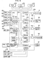
- Fig. 6 shows the whole construction of the control system, which comprises a CPU 102, a read-only memory (hereinafter, referred to as ROM) 104, a random access memory (hereinafter, referred to as RAM) 106 and an input/ output unit 108.
- the CPU 102 arithmetically processes the input data from the input/output unit 108 and returns the results to the unit 108 in accordance with various programs stored in the ROM 104.
- the RAM 106 serves to store all intermediate results of this computation.
- Bus lines 110 which comprise a data bus, a control bus and an address bus, interconnect the CPU 102, ROM 104, RAM 106 and input/output unit 108 to carry various kinds of data therebetween.
- the input/output unit 108 comprises a first analog-to-digital converter (hereinafter, referred to as ADC1), a second analog-to-digital converter (hereinafter, referred to as ADC2), an angle signal processing circuit 126, and a discrete input/output circuit for 1-bit, information hereinafter, referred to as DIO).
- ADC1 first analog-to-digital converter
- ADC2 second analog-to-digital converter
- DIO discrete input/output circuit for 1-bit, information hereinafter, referred to as DIO
- the ADC1 includes: a multiplexer (hereinafter, referred to as M PX ) 120 which is supplied with the outputs from a battery voltage detecting sensor 132 (VBS), a cooling water temperature sensor 56 (TWS), an atmosphere temperature sensor 112 (TAS), a regulation voltage generator 114 (VRS), a throttle angle sensor 116 (6THS), and a ⁇ sensor 118 (XS); an analog-to-digital converter 122 (ADC) to which one-of the outputs is applied from the M PX 120; and a register 124 (REG) which holds the digital value from the ADC.
- M PX multiplexer
- the ADC2 includes an analog-to-digital converter 128 (ADC) which is supplied with the output from a flow sensor 24 (AFS), and a register 130 (REG) in which the output of the ADC is set.
- ADC analog-to-digital converter 128
- ADC analog-to-digital converter 128
- FAS flow sensor 24
- REG register 130
- An angle sensor 146 produces a signal of a reference crank angle, for example, 180 degrees (REF) and a signal indicative of a very small angle, for example, 0.5-degree crank angle (POS) and supplies them.to an angle signal processing circuit 126, where they are shaped in their waveforms.
- the DIO is supplied with the outputs from an idle switch 148 (IDLE-SW), a top gear switch 150 (TOP-SW) and a starter switch 152 (START-SW).
- ILE-SW idle switch 148
- TOP-SW top gear switch 150
- STT-SW starter switch 152
- An injector control circuit converts the digital values of the calculated results to a pulse output.
- the INJC 134 makes a pulse of the width corresponding to the amount of fuel injection and supplies it through an AND gate 136 to the injector 12.
- An ignition pulse generator 138 comprises a register (ADV) for storing the ignition time and a register (DWL) for storing the time the primary current starts to flow through the primary of the ignition coil.
- the CPU sets such data in the ADV and DWL.
- the pulse based on the data is supplied from the IGNC through an AND gate 140 to the amplifier 68.
- the degree to which the bypass valve 62 opens is controlled by the pulse applied from a control circuit (ISCC) 142 through an AND gate 144.
- the ISCC 142 has a register ISCD for storing the pulse width and a register (ISCP) for storing the period of the repetitive pulse.
- An EGR amount control pulse generator 154 which permits the transistor 90 to control the EGR control valve 86 shown in Fig. 3, comprises a register EGRD for storing the duty ratio of the pulse and a register EGRP for storing the period of the pulse.
- the output pulse from the EGRC is applied through an AND gate 156 to the transistor 90.
- the input/output signal of 1 bit is controlled by the circuit DIO.
- the input signals thereto are the IDLE-SW, TOP-SW, and START-SW signals as described above.
- the output signal is a pulse output signal for driving the fuel pump.
- the DIO includes a register DDR for determining whether its terminals are used as input or output terminals, and a register DOUT for latching the output data.
- a register 160 is a register (MOD) for holding an instruction to take various conditions within the input/output circuit 108.
- MOD a register
- the AND gates 136, 140, 144 and 156 can all be turned on or off by setting an instruction in this register.
- the INJC, IGNC and ISCC can be controlled to stop or produce output by setting an instruction in the MOD register 160.
- Fig. 7 shows a specific example of the program system of a control circuit in Fig. 6.
- the operating system program OS comprises the initial processing program 202, the interruption processing program 206, the task dispatcher 208 and the macro processing program 228.
- the interruption processing program 206 includes various different interruption programs.
- initial interruption program (INTL interruption processing) 602
- initial interrupt is caused half-the-number-of-engine- cylinders times, or two times per engine revolution for 4 cylinder engine, by the initial interrupt signal produced in synchronism with engine rotation.
- the fuel injection time calculated at EGI, task 612 is set up in the EGI register of the input/output interface circuit 108.
- An A/D conversion interrupt process 604 includes two types: A/D converter-1 interrupt. (ADC1) and A/D converter-2 interrupt (ADC2).
- A/D converter 1 has precision of 8 bits and is supplied with source voltage, cooling water temperature, sucked air temperature, adjustment of engine and so on.
- this A/D converter 1 specifies one of such inputs to the multiplexer 120 and at the same time starts to convert. After completion of the conversion, it produces ADC1 interrupt, which is used only before cranking.
- the A/D converter 128 is supplied with an air flow input, and ADC2 interrupt is produced after end of conversion. This interrupt is also used only before cranking.
- an INTV interrupt signal is produced for example, at every 10 ms set up in an INTV register and used as a time monitor fundamental signal for task to be started with a constant period. This interrupt signal is used to update the software timer, and permits the task reached a specified period to start.
- an engine stop interrupt processing program (ENST interrupt processing program) 608 which detects the condition of engine stop, counting starts when the INTL interrupt signal is detected, and then an ENST interrupt occurs when the next INTL interrupt signal cannot be detected within a predetermined time, for example, 1 second.
- the task group started by the different interrupts mentioned before is as follows: amount-of-air-signal processing task (AS task), fuel injection control task (EGI task) and initial monitor task (MONIT task) for task level 0; AD1 input task (ADIN1 task), and time coefficient processing task (AFSIA task) for task level 1; and idle speed control task (ISC task), compensation calculation task (HOSEI task) and initial preprocess task (ISTRT task) for task level 2.
- AS task amount-of-air-signal processing task
- EGI task fuel injection control task
- MONIT task initial monitor task
- AD1 input task AD1 input task
- AFSIA task time coefficient processing task
- ISC task idle speed control task
- HOSEI task compensation calculation task
- ISTRT task initial preprocess task
- Table 2 shows assignment of each task level and task functions.
- the start periods of the tasks to be started by different interrupts are predetermined as is evident from Table 2, and stored in ROM 104.
- the INTL interrupt process will be described which is one example of processing signals v from the hot-wire flow sensor.
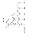
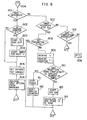
- the signals v from the hot-wire flow sensor are received by the INTL interruption at different timing for three modes of the revolution speed of engine. That is, as shown in Fig. 8, the revolution speed N of 4-cylinder engine is smaller than 1600 rpm for mode 0, is in the range from 1600 rpm to 3200 rpm, inclusive for mode 1, and is larger than 3200 rpm for mode 2. Thus, one intake stroke corresponds to a crank rotation angle of 180°. In this embodiment, the N is 1600 rpm for mode 0, 3200 rpm for mode 1 and 6400 rpm for mode 2. Thus, the engine in mode 1 rotates through twice the angle in mode 0 and it in mode 2 rotates through four times the angle in mode 0, or twice the angle in mode 1 as shown in Fig. 8.
- 10 samples are taken in the mode 0 of engine. That is, in mode 0 sampling is mode at each 18° of crank rotation angle, in mode 1 sampling is made at each 36° of crank angle because the revolution speed N is twice that in mode 0 and in mode 2 sampling is made at each 72° of crank angle because the revolution speed N is four times that in mode 0. Therefore, at a crank rotation angle per intake stroke, the same amount of data as in mode 0 is sampled in each mode. If the interval of sampling data is changed in proportion to the revolution speed of engine, the data processing time is constant regardless of change of revolution speed.
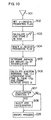
- Fig. 9 is a flowchart of the INTL interrupt processing for sampling the. signal from the hot-wire-flow sensor.
- step 801 decision is made of whether an INTL interrupt occurred or not. If the decision is YES, the program goes to step 802, where decision is made of whether the counter for counting the number of receiving times of analog value v (hereinafter referred to as analog counter) is at zero or not. If the decision is YES, the program further goes to step 803, where the A/D converter is started to introduce the amount of air, v.. When the.amount of air, v is started to be sucked, the program progresses to step 804, where the timer is set at a time when the next amount of air, v is sucked, in accordance with the revolution speed of engine and the mode thereof.
- step 804 When at step 804 the timer is set, the program goes to step 805, where EGIREG, IGNREG are set. At step 806, the interrupt for only INTLIRQ is released from inhibition. Then, the INTL interrupt processing program ends. If at step 802 the analog counter is not at zero, the program goes to step 805.
- step 801 If at step 801 no INTL interrupt occurs, the program goes to step 807, where decision is made of whether it is the timer interrupt for QA or not. If the decision is YES, the program goes to step 808, where decision is made of whether the timer interrupt inhibit flag is set or not. If the decision is YES, the program ends. If it is NO, the program goes to step 809, where the amount of air, v is introduced so that the analog counter is incremented-by 1. At step 810, decision is made of whether the suction of v has been completed or nt (wherther the contents of the analog counter shows a specified number of times that the suction occurs). If the decision is YES, the program goes to step 811, where the timer is stopped. Then, at step 812 the analog counter is reset.
- step 810 the suction is not completed, the program goes to step 813, where the A/D converter 128 is started.
- Them, at step 814, v 2 is calculated and stored in RAM.
- step 807 If at step 807 the interrupt is decided not to be timer interrupt, the program goes to step 815, where decision is made of whether or not it is ADC interrupt. If at step 815 the decision is YES, the program is returned from the interrupt. If at step 815 it is not AD interrupt or at step 816 IST is not 1, the program goes to the INTV interrupt process 606 in Fig. 7.
- the task of amount-of-air signal process (AC) 610 as shown in Fig. 7 will hereinafter be described.
- the amount-of-air signal process task is started at step 901 as shown in Fig. 10.
- the program goes to step 902, where v-suction inhibit flag is set.
- (v 2 ) 2 is calculated to obtain the value of an air flow amount (Q A ) and stored in RAM, since the output (v) of a hot-wire type air-flow sensor is directly proportional to the fourth root of the air flow amount (Q A ) .
- the suction inhibit flag is reset.
- step 905 When the flag is reset, the program goes to step 905, where the value (v 2 ) 2 stored in RAM at step 903 is accumulated and averaged. Then, at step 906, injection timing considering fuel transport lag or dead time t D is calculated from 1/Q A and revolution speed N of engine as described previously.
- step 907 decision is made of whether or not it shows acceleration state of engine. If at step 907 the decision is YES, the program goes to step 908, where acceleration injection is made. If at step 907 it is NO, the program goes to the macro process 228 in Fig. 7 after acceleration injection at step 908.
- the task of fuel injection control (EGI) 621 shown in Fig. 7 will hereinafter be described.
- the fuel injection control task as shown in Fig. 11 is started at step 950.
- a basic fuel injection time t i is calculated from average amount of air Q A and revolution speed N of engine.
- decision is made of whether or not the signal from the oxygen sensor (0 2 sensor) has crossed the theoretical air-fuel ratio. If at step 954 the decision is YES, the program goes to step 955, where an air-fuel ratio correction coefficient ⁇ ix at the time when the theoretical air-fuel ratio is determined from the reciprocal, 1/Q A of the average air amount, is read from the RAM as a..
- step 954 the program goes to step 952.
- a fuel injection time Ti is calculated by multiplying the basic fuel injection time ti by an air-fuel ratio correction coefficient ai.
- the air-fuel ratio correction coefficient a i is stored in RAM.
- the fuel injection time Ti is stored in a register. Then, the program progresses to the macro process 228 in Fig. 7.
- Fig. 12 shows a generator circuit for IRQ.
- a register 735, counter 736, comparator 737 and flip-flop 738 constitute a generator circuit for INTV IRQ.
- the register 735 is set the period of INTV IRQ to be generated, for example, in this embodiment, 10 ms.
- a clock pulse is set in the counter 736 and, when its count reaches the contents of the register 735, it sets the flip-flop 738. At this time, the counter 736 is cleared and again starts to count. Therefore, the INTV IRQ is generated at intervals of constant time (10 msec).
- a register 741, counter 742, comparator 743, and flip-flop 744 constitute a generator circuit for ENST IRQ by which engine stop is detected.
- the comparator 743 sets the flip-flop 744, thus ENST IRQ being generated therefrom.
- the REF pulse is generated at intervals of constant crank angle from the crank angle sensor during engine rotation, to clear the counter 742, which thus does not reach the contents of the register 741 so that no ENST IRQ is generated.
- a signal for permitting the IRQ to be produced or not is set in flip-flops 739, 745, 762 and 766. If "H" levels is set in the flip-flops 739,745, 762 and 766, AND gates 748, 750, 770 and 772 are gated open. At this time, when IRQ is generated, it readily appears from an OR gate 751.
- the IRQ can be inhibited from generation or released from the inhibition by supplying "H” or "L” level to each of the flip-flops 739, 745, 762 and 766.
- the contents of the flip-flops 740, 746, 764 and 768 is supplied to the CPU, which thus can find the cause of IRQ generation.
- the IRQ signal is required to be cleared, and thus the CPU clears the corresponding one of the flip-flops 740, 746, 764 and 768 to that IRQ.
- the amount of control upon level change can be controlled to achieve the theoretical air-fuel ratio, and in addition, for deviation to exceeding rich or lean concentration of fuel, modifying amount of control is always added to cancel the deviation out. Therefore, unlike the prior art, the control for excessively rich concentration of fuel is made to effectively decrease the concentration. Also, since the loop gain can be increased for the same hanting limit, the control gain is increased to decrease harmful exhaust gas and achieve the stability of operation of engine.
- control apparatus as described above is able to stabilize the fuel injection of internal combustion engine and increase response.
Abstract
Description
- This invention relates to fuel control apparatus for internal combustion engine, and particularly to a fuel injection control apparatus for internal combustion engine capable of correcting for the response lag in fuel suction path.
- A conventional fuel control apparatus for internal combustion engine has a sensor responsive to a particular exhaust gas concentration in the exhaust pipe to produce a signal, which is fed back to the fuel injection control apparatus thereby to control the air-fuel ratio. In particular, there is generally used a method in which a solid electrolyte such as zirconium oxide is used to detect partial pressure of oxygen in the exhaust gases and the air-fuel ratio is controlled to be a stoichiometric equilibrium point (hereinafter, called the theoretical air-fuel ratio).
- Figs. 1A, 1B and 1C is an explanatory diagram for the conventional, generally used control method.
- Fig. 1A shows the output of an exhaust sensor (oxygen sensor or 02 sensor) such as a material mainly including zirconium oxide for detecting the change of partial pressure of oxygen.
- This sensor detects partial pressure of oxygen to produce high-level output when the fuel is rich or low-level output when it is lean, the theoretical air-fuel ratio lying between these high and low levels. Fig. 1B shows the amount that the air-fuel ratio adjusting device adjusts. This device acts to incease or decrease the air-fuel ratio at a uniform rate with time and the switching between the increase and decrease is made when the output of the oxygen sensor has crossed the reference level. That is, when the sensor changes its output from lean-fuel level to rich-fuel level, the device adjusts to decrease the air-fuel ratio, and when it changes its output from rich-fuel level to lean-fuel level, the device adjusts to increase the ratio. Because of such adjustment, the engine actually wastes time upon feeding fuel and air from fuel supply device to combustion chamber. The air-fuel ratio at which the mixture of fuel and air is actually burnt in the combustion chamber has a phase lag shown in Fig. 1C, corresponding to waste time or dead time on the intake side when the adjustment is made as shown in Fig. 1B. There is dead time on the exhaust side between the completion of fuel and the responding of oxygen sensor, but it is usually smaller than on the intake side. The peaks of the wave of Fig. 1C show excessive values over the average value thereof. The large peak increases harmful components in the exhaust gases and brings about instability in driving.
- Thus, since the air-fuel ratio is determined from the partial pressure of oxygen in the exhaust gases afer combustion, response lag is caused to trouble general feed-back control, and dead time is taken in association with the intake pipe, combustion and exhausting. Consequently, the increase of loop gain in control system causes hanting in the air-fuel ratio and hence brings about an extremely unstable combustion state to increase harmful exhaust gases. The decrease of loop gain makes the response of the system very slow, causing long transient conditions unsatisfactory for the internal combustion engine. Also, the air-fuel ratio is fluctuated with the result that harmful exhaust gases are increased. Therefore, it is necessary to increase the loop gain to limit at which no hanting is caused. However, lag time of system and dead time are fluctuated to a great extent depending on the driving condition of engine, and thus makes it difficult to set up a proper gain.
- Further, the fact that the dead time is fluctuated to a great extent depending on the operating condition of the engine means that a time duration from the time when fuel is-injected by an injector to the time when the injected fuel is reached to the combustion chamber of a corresponding cylinder through the fuel intake path is fluctuated to a great extent depending on the operating condition of the engine. In the fuel injection control apparatus hitherto proposed, the fuel injection timing is not controlled by considering such fluctuations of the dead time, and hence the conventional fuel control apparatus have a disadvantage that a desired fuel amount cannot necessarily be supplied into the combustion chamber when the engine operating condition is changed, whereby the fuel control can not precisely be carried out.
- It is an object of the invention to provide a fuel injection control apparatus for internal combustion engine capable of controlling engine with high stability and response.
- According to this invention,.since the amount that the air-fuel ratio is adjusted is stored and delayed and it is used as a reference to modified amount of adjustment, excessive amount of adjustment associated with dead time is reduced and the limit at which hanting is caused is extended under high loop gain so that the variation of the air-fuel ratio is suppressed. Thus, harmful exhaust gases are prevented from occuring and high response is obtained. In other words, dead time in the total distance of a known system is calculated from the output of a hot wire flow sensor, or the flow rate of intake air, and the amount of adjustment delayed by that dead time is sampled upon level change of output from the oxygen sensor to be used as a reference to control.
- These and other objects will become more apparent when a preferred embodiment of the present invention is considered in connection with the accompanying drawings in which:
- Figs. lA, 1B and 1C are explanatory diagrams useful for explaining the conventional fuel control method;
- Fig. 2 shows the whole engine control system;
- Fig. 3 shows the ignition device in Fig. 2;
- Fig. 4 is a diagram useful for explaining the exhaust gas recirculation system;
- Fig.-5 is a timing chart useful for explaining the principle of the present invention;
- Fig. 6 shows the whole control system for engine;
- Fig. 7 is a specific flowchart of Fig. 6;
- Fig. 8 is a timing chart of sampling the output voltage from the hot wire;
- Fig. 9 is a flowchart of INTL interrupt process for sampling the signal from the hot wire flow sensor;
- Fig. 10 is a flowchart of air amount signal processing task;
- Fig. 11 is a flowchart of fuel injection control task; and
- Fig. 12 shows a generator for interrupt IRQ.
- An embodiment of this invention will hereinafter be described. Fig. 2 shows the whole engine control system. Referring to Fig. 2, sucked air is fed to a
cylinder 8 through anair cleaner 2, athrottle chamber 4, and anintake pipe 6. The combusion gas in thecylinder 8 is exhausted .to the air through anexhaust pipe 10. The oxygen concentration of the exhaust gases is detected by an 02 sensor 11. - In the
throttle chamber 4, is provided aninjector 12, which injects fuel. This fuel is then atomized within the passage ofthrottle chamber 4 through which air is flowed and as a result the mixture of fuel and sucked air is formed and then fed through theintake pipe 6 and through anintake valve 20 being open, to the combustion chamber of thecylinder 8. -
Throttle valves 14 and 16 are provided near the outlet of theinjector 12. Thethrottle valve 14 is constructed to be mechanically connected to the accelerator pedal which the operator drives. The throttle valve 16 is so arranged as to be driven by adiaphragm 18. When the amount of air flow is small, the valve 16 is completely closed, and as it increases, the negative pressure on thediaphragm 18 increases to gradually open the valve 16, preventing the suction resistance from increasing. - An air-
flow passage 22 is provided above thethrottle valves 14 and 16 in thethrottle chamber 4. In this air-flow passage 22 is provided anelectric heater 24 which forms a hot-wire type air-flow meter responsive to the rate of the air flow to produce an electric signal which is determined by the relation between the rate of air flow and the amount of heat from theheater 24. Since theheater 24 is provided in the air-flow passage 22, it can be protected from the high-temperature gas produced upon back fire in thecylinder 8 and prevented from the contamination by dust and the like in the sucked air. The air-flow passage 22 has its outlet near the narrowest portion of the venturi tube and its inlet on the upstream side thereof. - The fuel in the
injector 12 is fed from a fuel tank 30 to a fuel-pressure regulator 38 through afuel pump 32, afuel damper 34 and afilter 36. Thefuel pressure regulator 38 supplies fuel under pressure to theinjector 12 through apipe 40 and also feeds fuel back to the fuel tank 30 through a. returnpipe 42 in order that the difference between the pressure in theintake pipe 6 into which fuel is injected from theinjection 12, and the pressure of the fuel-fed to theinjector 12 can be maintained constant. - The mixture of fuel and air sucked through the
intake valve 20 is compressed by apiston 50 and then burnt by sparking of anignition plug 52. The combustion of the mixture is converted to a kinetic energy. Thecylinder 8 is cooled by coolingwater 54 and the resulting temperature of the used cooling water is measured by awater temperature sensor 56 and used as engine temperature. The ignition plug 52 is supplied with a high voltage from anignition coil 58 in synchronism with the ignition operation. - In addition, the crankshaft not shown is provided with a crank angle sensor which generates a reference angle signal and apposition signal at every reference crank angles and at every constant angles (for example, 0.5 degree) as the engine rotates, respectively.
- The electric signals from the output of this crank angle sensor, outputs of the
water temperature sensor 56 andheater 24 are supplied to acontrol circuit 64 formed of a microcomputer or the like and arithmetically processed by thecontrol circuit 64 the output of which is used to drive theinjector 12 andignition coil 58. - In the engine system to be controlled as described above, a
bypass 26 communicating with theintake pipe 6 is provided over the throttle valve 16 in thethrottle chamber 4, and thisbypass 26 is provided with abypass valve 62 to_be_controlled to open and close. The drive portion of thisbypass valve 62 is supplied with a signal from thecontrol circuit 64 so that thevalve 62 is controlled to open and close. - The
bypass valve 62 faces to thebypass 26 going around the throttle valve 16 and is controlled to open and close by a pulse current. Thisbypass valve 62 changes the cross-sectional area of thebypass 26 in response to the amount that the valve is lifted by the output of thecontrol circuit 64 through the driving system. That is, thecontrol circuit 64 generates an open/close period signal for controlling the driving system to supply a control signal to the drive portion of thebypass valve 62 thereby adjusting the amount of lifting thebypass valve 62. - Fig. 3 is a diagram of the ignition device in Fig. 2. A pulse current is supplied through an
amplifier 68 to apower transistor 72 to make it conductive. Consequently, current is flowed through the primary of anignition coil 68 from abattery 66. When this pulse current falls off, thetransistor 72 is nonconductive and hence a high voltage is induced in the secondary of theignition coil 58. - This induced high voltage is distributed to each of the ignition plugs 52 which is disposed in each cylinder of the engine, in synchronism with the rotation of engine.
- Fig. 4 illustrates an exhaust gas recirculation (hereinafter, referred to as EGR) system. A constant negative pressure from a
negative pressure source 80 is exerted through apressure control valve 84 onto acontrol valve 86. Thepressure control valve 84 controls the constant negative pressure of thenegative pressure soruce 80 to be divided into partial pressures on theatmosphere 88 and thecontrol valve 86, the ratio of which is controlled in accordance with the duty ratio of the repetitive pulse applied to thepressure control valve 84 from atransistor 90. Thus, the negative pressure applied on thecontrol valve 86 is determined by the on-duty ratio of the pulse from thetransistor 90. The controlled negative pressure from thevalve 84 controls the amount of EGR from theexhaust pipe 10 to theintake pipe 6. - The control of fuel injection timing in the above-contructed engine control system will now be described referring to the timing chart shown in Fig. 5. In (A) of Fig. 5, there is shown a waveform of reference angle pulses R1 and R2 each thereof being produced at every predetermined reference crank angle, 180° in this case. When the engine rotation speed N is determined, a period of time T between the reference pulses can be obtained from the equation, T = K/N, where K is a constant. In (B) of Fig. 5, there is shown a waveform of an injection pulse for the
injector 12, and in this case the fuel injection by theinjector 12 begins at time t1 and terminates at time t2. Namely, a time duration T represents the fuel injection period. Time t3 is the closing time of theintake valve 20 of the corresponding cylinder. The valve closing angle is fixed at apredetermined crank angle 6 from the reference postion where the reference pulse R2 is produced. Thus, when the engine rotation speed N is determined, a time duration tθ from the intake valve closing time (t3) to the occurence of the reference pulse R2 can be obtained from the equation, tθ = (θ/180) x T. A time duration tD from time t2 to time t3 represents the dead time described above. The finally injected fuel injected at time t2 is delivered in theintake pipe 6 and passed through theintake valve 20 at time t3, at which theintake valve 20 is closed. As describe above, the dead time tD is fluctuated to a great extent depending on the engine operating condition. According to the present invention, since the beginning time (tl) of the fuel injection is altered in accordance with the fluctuations of the dead time tD, almost all of the fuel injected during the period Ti is surely supplied into the combustion chamber in the form of air-fuel mixture under any operating conditions of the engine, whereby accurate fuel control can be effected. Moreover, since the mixture is supplied into the combustion chamber at appropriate timing, stratified charge of mixture enriching toward the spark plug side is formed in the combustion chamber. By this stratified charge good combustion of the mixture is obtained which contributes exhaust gas purification. - The dead time tD can be obtained from the following equation:

- The beginning time t1 of the fuel injection is determined as a time point preceeding from the occurrence of the reference angle pulse R2 by the total of the fuel injection duration Ti, the dead time duration tD and the time duration tee Practically, however, the beginning time t1 is determined by calculating a time duration t after the occurrence of the reference angle signal R1 which preceeds the injection, according to the following equation:

- Although time t3 coincides with the intake valve closing time in Fig. 5, it is not limited to the valve closing time, but may be a time point related to the valve closing time, say near to the intake valve closing time. Further, time t3 may be variable in accordance with a particular characteristic of engines. Where the manifold length L1 is considerably different depending on the cylinders of a multi-cylinder engine, two or more dead times may be employed.
- Fig. 6 shows the whole construction of the control system, which comprises a
CPU 102, a read-only memory (hereinafter, referred to as ROM) 104, a random access memory (hereinafter, referred to as RAM) 106 and an input/output unit 108. TheCPU 102 arithmetically processes the input data from the input/output unit 108 and returns the results to theunit 108 in accordance with various programs stored in theROM 104. TheRAM 106 serves to store all intermediate results of this computation.Bus lines 110, which comprise a data bus, a control bus and an address bus, interconnect theCPU 102,ROM 104,RAM 106 and input/output unit 108 to carry various kinds of data therebetween. - The input/
output unit 108 comprises a first analog-to-digital converter (hereinafter, referred to as ADC1), a second analog-to-digital converter (hereinafter, referred to as ADC2), an anglesignal processing circuit 126, and a discrete input/output circuit for 1-bit, information hereinafter, referred to as DIO). - The ADC1 includes: a multiplexer (hereinafter, referred to as MPX) 120 which is supplied with the outputs from a battery voltage detecting sensor 132 (VBS), a cooling water temperature sensor 56 (TWS), an atmosphere temperature sensor 112 (TAS), a regulation voltage generator 114 (VRS), a throttle angle sensor 116 (6THS), and a λ sensor 118 (XS); an analog-to-digital converter 122 (ADC) to which one-of the outputs is applied from the M
PX 120; and a register 124 (REG) which holds the digital value from the ADC. - The ADC2 includes an analog-to-digital converter 128 (ADC) which is supplied with the output from a flow sensor 24 (AFS), and a register 130 (REG) in which the output of the ADC is set.
- An angle sensor 146 (ANGS) produces a signal of a reference crank angle, for example, 180 degrees (REF) and a signal indicative of a very small angle, for example, 0.5-degree crank angle (POS) and supplies them.to an angle
signal processing circuit 126, where they are shaped in their waveforms. - The DIO is supplied with the outputs from an idle switch 148 (IDLE-SW), a top gear switch 150 (TOP-SW) and a starter switch 152 (START-SW).
- Description will hereinafter be described of a pulse output circuit to which the calculated results are supplied from the CPU, and objects to be controlled. An injector control circuit (INJC) converts the digital values of the calculated results to a pulse output. Thus, the
INJC 134 makes a pulse of the width corresponding to the amount of fuel injection and supplies it through an ANDgate 136 to theinjector 12. - An ignition pulse generator 138 (IGNC) comprises a register (ADV) for storing the ignition time and a register (DWL) for storing the time the primary current starts to flow through the primary of the ignition coil. The CPU sets such data in the ADV and DWL. The pulse based on the data is supplied from the IGNC through an AND
gate 140 to theamplifier 68. - The degree to which the
bypass valve 62 opens is controlled by the pulse applied from a control circuit (ISCC) 142 through an ANDgate 144. TheISCC 142 has a register ISCD for storing the pulse width and a register (ISCP) for storing the period of the repetitive pulse. - An EGR amount control pulse generator 154 (EGRC), which permits the
transistor 90 to control theEGR control valve 86 shown in Fig. 3, comprises a register EGRD for storing the duty ratio of the pulse and a register EGRP for storing the period of the pulse. The output pulse from the EGRC is applied through an ANDgate 156 to thetransistor 90. - The input/output signal of 1 bit is controlled by the circuit DIO. The input signals thereto are the IDLE-SW, TOP-SW, and START-SW signals as described above. The output signal is a pulse output signal for driving the fuel pump. The DIO includes a register DDR for determining whether its terminals are used as input or output terminals, and a register DOUT for latching the output data.
- A
register 160 is a register (MOD) for holding an instruction to take various conditions within the input/output circuit 108. For example, the ANDgates MOD register 160. - Fig. 7 shows a specific example of the program system of a control circuit in Fig. 6. In Fig. 7, the operating system program OS comprises the
initial processing program 202, the interruption processing program 206, thetask dispatcher 208 and themacro processing program 228. - The interruption processing program 206 includes various different interruption programs. In an initial interruption program (INTL interruption processing) 602, initial interrupt is caused half-the-number-of-engine- cylinders times, or two times per engine revolution for 4 cylinder engine, by the initial interrupt signal produced in synchronism with engine rotation. The fuel injection time calculated at EGI,
task 612 is set up in the EGI register of the input/output interface circuit 108. An A/D conversion interruptprocess 604 includes two types: A/D converter-1 interrupt. (ADC1) and A/D converter-2 interrupt (ADC2). The A/D converter 1 has precision of 8 bits and is supplied with source voltage, cooling water temperature, sucked air temperature, adjustment of engine and so on. Also, this A/D converter 1 specifies one of such inputs to themultiplexer 120 and at the same time starts to convert. After completion of the conversion, it produces ADC1 interrupt, which is used only before cranking. The A/D converter 128 is supplied with an air flow input, and ADC2 interrupt is produced after end of conversion. This interrupt is also used only before cranking. - In an interval interrupt processing program (INTV interrupt processing program) 606, an INTV interrupt signal is produced for example, at every 10 ms set up in an INTV register and used as a time monitor fundamental signal for task to be started with a constant period. This interrupt signal is used to update the software timer, and permits the task reached a specified period to start. In an engine stop interrupt processing program (ENST interrupt processing program) 608 which detects the condition of engine stop, counting starts when the INTL interrupt signal is detected, and then an ENST interrupt occurs when the next INTL interrupt signal cannot be detected within a predetermined time, for example, 1 second. If the INTL interrupt signal cannot be detected after 3 ENST interrupts, for example, after lapse of 3 seconds, it is decided that the engine stopped, and supply of current to ignition coil and fuel pump is stopped. After these processes, standby is kept until a
start switch 152 is turned on. Table 1 shows the summary of process for the causes of the interruptions. -

- In the
initial process program 202 andmacro process program 228, the above processes are performed. - The task group started by the different interrupts mentioned before is as follows: amount-of-air-signal processing task (AS task), fuel injection control task (EGI task) and initial monitor task (MONIT task) for
task level 0; AD1 input task (ADIN1 task), and time coefficient processing task (AFSIA task) fortask level 1; and idle speed control task (ISC task), compensation calculation task (HOSEI task) and initial preprocess task (ISTRT task) fortask level 2. - Table 2 shows assignment of each task level and task functions.

- The start periods of the tasks to be started by different interrupts are predetermined as is evident from Table 2, and stored in
ROM 104. - The INTL interrupt process will be described which is one example of processing signals v from the hot-wire flow sensor.
- The signals v from the hot-wire flow sensor are received by the INTL interruption at different timing for three modes of the revolution speed of engine. That is, as shown in Fig. 8, the revolution speed N of 4-cylinder engine is smaller than 1600 rpm for
mode 0, is in the range from 1600 rpm to 3200 rpm, inclusive formode 1, and is larger than 3200 rpm formode 2. Thus, one intake stroke corresponds to a crank rotation angle of 180°. In this embodiment, the N is 1600 rpm formode 0, 3200 rpm formode 1 and 6400 rpm formode 2. Thus, the engine inmode 1 rotates through twice the angle inmode 0 and it inmode 2 rotates through four times the angle inmode 0, or twice the angle inmode 1 as shown in Fig. 8. - In this embodiment, 10 samples are taken in the
mode 0 of engine. That is, inmode 0 sampling is mode at each 18° of crank rotation angle, inmode 1 sampling is made at each 36° of crank angle because the revolution speed N is twice that inmode 0 and inmode 2 sampling is made at each 72° of crank angle because the revolution speed N is four times that inmode 0. Therefore, at a crank rotation angle per intake stroke, the same amount of data as inmode 0 is sampled in each mode. If the interval of sampling data is changed in proportion to the revolution speed of engine, the data processing time is constant regardless of change of revolution speed. - Fig. 9 is a flowchart of the INTL interrupt processing for sampling the. signal from the hot-wire-flow sensor.
- In Fig. 9, at step 801 decision is made of whether an INTL interrupt occurred or not. If the decision is YES, the program goes to step 802, where decision is made of whether the counter for counting the number of receiving times of analog value v (hereinafter referred to as analog counter) is at zero or not. If the decision is YES, the program further goes to step 803, where the A/D converter is started to introduce the amount of air, v.. When the.amount of air, v is started to be sucked, the program progresses to step 804, where the timer is set at a time when the next amount of air, v is sucked, in accordance with the revolution speed of engine and the mode thereof. When at
step 804 the timer is set, the program goes to step 805, where EGIREG, IGNREG are set. Atstep 806, the interrupt for only INTLIRQ is released from inhibition. Then, the INTL interrupt processing program ends. If atstep 802 the analog counter is not at zero, the program goes to step 805. - If at step 801 no INTL interrupt occurs, the program goes to step 807, where decision is made of whether it is the timer interrupt for QA or not. If the decision is YES, the program goes to step 808, where decision is made of whether the timer interrupt inhibit flag is set or not. If the decision is YES, the program ends. If it is NO, the program goes to step 809, where the amount of air, v is introduced so that the analog counter is incremented-by 1. At
step 810, decision is made of whether the suction of v has been completed or nt (wherther the contents of the analog counter shows a specified number of times that the suction occurs). If the decision is YES, the program goes to step 811, where the timer is stopped. Then, atstep 812 the analog counter is reset. - If at
step 810, the suction is not completed, the program goes to step 813, where the A/D converter 128 is started. Them, atstep 814, v2 is calculated and stored in RAM. - If at
step 807 the interrupt is decided not to be timer interrupt, the program goes to step 815, where decision is made of whether or not it is ADC interrupt. If atstep 815 the decision is YES, the program is returned from the interrupt. If atstep 815 it is not AD interrupt or at step 816 IST is not 1, the program goes to the INTV interruptprocess 606 in Fig. 7. - The task of amount-of-air signal process (AC) 610 as shown in Fig. 7 will hereinafter be described. The amount-of-air signal process task is started at
step 901 as shown in Fig. 10. When the task is started, the program goes to step 902, where v-suction inhibit flag is set. Then, atstep 903, (v2)2 is calculated to obtain the value of an air flow amount (QA) and stored in RAM, since the output (v) of a hot-wire type air-flow sensor is directly proportional to the fourth root of the air flow amount (QA) . At step 904, the suction inhibit flag is reset. When the flag is reset, the program goes to step 905, where the value (v2) 2 stored in RAM atstep 903 is accumulated and averaged. Then, atstep 906, injection timing considering fuel transport lag or dead time tD is calculated from 1/QA and revolution speed N of engine as described previously. Atstep 907 decision is made of whether or not it shows acceleration state of engine. If atstep 907 the decision is YES, the program goes to step 908, where acceleration injection is made. If atstep 907 it is NO, the program goes to themacro process 228 in Fig. 7 after acceleration injection atstep 908. - The task of fuel injection control (EGI) 621 shown in Fig. 7 will hereinafter be described. The fuel injection control task as shown in Fig. 11 is started at
step 950. Then, atstep 951, a basic fuel injection time ti is calculated from average amount of air QA and revolution speed N of engine. Then, atstep 954, decision is made of whether or not the signal from the oxygen sensor (02 sensor) has crossed the theoretical air-fuel ratio. If atstep 954 the decision is YES, the program goes to step 955, where an air-fuel ratio correction coefficient αix at the time when the theoretical air-fuel ratio is determined from the reciprocal, 1/QA of the average air amount, is read from the RAM as a.. If atstep 954 the decision is NO, the program goes to step 952. Atstep 952, a fuel injection time Ti is calculated by multiplying the basic fuel injection time ti by an air-fuel ratio correction coefficient ai. Atstep 953, the air-fuel ratio correction coefficient ai is stored in RAM. Atstep 956, the fuel injection time Ti is stored in a register. Then, the program progresses to themacro process 228 in Fig. 7. - Fig. 12 shows a generator circuit for IRQ. A
register 735, counter 736,comparator 737 and flip-flop 738 constitute a generator circuit for INTV IRQ. In theregister 735, is set the period of INTV IRQ to be generated, for example, in this embodiment, 10 ms. A clock pulse is set in thecounter 736 and, when its count reaches the contents of theregister 735, it sets the flip-flop 738. At this time, thecounter 736 is cleared and again starts to count. Therefore, the INTV IRQ is generated at intervals of constant time (10 msec). - A
register 741, counter 742,comparator 743, and flip-flop 744 constitute a generator circuit for ENST IRQ by which engine stop is detected. Similarly, when the count of thecounter 742 reaches the contents of theregister 741, thecomparator 743 sets the flip-flop 744, thus ENST IRQ being generated therefrom. However, the REF pulse is generated at intervals of constant crank angle from the crank angle sensor during engine rotation, to clear thecounter 742, which thus does not reach the contents of theregister 741 so that no ENST IRQ is generated. - The INTV IRQ generated from the flip-
flop 738, ENST IRQ from the flip-flop 744, and IRQs from the ADC1 and ADC2.are respectively set-in flip-flops flops gates OR gate 751. - Therefore, the IRQ can be inhibited from generation or released from the inhibition by supplying "H" or "L" level to each of the flip-
flops flops - When the CPU starts to execute program in response to the IRQ, the IRQ signal is required to be cleared, and thus the CPU clears the corresponding one of the flip-
flops - According to this embodiment, since the reference amount of control is maintained from when the output level from the 02 sensor exceeds the reference level, the amount of control upon level change can be controlled to achieve the theoretical air-fuel ratio, and in addition, for deviation to exceeding rich or lean concentration of fuel, modifying amount of control is always added to cancel the deviation out. Therefore, unlike the prior art, the control for excessively rich concentration of fuel is made to effectively decrease the concentration. Also, since the loop gain can be increased for the same hanting limit, the control gain is increased to decrease harmful exhaust gas and achieve the stability of operation of engine.
- The control aparatus according to this invention, as described above is able to stabilize the fuel injection of internal combustion engine and increase response.
Claims (6)
Applications Claiming Priority (2)
| Application Number | Priority Date | Filing Date | Title |
|---|---|---|---|
| JP57032361A JPS58150047A (en) | 1982-03-03 | 1982-03-03 | Fuel injection controller of internal-combustion engine |
| JP32361/82 | 1982-03-03 |
Publications (3)
| Publication Number | Publication Date |
|---|---|
| EP0087802A2 true EP0087802A2 (en) | 1983-09-07 |
| EP0087802A3 EP0087802A3 (en) | 1985-08-14 |
| EP0087802B1 EP0087802B1 (en) | 1989-01-11 |
Family
ID=12356812
Family Applications (1)
| Application Number | Title | Priority Date | Filing Date |
|---|---|---|---|
| EP83101981A Expired EP0087802B1 (en) | 1982-03-03 | 1983-03-01 | Fuel control apparatus for internal combustion engine |
Country Status (4)
| Country | Link |
|---|---|
| US (1) | US4497302A (en) |
| EP (1) | EP0087802B1 (en) |
| JP (1) | JPS58150047A (en) |
| DE (1) | DE3378921D1 (en) |
Cited By (1)
| Publication number | Priority date | Publication date | Assignee | Title |
|---|---|---|---|---|
| EP2801715A4 (en) * | 2012-01-06 | 2016-08-03 | Toyota Motor Co Ltd | Intake air mass measurement device of internal combustion engine |
Families Citing this family (2)
| Publication number | Priority date | Publication date | Assignee | Title |
|---|---|---|---|---|
| DE4209163B4 (en) * | 1992-03-20 | 2009-09-17 | Bayerische Motoren Werke Aktiengesellschaft | Mixture formation method for mixture-compression, spark-ignited internal combustion engines |
| JP3703117B2 (en) * | 1996-07-10 | 2005-10-05 | ヤマハ発動機株式会社 | Model-based control method and apparatus |
Citations (6)
| Publication number | Priority date | Publication date | Assignee | Title |
|---|---|---|---|---|
| FR2448639A1 (en) * | 1979-02-08 | 1980-09-05 | Lucas Industries Ltd | FUEL INJECTION DEVICE FOR AN INTERNAL COMBUSTION ENGINE |
| EP0016843A1 (en) * | 1978-07-21 | 1980-10-15 | Hitachi, Ltd. | Fuel injection method for internal combustion engine |
| US4235204A (en) * | 1979-04-02 | 1980-11-25 | General Motors Corporation | Fuel control with learning capability for motor vehicle combustion engine |
| US4282842A (en) * | 1977-07-22 | 1981-08-11 | Hitachi, Ltd. | Fuel supply control system for internal combustion engine |
| EP0063375A2 (en) * | 1981-04-20 | 1982-10-27 | Hitachi, Ltd. | Fuel injection control system for electromagnetic valve-controlled fuel injection pump of diesel engine |
| US4364356A (en) * | 1972-09-06 | 1982-12-21 | Uop Inc. | Exhaust emissions control system |
Family Cites Families (11)
| Publication number | Priority date | Publication date | Assignee | Title |
|---|---|---|---|---|
| SE411784B (en) * | 1975-04-18 | 1980-02-04 | Bosch Gmbh Robert | SET AND DEVICE FOR DETERMINING THE DURATION OF FUEL SUPPLY PULSE |
| US4210106A (en) * | 1975-10-13 | 1980-07-01 | Robert Bosch Gmbh | Method and apparatus for regulating a combustible mixture |
| US4131091A (en) * | 1975-10-27 | 1978-12-26 | Nissan Motor Company, Ltd. | Variable gain closed-loop control apparatus for internal combustion engines |
| JPS5840009B2 (en) * | 1975-10-28 | 1983-09-02 | 日産自動車株式会社 | Kuunenpiseigiyosouchi |
| JPS52154930A (en) * | 1976-05-22 | 1977-12-23 | Bosch Gmbh Robert | Device for controlling fuellair ratio of mixture for internal combustion engine |
| US4130095A (en) * | 1977-07-12 | 1978-12-19 | General Motors Corporation | Fuel control system with calibration learning capability for motor vehicle internal combustion engine |
| JPS6033987B2 (en) * | 1978-05-02 | 1985-08-06 | トヨタ自動車株式会社 | Feedback air-fuel ratio control device |
| JPS54162022A (en) * | 1978-06-12 | 1979-12-22 | Nippon Denso Co Ltd | Air fuel ratio controller |
| US4228775A (en) * | 1978-11-17 | 1980-10-21 | General Motors Corporation | Closed loop air/fuel ratio controller with asymmetrical proportional term |
| JPS56126647A (en) * | 1980-03-07 | 1981-10-03 | Fuji Heavy Ind Ltd | Air-fuel ratio controlling apparatus |
| US4350130A (en) * | 1980-08-27 | 1982-09-21 | Ford Motor Company | Air fuel mixture control system and method |
-
1982
- 1982-03-03 JP JP57032361A patent/JPS58150047A/en active Pending
-
1983
- 1983-03-01 US US06/471,127 patent/US4497302A/en not_active Expired - Fee Related
- 1983-03-01 DE DE8383101981T patent/DE3378921D1/en not_active Expired
- 1983-03-01 EP EP83101981A patent/EP0087802B1/en not_active Expired
Patent Citations (6)
| Publication number | Priority date | Publication date | Assignee | Title |
|---|---|---|---|---|
| US4364356A (en) * | 1972-09-06 | 1982-12-21 | Uop Inc. | Exhaust emissions control system |
| US4282842A (en) * | 1977-07-22 | 1981-08-11 | Hitachi, Ltd. | Fuel supply control system for internal combustion engine |
| EP0016843A1 (en) * | 1978-07-21 | 1980-10-15 | Hitachi, Ltd. | Fuel injection method for internal combustion engine |
| FR2448639A1 (en) * | 1979-02-08 | 1980-09-05 | Lucas Industries Ltd | FUEL INJECTION DEVICE FOR AN INTERNAL COMBUSTION ENGINE |
| US4235204A (en) * | 1979-04-02 | 1980-11-25 | General Motors Corporation | Fuel control with learning capability for motor vehicle combustion engine |
| EP0063375A2 (en) * | 1981-04-20 | 1982-10-27 | Hitachi, Ltd. | Fuel injection control system for electromagnetic valve-controlled fuel injection pump of diesel engine |
Cited By (1)
| Publication number | Priority date | Publication date | Assignee | Title |
|---|---|---|---|---|
| EP2801715A4 (en) * | 2012-01-06 | 2016-08-03 | Toyota Motor Co Ltd | Intake air mass measurement device of internal combustion engine |
Also Published As
| Publication number | Publication date |
|---|---|
| JPS58150047A (en) | 1983-09-06 |
| EP0087802A3 (en) | 1985-08-14 |
| DE3378921D1 (en) | 1989-02-16 |
| US4497302A (en) | 1985-02-05 |
| EP0087802B1 (en) | 1989-01-11 |
Similar Documents
| Publication | Publication Date | Title |
|---|---|---|
| US4630206A (en) | Method of fuel injection into engine | |
| EP0017933B1 (en) | Method and system for engine control | |
| US5278762A (en) | Engine control apparatus using exhaust gas temperature to control fuel mixture and spark timing | |
| US4436073A (en) | Method of and apparatus for controlling the fuel feeding rate of an internal combustion engine | |
| US4282842A (en) | Fuel supply control system for internal combustion engine | |
| GB2058406A (en) | Electronic control method for an internal combustion engine | |
| JPS6212384B2 (en) | ||
| US5226390A (en) | Apparatus for controlling variation in torque of internal combustion engine | |
| US4627402A (en) | Method and apparatus for controlling air-fuel ratio in internal combustion engine | |
| CA1129040A (en) | Electronic engine control apparatus having arrangement for varying fuel injection duration | |
| US4312038A (en) | Electronic engine control apparatus having arrangement for detecting stopping of the engine | |
| US4455980A (en) | Engine combustion control method | |
| KR880001665B1 (en) | Fuel injection control apparatus for internal combustion engine | |
| US4542729A (en) | Air/fuel ratio control method having fail-safe function for abnormalities in oxygen concentration detecting means for internal combustion engines | |
| US4681077A (en) | Air-fuel ratio controlling method and apparatus for an internal combustion engine | |
| EP0106366B1 (en) | Control method for internal combustion engines | |
| KR920003200B1 (en) | Engine control device | |
| US4497302A (en) | Fuel control apparatus for internal combustion engine | |
| US4528964A (en) | Fuel injection control apparatus for internal combustion engine | |
| KR920003201B1 (en) | Fuel injection control apparatus for internal combustion engine | |
| EP0160959A2 (en) | Method and apparatus for detecting surging in internal combustion engine | |
| JPH0452382B2 (en) | ||
| US4522178A (en) | Method of fuel control in engine | |
| JPH0633855A (en) | Mbt control by ion current | |
| JPS62267574A (en) | Knock controller for internal combustion engine |
Legal Events
| Date | Code | Title | Description |
|---|---|---|---|
| PUAI | Public reference made under article 153(3) epc to a published international application that has entered the european phase |
Free format text: ORIGINAL CODE: 0009012 |
|
| AK | Designated contracting states |
Designated state(s): CH DE FR GB IT LI NL SE |
|
| PUAL | Search report despatched |
Free format text: ORIGINAL CODE: 0009013 |
|
| AK | Designated contracting states |
Designated state(s): CH DE FR GB IT LI NL SE |
|
| 17P | Request for examination filed |
Effective date: 19851219 |
|
| 17Q | First examination report despatched |
Effective date: 19861030 |
|
| GRAA | (expected) grant |
Free format text: ORIGINAL CODE: 0009210 |
|
| AK | Designated contracting states |
Kind code of ref document: B1 Designated state(s): DE FR GB IT SE |
|
| PGFP | Annual fee paid to national office [announced via postgrant information from national office to epo] |
Ref country code: SE Payment date: 19890207 Year of fee payment: 7 |
|
| REF | Corresponds to: |
Ref document number: 3378921 Country of ref document: DE Date of ref document: 19890216 |
|
| PGFP | Annual fee paid to national office [announced via postgrant information from national office to epo] |
Ref country code: FR Payment date: 19890217 Year of fee payment: 7 |
|
| PGFP | Annual fee paid to national office [announced via postgrant information from national office to epo] |
Ref country code: GB Payment date: 19890228 Year of fee payment: 7 |
|
| ET | Fr: translation filed | ||
| ITTA | It: last paid annual fee | ||
| ITF | It: translation for a ep patent filed |
Owner name: MODIANO & ASSOCIATI S.R.L. |
|
| PLBE | No opposition filed within time limit |
Free format text: ORIGINAL CODE: 0009261 |
|
| STAA | Information on the status of an ep patent application or granted ep patent |
Free format text: STATUS: NO OPPOSITION FILED WITHIN TIME LIMIT |
|
| 26N | No opposition filed | ||
| PG25 | Lapsed in a contracting state [announced via postgrant information from national office to epo] |
Ref country code: GB Effective date: 19900301 |
|
| PG25 | Lapsed in a contracting state [announced via postgrant information from national office to epo] |
Ref country code: SE Effective date: 19900302 |
|
| GBPC | Gb: european patent ceased through non-payment of renewal fee | ||
| PG25 | Lapsed in a contracting state [announced via postgrant information from national office to epo] |
Ref country code: FR Effective date: 19901130 |
|
| REG | Reference to a national code |
Ref country code: FR Ref legal event code: ST |
|
| PGFP | Annual fee paid to national office [announced via postgrant information from national office to epo] |
Ref country code: DE Payment date: 19940530 Year of fee payment: 12 |
|
| EUG | Se: european patent has lapsed |
Ref document number: 83101981.5 Effective date: 19910110 |
|
| PG25 | Lapsed in a contracting state [announced via postgrant information from national office to epo] |
Ref country code: DE Effective date: 19951201 |