EP0087496B1 - Steel fibers for reinforcing concrete - Google Patents
Steel fibers for reinforcing concrete Download PDFInfo
- Publication number
- EP0087496B1 EP0087496B1 EP82107124A EP82107124A EP0087496B1 EP 0087496 B1 EP0087496 B1 EP 0087496B1 EP 82107124 A EP82107124 A EP 82107124A EP 82107124 A EP82107124 A EP 82107124A EP 0087496 B1 EP0087496 B1 EP 0087496B1
- Authority
- EP
- European Patent Office
- Prior art keywords
- fibers
- fiber
- steel
- concrete
- steel fibers
- Prior art date
- Legal status (The legal status is an assumption and is not a legal conclusion. Google has not performed a legal analysis and makes no representation as to the accuracy of the status listed.)
- Expired
Links
- 239000000835 fiber Substances 0.000 title claims abstract description 140
- 229910000831 Steel Inorganic materials 0.000 title claims abstract description 65
- 239000010959 steel Substances 0.000 title claims abstract description 65
- 230000003014 reinforcing effect Effects 0.000 title claims abstract description 21
- 238000005520 cutting process Methods 0.000 claims abstract description 17
- 230000037303 wrinkles Effects 0.000 claims description 3
- 235000014443 Pyrus communis Nutrition 0.000 claims description 2
- 238000005452 bending Methods 0.000 description 8
- 230000000694 effects Effects 0.000 description 8
- 238000004519 manufacturing process Methods 0.000 description 8
- 239000006185 dispersion Substances 0.000 description 6
- 238000000034 method Methods 0.000 description 5
- 238000012856 packing Methods 0.000 description 5
- 239000004568 cement Substances 0.000 description 4
- 230000003247 decreasing effect Effects 0.000 description 4
- 238000011835 investigation Methods 0.000 description 4
- 229910001294 Reinforcing steel Inorganic materials 0.000 description 3
- 230000001070 adhesive effect Effects 0.000 description 3
- 238000003801 milling Methods 0.000 description 3
- 239000002994 raw material Substances 0.000 description 3
- 238000012360 testing method Methods 0.000 description 3
- XLYOFNOQVPJJNP-UHFFFAOYSA-N water Substances O XLYOFNOQVPJJNP-UHFFFAOYSA-N 0.000 description 3
- 229910001209 Low-carbon steel Inorganic materials 0.000 description 2
- 230000007423 decrease Effects 0.000 description 2
- 230000001771 impaired effect Effects 0.000 description 2
- 239000007788 liquid Substances 0.000 description 2
- 239000000203 mixture Substances 0.000 description 2
- 229910052698 phosphorus Inorganic materials 0.000 description 2
- 239000000047 product Substances 0.000 description 2
- 239000000853 adhesive Substances 0.000 description 1
- 238000007664 blowing Methods 0.000 description 1
- 239000010960 cold rolled steel Substances 0.000 description 1
- 238000007796 conventional method Methods 0.000 description 1
- 238000006073 displacement reaction Methods 0.000 description 1
- 230000005489 elastic deformation Effects 0.000 description 1
- 238000002474 experimental method Methods 0.000 description 1
- 238000000605 extraction Methods 0.000 description 1
- 239000012530 fluid Substances 0.000 description 1
- 239000012535 impurity Substances 0.000 description 1
- 239000000314 lubricant Substances 0.000 description 1
- 238000003754 machining Methods 0.000 description 1
- 239000000463 material Substances 0.000 description 1
- 239000004570 mortar (masonry) Substances 0.000 description 1
- 229910052757 nitrogen Inorganic materials 0.000 description 1
- 239000002244 precipitate Substances 0.000 description 1
- 238000012545 processing Methods 0.000 description 1
- 239000004576 sand Substances 0.000 description 1
- 238000003892 spreading Methods 0.000 description 1
- 238000005482 strain hardening Methods 0.000 description 1
- 239000000126 substance Substances 0.000 description 1
Images
Classifications
-
- B—PERFORMING OPERATIONS; TRANSPORTING
- B23—MACHINE TOOLS; METAL-WORKING NOT OTHERWISE PROVIDED FOR
- B23P—METAL-WORKING NOT OTHERWISE PROVIDED FOR; COMBINED OPERATIONS; UNIVERSAL MACHINE TOOLS
- B23P17/00—Metal-working operations, not covered by a single other subclass or another group in this subclass
- B23P17/04—Metal-working operations, not covered by a single other subclass or another group in this subclass characterised by the nature of the material involved or the kind of product independently of its shape
- B23P17/06—Making steel wool or the like
-
- B—PERFORMING OPERATIONS; TRANSPORTING
- B22—CASTING; POWDER METALLURGY
- B22F—WORKING METALLIC POWDER; MANUFACTURE OF ARTICLES FROM METALLIC POWDER; MAKING METALLIC POWDER; APPARATUS OR DEVICES SPECIALLY ADAPTED FOR METALLIC POWDER
- B22F1/00—Metallic powder; Treatment of metallic powder, e.g. to facilitate working or to improve properties
- B22F1/06—Metallic powder characterised by the shape of the particles
- B22F1/062—Fibrous particles
-
- C—CHEMISTRY; METALLURGY
- C04—CEMENTS; CONCRETE; ARTIFICIAL STONE; CERAMICS; REFRACTORIES
- C04B—LIME, MAGNESIA; SLAG; CEMENTS; COMPOSITIONS THEREOF, e.g. MORTARS, CONCRETE OR LIKE BUILDING MATERIALS; ARTIFICIAL STONE; CERAMICS; REFRACTORIES; TREATMENT OF NATURAL STONE
- C04B14/00—Use of inorganic materials as fillers, e.g. pigments, for mortars, concrete or artificial stone; Treatment of inorganic materials specially adapted to enhance their filling properties in mortars, concrete or artificial stone
- C04B14/38—Fibrous materials; Whiskers
- C04B14/48—Metal
Definitions
- the present invention relates to steel fibers for reinforcing concrete, and more particularly to improved steel fibers which are produced by directly cutting a steel block.
- Concrete reinforcing steel fibers in the following shortly called “steel fibers” or simply “fibers", are required in mass production quantities at economical costs because of the large amounts needed, and must have sufficient strength (tensile strength) and suitable adhesive strength to the concrete.
- the above mentioned 3rd type of steel fibers has the advantage of low production costs because it is produced directly from molten steel but is difficult to implement due to difficulties in controlling the temperature of the molten steel and the surface control, and further has the drawback of poor tensile strength.
- Steel fibers of the 1st and 2nd type are superior in the strength characteristics over fibers of the 3rd type, but are expensive since the raw materials have a high processing degree, and the adhering strength is unsatisfactory because of their smooth circular or rectangular cross section.
- the fibers are partially made uneven by means of physical working or bent a both ends, but in spite of such measures, satisfactory effects could not be obtained since lubricants used at production of the raw material remains on the fiber surfaces. When such fibers are scattered into the concrete they may cause cracks in the concrete due to the so-called notch effect.
- workability means herein that fluidity of the fibers is smooth at packing, wrapping or dispensing, that the fibers do not form aggregates or lumps, that they are uniformly dispersed when mixed with cement, aggregates and other components in a concrete mixer, and that they are not bent or broken during the mixing process.
- the steel fibers of the 1st, 2nd and 3rd tpye get entangled to each other at packing into or taking out from a box, and are particularly prone to form so called fiber balls.
- a troublesome disentangling process is required, or special means as a separator often must be provided for in practice.
- the mixing load is large due to bad dispersion, so that the mixing time is long, and clogging occurs in the machine or dispensing hose, resulting in loss of time and process for setting or disassembling. Since the dispersion in the concrete is not uniform, the required strength of the final set concrete is not secured.
- the steel fibers of the 4th type are indeed preferred over those of the 1 st, 2nd and 3rd type in respect to the production cost, the quality and other features, but in the actual practice these steel fibers are either satisfactory in respect to the reinforcing strength or in respect to the workability, but not in both. Specifically, if the fibers are too thin or too long, bending or breaking occur and cause aggregates, lumps and other inconveniences so that the reinforcing effect is extremely reduced, or if they are too thick in cross section, the adhesive property is reduced so that the steel fibers precipitate down to the lower part of the concrete.
- the aim of the present invention is to avoid the difficulties mentioned above encountered with the known steel fibers.
- a basic object of the invention is to provide steel fibers for reinforcing concrete, which exhibit the required reinforcing effect and excellent workability.
- Another object of the invention is to provide steel fibers which are smooth in their fluidity without getting entangled to each other, and easy in packing or wrapping, and may be added as bulk or lump without the necessity of a special machine such as a separator. Since the fibers are rapidly dispersed uniformly and exhibit high workability and working efficiency, the load of the mixer is low and, thus, the required power is reduced.
- a further object of the invention is to provide steel fibers which have spring properties. If a bending moment is applied to a fiber during mixing or taking out into a dispenser nozzle or hose, the fiber returns to its original shape and does not form a fiber ball nor clogs the nozzle or hose.
- Another object of the invention is to provide steel fibers which are excellent in respect to their adhesive property due to the balance between smooth surface portions and rough surface portions, thereby to increase the reinforcing effect.
- the rigidity and fluidity of the steel fibers is increased by controlling the shapes in size, instead of making the aspect ratio small, so that the weight is not unnecessarily increased and a large number of fibers may be mixed into a given unit of concrete, and concrete or mortar products of high strength can be produced at high efficiency.
- the present steel fibers are made by cutting such that the following parameters are:
- the fluidity of the fibers per se is excellent and advantageous at wrapping, packing or taking out smoothly without forming balls.
- the steel fibers are uniformly dispersed into the liquid concrete.
- the fibers are given moderate hardness, elasticity and required resiliency. If a strong bending moment acts on a fiber, it easily recovers to its original shape due to the elasticity without being bent or broken or clogging in a dispenser hose, and the present fibers have excellent adhesion to the concrete and do not settle down in the fluid concrete.
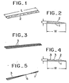
- Figs. 1 to 4 show examples of steel fibers according to the present invention, which are generally flat, and may have a cross section of crescent shape (Fig. 1 and 2) or of mountain and valley (corrugated) shape (Figs. 3 and 4).
- the fibers have a smooth face 1 curved in the direction of width W and a rough face 2 similar to pear skin as shown in Fig. 2, or a face formed with furrows or wrinkles 3 running in the length direction L on the rough face 2, said furrows forming said mountain like configuration shown in Fig. 3.
- Fig. 5 shows another example of the invention which is twisted in the length direction of the fiber.
- Each of the steel fibers mentioned above is produced by cutting a steel block on a surface thereof, such as a continuously cast slab or ingot by means of a rotary cutter having a plurality of cutting edges at least approximately parallel to the length direction of the fibers, the cutting direction being essentially normal to the length direction of the fibers. If the cutting direction were along the axial direction of the fiber, notches would be formed in right angle to the axial direction of the fiber, that is, in the width, and the reinforcing effect would be decreased.
- the steel fiber of the invention depends upon such cutting and is flat in shape satisfying the conditions mentioned below which are regarded as essential to preferred embodiments of the invention.
- a basic condition of the fibers according to the invention is that the entire body is flat.
- the steel fibers should be acicular or needle-shaped as seen in chopped fibers or cut wire fibers.
- Acicular shaped means that the cross section is a circle or a polygon of which each of the sides is of the same length.
- the known cut fibers meet this conception, as the width and thickness of these fibers were equal rather than being flat as the said above fibers.
- the area of the smooth face of such fibers is relatively small and that of the rough parts is relatively large. Accordingly, the fiber resistance when touching each another is increased and the fibers easily twine by increasing of the area of the rough surface and the equal shapes of the width and the thickness of the fibers. Further, being of needle shape, the fiber lacks restoration with respect to bending which decreases the workability owing to forming of fiber balls, and the reinforcing effect.
- the conventional technique has been to make the cross section large or the aspect ratio small, but since the steel fibers are mixed into the concrete on a standard of weight of the fibers, the admixed amount of fibers per unit of concrete is decreased, whereby the adhering strength of the single fiber is decreased so that the reinforcing effect was not as high as expected. If the admixed proportion were increased, the fibers get caught to each other to form fiber balls and do not form an even dispersion because they settle down.
- the present invention specifies that the basic shape of the steel fiber is flat, especially the smooth face 1 (Fig. 2) is a long side in the cross section, and the length L being between 20 to 40 mm. Length less than 20 mm is too short and if the above condition 2) were satisfied, the adhesion and desired reinforcing effect would be reduced, thus the desired tensile strength would not be obtained.
- a length of more than 40 mm makes the adhesion excellent and increases the tensile strength, but would decrease rigidity of the fiber owing to the relation between the width W and the thickness t, and the fibers lack firmness so that they tend to break or bend at packing or mixing, or they make bridgings in a dispenser nozzle, hose and the like at blowing or dispensing.
- the length should be between about 20 to 40 mm.
- the characteristics of the desired strength for the reinforcing steel fibers and the workability could not be satisfactorily harmonized if the fiber were only flat. That is, if the fiber was too flat, it would be weakened when it is agitated in the concrete because hardness is wanted. The fibers then would tend to form fiber balls, and provide insufficient reinforcing effect since their tensile strength is low. Contrarily, if the fibers are not flat enough, there would arise problems with respect to the workability and the reinforcing effect.
- the raw material used was a continuously cast billet or slab of low carbon steel (C: 0.04%, P: 0.005%, S: 0.006%, Si: 0.04%, Mn: 0.30%, the rest being Fe and inavoidable impurities).
- investigations were carried out on the steel fibers D and E by securing their one end, positioning a fulcrum having curvature of 5 mm under the secured portion, effecting a predetermined displacement (angle ⁇ ) and mesuring the residual deformation (angle 9') after releasing.
- 8 45° resulted ⁇ ′ up to 30°.
- the flatness index was more than 9
- the invention calls for a specific range of the flatness index, but only with the flatness index, desired results were not always obtained, since an unlimited number of combinations W and t exist.
- Table 2 shows results of the tests made with these fibers.
- W should be at least around 1,5 mm as an absolute value which relates to the smooth surface. If the-area of the smooth surface were too small, the fluidity (dispersion) would be impaired. When W is 1,5 mm, the area of the smooth surface is around 30 mm 2 if the fiber has the minimum of the specified length, and the contacting resistance of the fibers is made preferable. If W were less than 1,5 mm, the absolute value of t would be reduced due to the flatness index in response thereto, and therefore the rigidity is lowered so that the fiber becomes weak and tends to bending or breaking. The surface area is reduced so that the adhesion to the concrete becomes insufficient and the tensile strength is also insufficient. For avoiding these problems, it is necessary that t should be at least 0,2 mm as is seen from Table 2. Therefore, the lower limit of W is about 1,5 mm and the lower limit of t is about 0,2 mm.
- the maximum value of W should be about 2,5 mm. If W is made large and t is made thick, the tensile strength becomes high, but the weight is increased due to increasing of the cross sectional area, and accordingly the admixed proportion of fibers is to be reduced so that the desired reinforcing effect can not be obtained. If the amount of admixed fibers were increased to improve the reinforcing effect, clods would be formed at supplying into the concrete and the fibers settle down during mixing. Further, the production facilities must be large scaled including the milling cutter, and the tools are expensive because of the required strength, so that the production custs are high.
- M, N, P, Q, R, s have W between 1,5 to 2,5 mm and t between 0.2 to 0.3 mm, and the fibers are smooth in fluidity due to the flat shape balanced in the smooth surface and the rough face.
- the rigidity of these fibers can be increased without changing the cross sectional area, and the spring property is as that of a leaf spring.
- the fibers return to the original shape even if a bending moment acts on them while performing the mixture, and the tensile strength of the fibers is high.
- Steel fibers as shown in Fig. 5 were obtained from a continuously cast slab of low carbon steel of the chemical composition mentioned above.
- the fibers of the same number were mixed into the concrete under the condition of the volume fraction of the steel fibers in the concrete being 1 % and the water cement ratio being 50%, and concrete test pieces of 10 x 10 x 40 cm were made.
- the fine aggregate percentage (sand/total aggregates) was 57%
- the maximum size of the rough aggregates (crushed stones) was 15 mm
- the slump was 8 ⁇ 1 cm.
- Table 3 shows the test results of the bending strength and the fiber property at breaking.
Landscapes
- Engineering & Computer Science (AREA)
- Chemical & Material Sciences (AREA)
- Nanotechnology (AREA)
- Mechanical Engineering (AREA)
- Ceramic Engineering (AREA)
- Structural Engineering (AREA)
- Materials Engineering (AREA)
- Organic Chemistry (AREA)
- Civil Engineering (AREA)
- Inorganic Fibers (AREA)
- Curing Cements, Concrete, And Artificial Stone (AREA)
- Reinforcement Elements For Buildings (AREA)
- Yarns And Mechanical Finishing Of Yarns Or Ropes (AREA)
Abstract
Description
- The present invention relates to steel fibers for reinforcing concrete, and more particularly to improved steel fibers which are produced by directly cutting a steel block.
- It is known to mix short steel fibers into liquid concrete in order to improve the rigidity and the tensile strength of the concrete. Various kinds of steel fibers for reinforcing concrete are known, and typical representatives thereof are:
- 1) wire fibers made by cutting rolled and drawn steel wire to predetermined length;
- 2) sheared fibers made by cutting with a rotary edge a coiled material or slitting a cold rolled steel sheet;
- 3) melt extraction fibers made by rotating a water cooled disc on the surface of molten steel for instantaneously solidifying and splashing the molten steel by centrifugal force;
- 4) cut fibers made by cutting a thick steel plate or block.
- Concrete reinforcing steel fibers, in the following shortly called "steel fibers" or simply "fibers", are required in mass production quantities at economical costs because of the large amounts needed, and must have sufficient strength (tensile strength) and suitable adhesive strength to the concrete. In this regard, the above mentioned 3rd type of steel fibers has the advantage of low production costs because it is produced directly from molten steel but is difficult to implement due to difficulties in controlling the temperature of the molten steel and the surface control, and further has the drawback of poor tensile strength.
- Steel fibers of the 1st and 2nd type are superior in the strength characteristics over fibers of the 3rd type, but are expensive since the raw materials have a high processing degree, and the adhering strength is unsatisfactory because of their smooth circular or rectangular cross section. For avoiding these drawbacks, the fibers are partially made uneven by means of physical working or bent a both ends, but in spite of such measures, satisfactory effects could not be obtained since lubricants used at production of the raw material remains on the fiber surfaces. When such fibers are scattered into the concrete they may cause cracks in the concrete due to the so-called notch effect.
- The production of steel fibers of the 4th type by machining a thick steel plate or block is known from US-A-4298660 and DE-A-2994288. In the known method, a milling cutter having a plurality of cutting edges is positioned on the steel plate or block and is moved relatively in the horizontal direction. A surface of said plate or block is machined by the rotating cutting edges to chop steel fibers of approximate triangular form in cross-section. The fibers may have a mountain-like shape in cross-section, and they may be twisted in their length direction. According to this method, steel fibers of high quality may be economically produced, and since these fibers have a rough surface without notches, the adhering strength is satisfactory. As they are subject to large elastic deformation during production, also their strength is sufficient due to work hardening. Therefore these cut fibers of the 4th type as a whole excel the fibers of the 1st, 2nd and 3rd type.
- In addition to the above mentioned requirements to be fulfilled by the steel fibers, workability or handling properties should be taken into consideration. "Workability" means herein that fluidity of the fibers is smooth at packing, wrapping or dispensing, that the fibers do not form aggregates or lumps, that they are uniformly dispersed when mixed with cement, aggregates and other components in a concrete mixer, and that they are not bent or broken during the mixing process.
- Concerning the workability, the steel fibers of the 1st, 2nd and 3rd tpye get entangled to each other at packing into or taking out from a box, and are particularly prone to form so called fiber balls. For removing such conditions, a troublesome disentangling process is required, or special means as a separator often must be provided for in practice. Further, the mixing load is large due to bad dispersion, so that the mixing time is long, and clogging occurs in the machine or dispensing hose, resulting in loss of time and process for setting or disassembling. Since the dispersion in the concrete is not uniform, the required strength of the final set concrete is not secured.
- The steel fibers of the 4th type are indeed preferred over those of the 1 st, 2nd and 3rd type in respect to the production cost, the quality and other features, but in the actual practice these steel fibers are either satisfactory in respect to the reinforcing strength or in respect to the workability, but not in both. Specifically, if the fibers are too thin or too long, bending or breaking occur and cause aggregates, lumps and other inconveniences so that the reinforcing effect is extremely reduced, or if they are too thick in cross section, the adhesive property is reduced so that the steel fibers precipitate down to the lower part of the concrete.
- The aim of the present invention is to avoid the difficulties mentioned above encountered with the known steel fibers.
- A basic object of the invention is to provide steel fibers for reinforcing concrete, which exhibit the required reinforcing effect and excellent workability.
- Another object of the invention is to provide steel fibers which are smooth in their fluidity without getting entangled to each other, and easy in packing or wrapping, and may be added as bulk or lump without the necessity of a special machine such as a separator. Since the fibers are rapidly dispersed uniformly and exhibit high workability and working efficiency, the load of the mixer is low and, thus, the required power is reduced.
- A further object of the invention is to provide steel fibers which have spring properties. If a bending moment is applied to a fiber during mixing or taking out into a dispenser nozzle or hose, the fiber returns to its original shape and does not form a fiber ball nor clogs the nozzle or hose.
- Another object of the invention is to provide steel fibers which are excellent in respect to their adhesive property due to the balance between smooth surface portions and rough surface portions, thereby to increase the reinforcing effect. The rigidity and fluidity of the steel fibers is increased by controlling the shapes in size, instead of making the aspect ratio small, so that the weight is not unnecessarily increased and a large number of fibers may be mixed into a given unit of concrete, and concrete or mortar products of high strength can be produced at high efficiency.
- For accomplishing the above mentioned objects, studies of the relationship between the shape, size, reinforcing effect and workability have been made. With respect to the present kind of steel fibers, one of the most important characteristics is the tensile strength (i.e., the maximum tension which does not cause rupture of the concrete reinforced by admixed steel fibers). The prior art has paid attention only to the tensile strength when determining the sizes and the shapes of the steel fibers. With respect to the fiber length L, diameter d, and adhering strength of the concrete, the tensile strength of was expressed with the expression of "of=Ud". Ud, i.e., the aspect ratio was regarded as the parameters for determining the fiber sizes.
- However, depending upon the investigations on which this invention is based, it has been proved that the workability and the reinforcing effect could not be matched satisfactorily by variation of the parameters of the aspect ratio and the shape and size thereof.
- As a result, investigations have revealed that the requirements with respect to the reinforcing effect and the workability could both be satisfied by making the basic shape of the cut steel fiber flat, and the most effective measure was to select the degree of flatness within a certain range.
- The present steel fibers are made by cutting such that the following parameters are:
- Length L between 20 mm and 40 mm, flatness index N (width W/thickness t) between 7 and 9, w = 1.5 to 2.5 mm and t = 0.2 to 0.3 mm.
- By this means, the fluidity of the fibers per se is excellent and advantageous at wrapping, packing or taking out smoothly without forming balls. Further, the steel fibers are uniformly dispersed into the liquid concrete. The fibers are given moderate hardness, elasticity and required resiliency. If a strong bending moment acts on a fiber, it easily recovers to its original shape due to the elasticity without being bent or broken or clogging in a dispenser hose, and the present fibers have excellent adhesion to the concrete and do not settle down in the fluid concrete.
- Preferred embodiments of the invention are described with reference to the attached drawing.
-
- Fig. 1 is a perspective view showing one example of a steel fiber according to the invention;
- Fig. 2 is an enlarged cross sectional view of the fiber shown in Fig. 1;
- Fig. 3 is a perspective view showing another example of the invention,
- Fig. 4 is an enlarged cross sectional view of the fiber shown in Fig. 3, and
- Fig. 5 is a perspective view showing a further example of the invention.
- Figs. 1 to 4 show examples of steel fibers according to the present invention, which are generally flat, and may have a cross section of crescent shape (Fig. 1 and 2) or of mountain and valley (corrugated) shape (Figs. 3 and 4). The fibers have a smooth face 1 curved in the direction of width W and a
rough face 2 similar to pear skin as shown in Fig. 2, or a face formed with furrows orwrinkles 3 running in the length direction L on therough face 2, said furrows forming said mountain like configuration shown in Fig. 3. Fig. 5 shows another example of the invention which is twisted in the length direction of the fiber. - Each of the steel fibers mentioned above is produced by cutting a steel block on a surface thereof, such as a continuously cast slab or ingot by means of a rotary cutter having a plurality of cutting edges at least approximately parallel to the length direction of the fibers, the cutting direction being essentially normal to the length direction of the fibers. If the cutting direction were along the axial direction of the fiber, notches would be formed in right angle to the axial direction of the fiber, that is, in the width, and the reinforcing effect would be decreased.
- The steel fiber of the invention depends upon such cutting and is flat in shape satisfying the conditions mentioned below which are regarded as essential to preferred embodiments of the invention.
- 1) L = 20 to 40 mm
- 2) N = W/t = 7 to 9,
- herein W = 1,5 to 2,5 mm and t = 0,2 to 0,3 mm,
- wherein
- L is the length of the fiber,
- W is the width,
- t is the thickness (the maximum thickness) and
- N = W/t is the flatness index.
- A basic condition of the fibers according to the invention is that the entire body is flat. Generally, it has been considered previously that the steel fibers should be acicular or needle-shaped as seen in chopped fibers or cut wire fibers. Acicular shaped means that the cross section is a circle or a polygon of which each of the sides is of the same length. The known cut fibers meet this conception, as the width and thickness of these fibers were equal rather than being flat as the said above fibers.
- However, it has been found that the area of the smooth face of such fibers is relatively small and that of the rough parts is relatively large. Accordingly, the fiber resistance when touching each another is increased and the fibers easily twine by increasing of the area of the rough surface and the equal shapes of the width and the thickness of the fibers. Further, being of needle shape, the fiber lacks restoration with respect to bending which decreases the workability owing to forming of fiber balls, and the reinforcing effect. In order to improve these matters the conventional technique has been to make the cross section large or the aspect ratio small, but since the steel fibers are mixed into the concrete on a standard of weight of the fibers, the admixed amount of fibers per unit of concrete is decreased, whereby the adhering strength of the single fiber is decreased so that the reinforcing effect was not as high as expected. If the admixed proportion were increased, the fibers get caught to each other to form fiber balls and do not form an even dispersion because they settle down.
- In view of such practices, the present invention specifies that the basic shape of the steel fiber is flat, especially the smooth face 1 (Fig. 2) is a long side in the cross section, and the length L being between 20 to 40 mm. Length less than 20 mm is too short and if the above condition 2) were satisfied, the adhesion and desired reinforcing effect would be reduced, thus the desired tensile strength would not be obtained. A length of more than 40 mm makes the adhesion excellent and increases the tensile strength, but would decrease rigidity of the fiber owing to the relation between the width W and the thickness t, and the fibers lack firmness so that they tend to break or bend at packing or mixing, or they make bridgings in a dispenser nozzle, hose and the like at blowing or dispensing.
- Thus the length should be between about 20 to 40 mm. However, the characteristics of the desired strength for the reinforcing steel fibers and the workability could not be satisfactorily harmonized if the fiber were only flat. That is, if the fiber was too flat, it would be weakened when it is agitated in the concrete because hardness is wanted. The fibers then would tend to form fiber balls, and provide insufficient reinforcing effect since their tensile strength is low. Contrarily, if the fibers are not flat enough, there would arise problems with respect to the workability and the reinforcing effect.
- Experiments have been carried out for establishing the proper range of the flatness index. The raw material used was a continuously cast billet or slab of low carbon steel (C: 0.04%, P: 0.005%, S: 0.006%, Si: 0.04%, Mn: 0.30%, the rest being Fe and inavoidable impurities). This slab was machined with a plane milling cutter having cemented carbide chips to produce flat steel fibers whose basic shapes were as shown in Fig. 3 having L = 30 mm, W = 2 mm and t being of eight types (A-H).

- With respect to "scattering" in Table 1, about 200 pieces of the steel fibers each type were at random filled in a box, the box was opened under windless condition at height of 1 m from the ground, and then the spreading and dispersion were measured. For mixing into the concrete, fibers of the same number were mixed under the constant rotation of a ball like mixer. The volume fraction of the steel fibers in the concrete was 1 %, and the water/cement ratio was 50%.
- As apparent from Table 1, when the flatness index is too large, that is, the thickness is too small, the tensile strength was decreased and the dispersion is not suitable because fiber balls easily form. When the flatness index is small (large thickness), the tensile strength is sufficient but the scattering is not suitable. On the other hand, fibers having a flatness index from 7 to 9, i.e., D, E, F, are excellent with respect to strength and scattering. After addition to the concrete, those fibers are instantly dispersed three- dimensionally and mixed with the aggregates and the cement rapidly without bending or breaking and forming fiber balls. Thus, it is seen that the flatness index is an important factor for the reinforcing steel fibers.
- The flatness index has a strong effect on the spring property and the most suitable range is N = 7 to 9. In order to establish this effect, investigations were carried out on the steel fibers D and E by securing their one end, positioning a fulcrum having curvature of 5 mm under the secured portion, effecting a predetermined displacement (angle θ) and mesuring the residual deformation (angle 9') after releasing. 9 = 10 to 30° resulted θ = 0°, 8 = 45° resulted θ′ up to 30°. On the other hand, if the flatness index was more than 9, the residual deformation was large as θ = 10 to 30° resulted θ′ = around 20°. Conversely, if the flatness index was less than 7 and when 8 was small, θ′ was also small, and when θ was large, the residual deformation increased rapidly, and the resilience ceased. In the known fiber products (cross section 0.75 mm x 0.75 mm) θ = 10° resulted in θ′ = 3°, 9 = 30° in θ′ = 25°, 8 = 60° in θ′ = 55°, and 9 = 90° resulted in θ′ = 85°.
- For the reason of the above circumstances, the invention calls for a specific range of the flatness index, but only with the flatness index, desired results were not always obtained, since an unlimited number of combinations W and t exist. In the course of further investigations, flat steel fibers having various values of W and t have been made, which meet the condition L = 30 mm and the flatness index 7 to 9.
- Table 2 shows results of the tests made with these fibers.


- It can be seen from Table 2 that W should be at least around 1,5 mm as an absolute value which relates to the smooth surface. If the-area of the smooth surface were too small, the fluidity (dispersion) would be impaired. When W is 1,5 mm, the area of the smooth surface is around 30 mm2 if the fiber has the minimum of the specified length, and the contacting resistance of the fibers is made preferable. If W were less than 1,5 mm, the absolute value of t would be reduced due to the flatness index in response thereto, and therefore the rigidity is lowered so that the fiber becomes weak and tends to bending or breaking. The surface area is reduced so that the adhesion to the concrete becomes insufficient and the tensile strength is also insufficient. For avoiding these problems, it is necessary that t should be at least 0,2 mm as is seen from Table 2. Therefore, the lower limit of W is about 1,5 mm and the lower limit of t is about 0,2 mm.
- It can be seen from Table 2 that the maximum value of W should be about 2,5 mm. If W is made large and t is made thick, the tensile strength becomes high, but the weight is increased due to increasing of the cross sectional area, and accordingly the admixed proportion of fibers is to be reduced so that the desired reinforcing effect can not be obtained. If the amount of admixed fibers were increased to improve the reinforcing effect, clods would be formed at supplying into the concrete and the fibers settle down during mixing. Further, the production facilities must be large scaled including the milling cutter, and the tools are expensive because of the required strength, so that the production custs are high.
- M, N, P, Q, R, s have W between 1,5 to 2,5 mm and t between 0.2 to 0.3 mm, and the fibers are smooth in fluidity due to the flat shape balanced in the smooth surface and the rough face. The rigidity of these fibers can be increased without changing the cross sectional area, and the spring property is as that of a leaf spring. Thus, the fibers return to the original shape even if a bending moment acts on them while performing the mixture, and the tensile strength of the fibers is high.
- Steel fibers as shown in Fig. 5 were obtained from a continuously cast slab of low carbon steel of the chemical composition mentioned above. The fibers of the same number were mixed into the concrete under the condition of the volume fraction of the steel fibers in the concrete being 1 % and the water cement ratio being 50%, and concrete test pieces of 10 x 10 x 40 cm were made. The fine aggregate percentage (sand/total aggregates) was 57%, the maximum size of the rough aggregates (crushed stones) was 15 mm, and the slump was 8 ± 1 cm. Table 3 shows the test results of the bending strength and the fiber property at breaking.

- In Table 3, I shows the effect of the length L, II shows the effect of W/t, III shows the effect of W, and IV shows the effect of t, respectively. If the length L were not proper, the balance of the strength and the workability would be inferior though the other conditions are satisfied. Similarly, if W/t, W and t were outside of the ranges taught by the invention, both of the mentioned desired properties would be impaired. Being within the scope of the invention, said two would be superior.
Claims (4)
wherein L is the length of the fiber, W is the width of the fiber, t is the thickness of the fiber, and N is the flatness index.
Priority Applications (1)
| Application Number | Priority Date | Filing Date | Title |
|---|---|---|---|
| AT82107124T ATE16274T1 (en) | 1982-03-03 | 1982-08-06 | STEEL FIBERS FOR REINFORCEMENT OF CONCRETE. |
Applications Claiming Priority (2)
| Application Number | Priority Date | Filing Date | Title |
|---|---|---|---|
| JP57033228A JPS58151362A (en) | 1982-03-03 | 1982-03-03 | Steel fiber for concrete reinforcement |
| JP33228/82 | 1982-03-03 |
Publications (2)
| Publication Number | Publication Date |
|---|---|
| EP0087496A1 EP0087496A1 (en) | 1983-09-07 |
| EP0087496B1 true EP0087496B1 (en) | 1985-10-30 |
Family
ID=12380595
Family Applications (1)
| Application Number | Title | Priority Date | Filing Date |
|---|---|---|---|
| EP82107124A Expired EP0087496B1 (en) | 1982-03-03 | 1982-08-06 | Steel fibers for reinforcing concrete |
Country Status (6)
| Country | Link |
|---|---|
| EP (1) | EP0087496B1 (en) |
| JP (1) | JPS58151362A (en) |
| AT (1) | ATE16274T1 (en) |
| DD (1) | DD208385A5 (en) |
| DE (1) | DE3267172D1 (en) |
| SU (1) | SU1333241A3 (en) |
Families Citing this family (6)
| Publication number | Priority date | Publication date | Assignee | Title |
|---|---|---|---|---|
| JPS60231449A (en) * | 1984-04-26 | 1985-11-18 | 野口 煕 | Construction structure comprising fibrous metal-mixed concrete |
| DE4208080A1 (en) * | 1992-03-13 | 1993-09-16 | Vulkan Harex Stahlfasertech | METHOD AND CUTTING TOOL FOR PRODUCING STEEL SHEET FIBERS |
| DE19531826C2 (en) * | 1995-08-15 | 1999-03-18 | Mannesmann Ag | Process for the production of steel fibers |
| NL1016105C2 (en) * | 2000-09-05 | 2002-03-07 | Harex Nederland B V | Fiber mixture for concrete. |
| DE102004038331A1 (en) | 2004-08-06 | 2006-03-16 | Emitec Gesellschaft Für Emissionstechnologie Mbh | Metallic fibers, their production and applications |
| US10357897B2 (en) * | 2015-04-01 | 2019-07-23 | Sumitomo Electric Industries, Ltd. | Concrete-reinforcing shaped body, method of manufacturing the same, structure of packaging concrete-reinforcing shaped body, and method of mixing fiber-reinforced concrete |
Family Cites Families (6)
| Publication number | Priority date | Publication date | Assignee | Title |
|---|---|---|---|---|
| AR206305A1 (en) * | 1972-11-28 | 1976-07-15 | Australian Wire Ind Pty | REINFORCEMENT FIBERS FOR MOLDABLE MATRIX MATERIALS METHOD AND APPARATUS TO PRODUCE IT |
| SE7414809L (en) * | 1974-11-26 | 1976-05-28 | Skf Nova Ab | CONCRETE REQUIREMENTS AND METHODS OF MANUFACTURE |
| JPS52144424A (en) * | 1976-05-24 | 1977-12-01 | Takeo Nakagawa | Manufacture of steel fiber for reinforcing concrete |
| JPS5366753A (en) * | 1976-11-26 | 1978-06-14 | Ngk Spark Plug Co | Pickup transmitter |
| JPS54112517A (en) * | 1978-02-22 | 1979-09-03 | Aida Eng Ltd | Steel fiber for reinforcing concrete and its preparation |
| JPS55170623U (en) * | 1979-05-24 | 1980-12-08 |
-
1982
- 1982-03-03 JP JP57033228A patent/JPS58151362A/en active Granted
- 1982-08-06 DE DE8282107124T patent/DE3267172D1/en not_active Expired
- 1982-08-06 AT AT82107124T patent/ATE16274T1/en not_active IP Right Cessation
- 1982-08-06 EP EP82107124A patent/EP0087496B1/en not_active Expired
-
1983
- 1983-01-28 DD DD83247552A patent/DD208385A5/en not_active IP Right Cessation
- 1983-03-02 SU SU833560647A patent/SU1333241A3/en active
Also Published As
| Publication number | Publication date |
|---|---|
| DD208385A5 (en) | 1984-05-02 |
| ATE16274T1 (en) | 1985-11-15 |
| JPS58151362A (en) | 1983-09-08 |
| EP0087496A1 (en) | 1983-09-07 |
| JPH0218303B2 (en) | 1990-04-25 |
| DE3267172D1 (en) | 1985-12-05 |
| SU1333241A3 (en) | 1987-08-23 |
Similar Documents
| Publication | Publication Date | Title |
|---|---|---|
| US4027718A (en) | Process for manufacturing a reinforcing material for concrete | |
| EP0032421B2 (en) | Fiber-reinforced concrete | |
| US4559276A (en) | Concrete reinforcing steel fibers | |
| US4560622A (en) | Steel fiber for reinforcing concrete and production thereof | |
| DE69219425T2 (en) | Cutting insert | |
| US4298660A (en) | Steel fiber for reinforced concrete | |
| DE68919908T2 (en) | Grinding wheel with high impact resistance for in-situ grinding of rolls. | |
| EP0475917B1 (en) | A metal fibre for reinforcing concrete | |
| Ananthan et al. | Macroscopic aspects of Lüders band deformation in mild steel | |
| EP0087496A1 (en) | Steel fibers for reinforcing concrete | |
| DE112005003549B4 (en) | Process for producing silicon blocks and silicon wafers | |
| SE407950B (en) | FIBER REFINING ELEMENT | |
| US2244052A (en) | Method of forming hard cemented carbide products | |
| WO2004052605A2 (en) | Frame saw for cutting granite and method to improve performance of frame saw for cutting granite | |
| DE69017374T2 (en) | Drawn steel staple fiber and fiber composite material containing this fiber. | |
| JP6458194B1 (en) | Room temperature asphalt mixture | |
| DE8227342U1 (en) | Stone working tool | |
| KR19980069733A (en) | Machining centers and processing parts | |
| EP1282751A1 (en) | Steel fibers | |
| AT336818B (en) | MACHINE COMPONENTS DEMANDED FOR WEAR | |
| OKUsHIMA et al. | Machinability of Metals: Chip Formation of Leaded Steels | |
| AT56370B (en) | Grinding mill. | |
| JP3190178B2 (en) | Steel fiber for concrete reinforcement | |
| JPH04365835A (en) | Production of free cutting steel containing boron nitride | |
| JPS6138893Y2 (en) |
Legal Events
| Date | Code | Title | Description |
|---|---|---|---|
| PUAI | Public reference made under article 153(3) epc to a published international application that has entered the european phase |
Free format text: ORIGINAL CODE: 0009012 |
|
| AK | Designated contracting states |
Designated state(s): AT BE CH DE FR GB IT LI LU NL SE |
|
| 17P | Request for examination filed |
Effective date: 19830914 |
|
| ITF | It: translation for a ep patent filed | ||
| GRAA | (expected) grant |
Free format text: ORIGINAL CODE: 0009210 |
|
| AK | Designated contracting states |
Designated state(s): AT BE CH DE FR GB IT LI LU NL SE |
|
| REF | Corresponds to: |
Ref document number: 16274 Country of ref document: AT Date of ref document: 19851115 Kind code of ref document: T |
|
| REF | Corresponds to: |
Ref document number: 3267172 Country of ref document: DE Date of ref document: 19851205 |
|
| ET | Fr: translation filed | ||
| PLBE | No opposition filed within time limit |
Free format text: ORIGINAL CODE: 0009261 |
|
| STAA | Information on the status of an ep patent application or granted ep patent |
Free format text: STATUS: NO OPPOSITION FILED WITHIN TIME LIMIT |
|
| 26N | No opposition filed | ||
| ITTA | It: last paid annual fee | ||
| EPTA | Lu: last paid annual fee | ||
| EAL | Se: european patent in force in sweden |
Ref document number: 82107124.8 |
|
| PGFP | Annual fee paid to national office [announced via postgrant information from national office to epo] |
Ref country code: DE Payment date: 20010730 Year of fee payment: 20 |
|
| PGFP | Annual fee paid to national office [announced via postgrant information from national office to epo] |
Ref country code: GB Payment date: 20010801 Year of fee payment: 20 |
|
| PGFP | Annual fee paid to national office [announced via postgrant information from national office to epo] |
Ref country code: SE Payment date: 20010807 Year of fee payment: 20 |
|
| PGFP | Annual fee paid to national office [announced via postgrant information from national office to epo] |
Ref country code: LU Payment date: 20010808 Year of fee payment: 20 |
|
| PGFP | Annual fee paid to national office [announced via postgrant information from national office to epo] |
Ref country code: FR Payment date: 20010810 Year of fee payment: 20 |
|
| PGFP | Annual fee paid to national office [announced via postgrant information from national office to epo] |
Ref country code: AT Payment date: 20010813 Year of fee payment: 20 |
|
| PGFP | Annual fee paid to national office [announced via postgrant information from national office to epo] |
Ref country code: CH Payment date: 20010815 Year of fee payment: 20 |
|
| PGFP | Annual fee paid to national office [announced via postgrant information from national office to epo] |
Ref country code: NL Payment date: 20010830 Year of fee payment: 20 |
|
| PGFP | Annual fee paid to national office [announced via postgrant information from national office to epo] |
Ref country code: BE Payment date: 20010927 Year of fee payment: 20 |
|
| BE20 | Be: patent expired |
Free format text: 20020806 *AIDA ENGINEERING LTD |
|
| REG | Reference to a national code |
Ref country code: GB Ref legal event code: IF02 |
|
| PG25 | Lapsed in a contracting state [announced via postgrant information from national office to epo] |
Ref country code: LI Free format text: LAPSE BECAUSE OF EXPIRATION OF PROTECTION Effective date: 20020805 Ref country code: GB Free format text: LAPSE BECAUSE OF EXPIRATION OF PROTECTION Effective date: 20020805 Ref country code: CH Free format text: LAPSE BECAUSE OF EXPIRATION OF PROTECTION Effective date: 20020805 |
|
| PG25 | Lapsed in a contracting state [announced via postgrant information from national office to epo] |
Ref country code: NL Free format text: LAPSE BECAUSE OF EXPIRATION OF PROTECTION Effective date: 20020806 Ref country code: LU Free format text: LAPSE BECAUSE OF EXPIRATION OF PROTECTION Effective date: 20020806 Ref country code: AT Free format text: LAPSE BECAUSE OF EXPIRATION OF PROTECTION Effective date: 20020806 |
|
| REG | Reference to a national code |
Ref country code: GB Ref legal event code: PE20 Effective date: 20020805 |
|
| REG | Reference to a national code |
Ref country code: CH Ref legal event code: PL |
|
| EUG | Se: european patent has lapsed |
Ref document number: 82107124.8 |
|
| NLV7 | Nl: ceased due to reaching the maximum lifetime of a patent |
Effective date: 20020806 |