EP0087254B1 - Fluid actuator with sequence-power valve - Google Patents
Fluid actuator with sequence-power valve Download PDFInfo
- Publication number
- EP0087254B1 EP0087254B1 EP83300721A EP83300721A EP0087254B1 EP 0087254 B1 EP0087254 B1 EP 0087254B1 EP 83300721 A EP83300721 A EP 83300721A EP 83300721 A EP83300721 A EP 83300721A EP 0087254 B1 EP0087254 B1 EP 0087254B1
- Authority
- EP
- European Patent Office
- Prior art keywords
- lock
- piston
- actuator
- fluid pressure
- fluid
- Prior art date
- Legal status (The legal status is an assumption and is not a legal conclusion. Google has not performed a legal analysis and makes no representation as to the accuracy of the status listed.)
- Expired
Links
- 239000012530 fluid Substances 0.000 title claims description 61
- 238000013459 approach Methods 0.000 claims description 2
- 238000003780 insertion Methods 0.000 claims 2
- 230000037431 insertion Effects 0.000 claims 2
- 230000001360 synchronised effect Effects 0.000 description 2
- 230000000903 blocking effect Effects 0.000 description 1
- 230000007423 decrease Effects 0.000 description 1
- 230000000694 effects Effects 0.000 description 1
- 230000013011 mating Effects 0.000 description 1
- 230000000717 retained effect Effects 0.000 description 1
Images
Classifications
-
- F—MECHANICAL ENGINEERING; LIGHTING; HEATING; WEAPONS; BLASTING
- F15—FLUID-PRESSURE ACTUATORS; HYDRAULICS OR PNEUMATICS IN GENERAL
- F15B—SYSTEMS ACTING BY MEANS OF FLUIDS IN GENERAL; FLUID-PRESSURE ACTUATORS, e.g. SERVOMOTORS; DETAILS OF FLUID-PRESSURE SYSTEMS, NOT OTHERWISE PROVIDED FOR
- F15B15/00—Fluid-actuated devices for displacing a member from one position to another; Gearing associated therewith
- F15B15/20—Other details, e.g. assembly with regulating devices
- F15B15/28—Means for indicating the position, e.g. end of stroke
- F15B15/2815—Position sensing, i.e. means for continuous measurement of position, e.g. LVDT
- F15B15/2823—Position sensing, i.e. means for continuous measurement of position, e.g. LVDT by a screw mechanism attached to the piston
-
- F—MECHANICAL ENGINEERING; LIGHTING; HEATING; WEAPONS; BLASTING
- F02—COMBUSTION ENGINES; HOT-GAS OR COMBUSTION-PRODUCT ENGINE PLANTS
- F02K—JET-PROPULSION PLANTS
- F02K1/00—Plants characterised by the form or arrangement of the jet pipe or nozzle; Jet pipes or nozzles peculiar thereto
- F02K1/54—Nozzles having means for reversing jet thrust
- F02K1/76—Control or regulation of thrust reversers
-
- F—MECHANICAL ENGINEERING; LIGHTING; HEATING; WEAPONS; BLASTING
- F15—FLUID-PRESSURE ACTUATORS; HYDRAULICS OR PNEUMATICS IN GENERAL
- F15B—SYSTEMS ACTING BY MEANS OF FLUIDS IN GENERAL; FLUID-PRESSURE ACTUATORS, e.g. SERVOMOTORS; DETAILS OF FLUID-PRESSURE SYSTEMS, NOT OTHERWISE PROVIDED FOR
- F15B15/00—Fluid-actuated devices for displacing a member from one position to another; Gearing associated therewith
- F15B15/20—Other details, e.g. assembly with regulating devices
- F15B15/26—Locking mechanisms
- F15B15/261—Locking mechanisms using positive interengagement, e.g. balls and grooves, for locking in the end positions
-
- F—MECHANICAL ENGINEERING; LIGHTING; HEATING; WEAPONS; BLASTING
- F15—FLUID-PRESSURE ACTUATORS; HYDRAULICS OR PNEUMATICS IN GENERAL
- F15B—SYSTEMS ACTING BY MEANS OF FLUIDS IN GENERAL; FLUID-PRESSURE ACTUATORS, e.g. SERVOMOTORS; DETAILS OF FLUID-PRESSURE SYSTEMS, NOT OTHERWISE PROVIDED FOR
- F15B15/00—Fluid-actuated devices for displacing a member from one position to another; Gearing associated therewith
- F15B15/08—Characterised by the construction of the motor unit
- F15B15/14—Characterised by the construction of the motor unit of the straight-cylinder type
- F15B2015/1495—Characterised by the construction of the motor unit of the straight-cylinder type with screw mechanism attached to the piston
Definitions
- This invention relates generally as indicated to a fluid actuator with sequence-power valve for releasing a lock mechanism that locks the actuator against movement in one position, and then ports the fluid pressure directly to the actuator to effect the desired movement thereof.
- the sequence-power valve includes a lock piston which when acted upon by fluid pressure moves a lock release lever to release the lock mechanism. Also, a lost-motion connection is provided between the lock release lever and lock piston which permits the lock release lever to remain in the lock releasing position during return movement of the lock piston when the fluid pressure acting on the lock piston is reduced.
- US-A-2 349 244 It is generally known from US-A-2 349 244 to provide a single valve mechanism which is used first to release the actuator lock mechanism and then to port fluid pressure to the fluid actuator for actuating same following release of the lock.
- the fluid actuator shown in US-A-2 349 244 comprises a cylinder containing a piston-rod assembly that is extendible under pressure, together with releasable lock means for preventing the piston-rod assembly from extending, and lock release means for releasing the lock means.
- the lock release means includes a fluid pressure operated lock. piston movable in a direction to release the lock means, and a lock release lever for transmitting a lock release force from the lock piston to the lock means during movement of the lock piston in a direction to release the lock means.
- the fluid actuator includes passage means which are unblocked by the lock piston during movement in a direction to release the lock means for porting the fluid pressure directly to the actuator to cause the piston-rod assembly to extend upon release of the lock means.
- passage means which are unblocked by the lock piston during movement in a direction to release the lock means for porting the fluid pressure directly to the actuator to cause the piston-rod assembly to extend upon release of the lock means.
- a fluid actuator comprising a cylinder containing a piston-rod assembly that is extendible under pressure, releasable lock means for preventing said piston-rod assembly from extending, and lock release means for releasing said lock means, said lock release means including a fluid pressure operated lock piston movable in a direction to release said lock means, a lock release lever.
- a lock disengaging force is continuously applied to the lock mechanism to maintain the lock mechanism unlocked except when the actuator nears the position at which locking takes place.
- valve mechanism is maintained substantially fully open for maximum flow to the actuator during the application of operating pressure thereto despite fluctuations in such operating pressure.
- a restrictor in the flow path from the valve mechanism to the actuator assists in maintaining the'valve piston in a position in which such flow path is substantially fully open for substantially full flow to the actuator during operation thereof despite fluctuations in such fluid pressure.
- a torsion spring acting on the lever will cause the lock mechanism to remain unlocked until the actuator nears such one position, at which time a lock spring interposed between the movable lock part and actuator piston is compressed sufficiently to overcome the force of the torsion spring and re-engage the lock.
- the lost-motion connection between the valve piston and lever permits return movement of the valve piston without affecting the position of the lever.
- a fluid actuator 1 including a cylinder 2 containing a piston 3 axially movable therewithin. Attached to the piston is a hollow rod 4 which extends through the rod end 5 of the cylinder and has a rod end assembly 6 on its outboard end to facilitate connection to the movable or stationary part of the device to be actuated, for example, the thrust reversers for a jet engine on an aircraft.
- a suitable trunnion mount 8 may also be provided on the cylinder to facilitate connection to the other part of the device to be actuated.
- the piston 3 has a high lead Acme nut 9 in the center thereof which is coupled to a mating Acme screw shaft 10.
- One end of the screw shaft may be journaled in suitable bearings 11 within an actuator housing 12 attached to the head end of the cylinder.
- the other end of the screw shaft extends into the hollow piston rod 4 a substantial distance beyond the nut.
- the screw shaft 10 has a high lead worm wheel 15 attached thereto which mates with a worm shaft 16 mounted for rotation within a transverse bore 17 in the actuator housing. Since the speed of the worm shaft is also proportional to the velocity of the piston rod, when the worm shafts of two or more actuators are connected together by a synchronous drive shaft or the like, they will be mechanically synchronized in both position and motion, as well known in the art.
- a lock mechanism 18 which may include a movable lock sleeve 19 axially movable within the actuator housing toward and away from the adjacent end of the worm gear 15.
- the lock sleeve 19 has a central opening 20 through which the screw shaft 10 extends, with sufficient clearance therebetween to permit rotation of the screw shaft relative to the lock sleeve.
- a splined connection 21 is provided between the movable lock sleeve and a piston stop 22 within the actuator housing.
- the adjacent end faces of the worm gear 15 and movable lock sleeve 19 have cooperating lock teeth 23 thereon with ramp angles which when engaged permit ratcheting of the worm gear relative to the movable lock sleeve during retraction of the piston but not during extension thereof. Accordingly, the piston will continue to retract until it engages the retract stop 22. However, if at any time during such ratcheting an attempt is made to reverse the piston direction, the lock teeth will instantly engage thus locking the screw shaft 10 against rotation and preventing the piston from extending.
- the movable lock sleeve 19 When the piston 2 is fully retracted, the movable lock sleeve 19 is normally maintained in engagement with the worm gear 15 by a lock spring 26 interposed between the movable lock sleeve and piston head 28.
- a lock spring 26 interposed between the movable lock sleeve and piston head 28.
- the piston head compresses the lock spring, causing the teeth on the movable lock sleeve to move into engagement with the teeth on the worm gear.
- sequence-power valve 30 the details of which will be described hereafter.
- sequence-power valve may be contained in a separate housing 31 having a generally right angle extension 32 at one end adapted to be received in a valve port 33 in one side of the actuator housing 12 and releasably retained in place as by bolts 34 or the like (see Fig. 4).
- the extension contains a transverse bore 35 in which a toggle type lock release lever 36 is mounted on a shaft 37 for limited pivotal movement.
- the inner end of the lock release lever extends into the actuator housing and has a fork 38 thereon surrounding the movable lock sleeve 19.
- the fork 38 will engage a shoulder 40 on the movable lock sleeve thus forcing the movable lock sleeve out of engagement with the worm gear 15 as shown in Fig. 5.
- a movable lock plunger 45 is provided in a longitudinal bore 46 in the sequence-power valve housing 31 extending in a direction generally parallel to the longitudinal axis of the actuator cylinder.
- the lock plunger has a longitudinal slot 47 therein which receives the outer end 48 of the lock release lever 36.
- a lock piston 50 Also contained in the longitudinal bore 46 adjacent one end of the lock plunger 45 is a lock piston 50.
- the lock piston has a stem 51 on the inner end thereof which is received in a longitudinal slot 52 in the outer end of the lock plunger.
- a flange or shoulder 53 At the innermost end of the stem is a flange or shoulder 53 which is received in a transverse slot 54 in the lock plunger intersecting the inner end of the longitudinal slot 52.
- Both such slots 52, 54 extend into the lock plunger 45 from the same side as shown in Fig. 2 to permit the stem and flange to be inserted therein before the Icok plunger and piston are inserted into the longitudinal bore 46.
- Such a connection between the lock plunger 45 and piston 50 will take care of any slight axial misalignment that may exist between these two parts, thus eliminating the need for having to make them perfectly concentric.
- the lock piston 50 has a differential area 58 which is acted upon by fluid pressure admitted to a lock-in annulus 59 within the bore 46 through an exterior port 60 (see Fig. 4) to cause the lock piston 50 to move to the left as viewed in Figs. 1 and 5, dragging the lock plunger 45 with it.
- This causes the lock release lever 36 to pivot about the shaft 37 and move the lock sleeve 19 axially inwardly against the force of the lock spring 26 to disengage the lock sleeve from the worm gear as shown in Fig. 5.
- system pressure Before system pressure is admitted to the lock-in annulus 59 for effecting release of the lock, such system pressure is desirably applied to the retract side 62 of the actuator through a retract port 63 and porting tube 64 to remove any axial tension loads on the actuator which might otherwise interface with release of the lock. Then, with system pressure still applied to the retract port, system pressure is also applied to the lock-in annulus 59 to release the lock in the manner previously described.
- the system pressure acting on the lock piston is ported to the extend side 29 of the actuator through another annulus 65 in the lock piston bore 46 which is uncovered by the lock piston following such movement as shown in Fig. 5.
- This annulus communicates with the extend side of the actuator through a passageway 66 in the sequence-power valve housing 31 which is connected to the outer end of the transverse bore 35 in such housing.
- the fluid entering such transverse bore flows around the lock plunger 45 and lock release lever 36 and into the extend side of the actuator through the valve port 33 in the actuator housing 12. Since the area of the piston 3 exposed to the extend pressure is greater than that exposed to the retract pressure, the actuator will extend. As it does so, the piston moves away from the lock spring 26, thus causing the lock spring to be fully extended, at which point it is no longer effective in applying a locking force to the movable lock sleeve 19.
- a return spring 70 acting on the outer end of the lock piston 50 may start to return the lock piston and plunger 45 to their original position.
- a torsion spring 71 acting on the lock release lever 36 will still maintain the movable lock sleeve 19 out of engagement with the worm wheel 15 so that the actuator does not suddenly stop. Any such return movement of the lock piston and plunger will not affect the position of the lock release lever because of the length of the slot 47 in the lock plunger which accommodates such movement. However, such return movement of the lock piston could cut down the flow of fluid through the annulus 65 to the extend side of the actuator.
- a restrictor 72 may be provided in the passageway 66 communicating with the annulus 65 to help maintain the pressure on the lock piston high enough such that it will not cycle during extension of the actuator.
- the pressure acting on the extend side of the actuator is reduced, as by connecting the port 60 and thus the lock-in annulus 59 in communication therewith to return pressure, while still maintaining system pressure on the retract side of the actuator.
- the return spring 70 acting on the lock piston 50 will cause the lock piston to return to its original position blocking fluid flow from the extend side of the actuator through the lock valve 50.
- return flow from the extend side of the actuator still occurs through a check valve 75 in another passage 76 in the valve housing 31 providing communication between the annulus 65 and annulus 59 through such check valve as shown in Fig. 4.
- the lock is prevented from prematurely engaging by the torsion spring 71 which maintains the lock release lever 36 in the unlocking position shown in Fig. 5 until the piston 3 engages the lock spring 26 and compresses same sufficiently to overcome the relatively light force of the torsion spring and force the lock teeth 23 into engagement. This normally occurs within the last 0.8 cm (3/10 inch) or so of the retract stroke.
- the actuator will continue to move in the stow direction until the actuator piston engages the internal stop 22 because of the torque developed by the screw shaft 10 and the ramp angles of the lock teeth 23 which cause the lock teeth to ratchet over each other.
- the screw shaft also stops, and since the lock teeth are already in engagement with each other, any motion that tends to extend the actuator will cause the locking faces of the lock teeth to engage thus providing a positive lock against such motion.
- the sequence-power valve of the present invention not only releases the lock mechanism for the actuator when fluid pressure is applied thereto, but such valve also ports such fluid pressure directly to the actuator to cause same to move in the desired direction following release of the lock. Accordingly, the need for a separate valve member and the associated external tubing for interconnecting the parts to supply fluid pressure to the actuator after the actuator has been unlocked is eliminated. Provision is also made for maintaining the valve mechanism substantially fully open for maximum flow to the actuator during actuation thereof despite fluctuations in such fluid pressure. Moreover, once the lock mechanism is disengaged, such disengagement is assured until such time as the actuator is returned to the original position at which reengagement of the lock occurs.
Landscapes
- Engineering & Computer Science (AREA)
- Mechanical Engineering (AREA)
- General Engineering & Computer Science (AREA)
- Physics & Mathematics (AREA)
- Fluid Mechanics (AREA)
- Chemical & Material Sciences (AREA)
- Combustion & Propulsion (AREA)
- Actuator (AREA)
Description
- This invention relates generally as indicated to a fluid actuator with sequence-power valve for releasing a lock mechanism that locks the actuator against movement in one position, and then ports the fluid pressure directly to the actuator to effect the desired movement thereof. The sequence-power valve includes a lock piston which when acted upon by fluid pressure moves a lock release lever to release the lock mechanism. Also, a lost-motion connection is provided between the lock release lever and lock piston which permits the lock release lever to remain in the lock releasing position during return movement of the lock piston when the fluid pressure acting on the lock piston is reduced.
- It is generally known from US-A-2 349 244 to provide a single valve mechanism which is used first to release the actuator lock mechanism and then to port fluid pressure to the fluid actuator for actuating same following release of the lock. The fluid actuator shown in US-A-2 349 244 comprises a cylinder containing a piston-rod assembly that is extendible under pressure, together with releasable lock means for preventing the piston-rod assembly from extending, and lock release means for releasing the lock means. The lock release means includes a fluid pressure operated lock. piston movable in a direction to release the lock means, and a lock release lever for transmitting a lock release force from the lock piston to the lock means during movement of the lock piston in a direction to release the lock means. Also, the fluid actuator includes passage means which are unblocked by the lock piston during movement in a direction to release the lock means for porting the fluid pressure directly to the actuator to cause the piston-rod assembly to extend upon release of the lock means. However, there is no provision in US-A-2 349 244 for permitting the lock release lever to remain in the lock releasing position during return movement of the lock piston when the fluid pressure acting on the lock piston is reduced.
- According to the present invention there is provided a fluid actuator comprising a cylinder containing a piston-rod assembly that is extendible under pressure, releasable lock means for preventing said piston-rod assembly from extending, and lock release means for releasing said lock means, said lock release means including a fluid pressure operated lock piston movable in a direction to release said lock means, a lock release lever. mounted for pivotal movement for transmitting a lock release force from said lock piston to said lock means during movement of said lock piston in a direction to release said lock means, passage means which are unblocked by said lock piston during movement in a direction to release said lock means for porting such fluid pressure directly to said actuator to cause said piston-rod assembly to extend upon release of said lock means, and means for effecting return movement of said lock piston when the fluid pressure acting on said lock piston is reduced, characterized by a lost-motion connection between said lock release lever and said lock piston for permitting said lock release lever to remain in such position for releasing said lock means during such return movement of said lock piston.
- Preferably a lock disengaging force is continuously applied to the lock mechanism to maintain the lock mechanism unlocked except when the actuator nears the position at which locking takes place.
- Preferably the valve mechanism is maintained substantially fully open for maximum flow to the actuator during the application of operating pressure thereto despite fluctuations in such operating pressure.
- A restrictor in the flow path from the valve mechanism to the actuator assists in maintaining the'valve piston in a position in which such flow path is substantially fully open for substantially full flow to the actuator during operation thereof despite fluctuations in such fluid pressure.
- During return movement of the actuator, a torsion spring acting on the lever will cause the lock mechanism to remain unlocked until the actuator nears such one position, at which time a lock spring interposed between the movable lock part and actuator piston is compressed sufficiently to overcome the force of the torsion spring and re-engage the lock. The lost-motion connection between the valve piston and lever permits return movement of the valve piston without affecting the position of the lever.
- An embodiment of the invention will now be described, by way of an example, with reference to the accompanying drawings, in which:
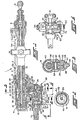
- Figure 1 is a fragmentary longitudinal section through a fluid actuator and sequence-power valve in accordance with the present invention;
- Figure 2 is an enlarged transverse section through the valve of Figure 1 taken on the plane of the line 2-2 thereof to show the interconnection between the lock valve and lock plunger;
- Figure 3 is an enlarged fragmentary transverse section through the valve and lock mechanism of Figure 1 taken along the plane of the line 3-3 thereof to show the interconnection between the lock plunger and movable lock part;
- Figure 4 is an enlarged fragmentary plan view of the valve of Figure 1 with portions broken away substantially along the plane of the line 4-4 to show the return flow path from the actuator bypassing the lock valve; and
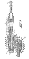
- Figure 5 is a fragmentary longitudinal section through the actuator and valve similar to Figure 1, but showing the lock disengaged by actuation of the valve and the valve in a position providing for direct flow of fluid through the valve to the extend side of the actuator.
- Referring now in detail to the drawings, and initially to Fig. 1 thereof, there is shown a fluid actuator 1 including a
cylinder 2 containing apiston 3 axially movable therewithin. Attached to the piston is ahollow rod 4 which extends through therod end 5 of the cylinder and has a rod end assembly 6 on its outboard end to facilitate connection to the movable or stationary part of the device to be actuated, for example, the thrust reversers for a jet engine on an aircraft. A suitable trunnion mount 8 may also be provided on the cylinder to facilitate connection to the other part of the device to be actuated. - The
piston 3 has a highlead Acme nut 9 in the center thereof which is coupled to a matingAcme screw shaft 10. One end of the screw shaft may be journaled insuitable bearings 11 within anactuator housing 12 attached to the head end of the cylinder. The other end of the screw shaft extends into the hollow piston rod 4 a substantial distance beyond the nut. As the piston moves back and forth in the cylinder, the screw shaft rotates at a speed proportional to the velocity of the piston. - The
screw shaft 10 has a highlead worm wheel 15 attached thereto which mates with aworm shaft 16 mounted for rotation within a transverse bore 17 in the actuator housing. Since the speed of the worm shaft is also proportional to the velocity of the piston rod, when the worm shafts of two or more actuators are connected together by a synchronous drive shaft or the like, they will be mechanically synchronized in both position and motion, as well known in the art. - When the actuator is in the retracted or stowed position shoen in Fig. 1, such actuator may be locked in such position by a
lock mechanism 18 which may include amovable lock sleeve 19 axially movable within the actuator housing toward and away from the adjacent end of theworm gear 15. Thelock sleeve 19 has acentral opening 20 through which thescrew shaft 10 extends, with sufficient clearance therebetween to permit rotation of the screw shaft relative to the lock sleeve. To prevent rotation of the lock sleeve within theactuator housing 12 while permitting limited axial movement therewithin, asplined connection 21 is provided between the movable lock sleeve and apiston stop 22 within the actuator housing. - The adjacent end faces of the
worm gear 15 andmovable lock sleeve 19 have cooperatinglock teeth 23 thereon with ramp angles which when engaged permit ratcheting of the worm gear relative to the movable lock sleeve during retraction of the piston but not during extension thereof. Accordingly, the piston will continue to retract until it engages theretract stop 22. However, if at any time during such ratcheting an attempt is made to reverse the piston direction, the lock teeth will instantly engage thus locking thescrew shaft 10 against rotation and preventing the piston from extending. - When the
piston 2 is fully retracted, themovable lock sleeve 19 is normally maintained in engagement with theworm gear 15 by alock spring 26 interposed between the movable lock sleeve andpiston head 28. During retraction of the actuator, as the piston approaches the end of its stroke, the piston head compresses the lock spring, causing the teeth on the movable lock sleeve to move into engagement with the teeth on the worm gear. - Before the actuator can be extended, the
lock sleeve 19 must be moved away from theworm gear 15 to disengage thelock teeth 23, and then system pressure must be applied to the extendedside 29 of the actuator. In accordance with the present invention, both such functions are accomplished by actuation of a sequence-power valve 30, the details of which will be described hereafter. Such sequence-power valve may be contained in aseparate housing 31 having a generallyright angle extension 32 at one end adapted to be received in avalve port 33 in one side of theactuator housing 12 and releasably retained in place as bybolts 34 or the like (see Fig. 4). The extension contains atransverse bore 35 in which a toggle typelock release lever 36 is mounted on ashaft 37 for limited pivotal movement. The inner end of the lock release lever extends into the actuator housing and has afork 38 thereon surrounding themovable lock sleeve 19. When thelever 36 is pivoted about theshaft 37 in a generally clockwise direction as viewed in Figs. 1 and 5, thefork 38 will engage ashoulder 40 on the movable lock sleeve thus forcing the movable lock sleeve out of engagement with theworm gear 15 as shown in Fig. 5. - For effecting such pivotal movement of the lock release lever, a
movable lock plunger 45 is provided in alongitudinal bore 46 in the sequence-power valve housing 31 extending in a direction generally parallel to the longitudinal axis of the actuator cylinder. The lock plunger has alongitudinal slot 47 therein which receives theouter end 48 of thelock release lever 36. - Also contained in the
longitudinal bore 46 adjacent one end of thelock plunger 45 is alock piston 50. To facilitate attachment of the lock plunger to the lock piston, the lock piston has astem 51 on the inner end thereof which is received in alongitudinal slot 52 in the outer end of the lock plunger. At the innermost end of the stem is a flange orshoulder 53 which is received in atransverse slot 54 in the lock plunger intersecting the inner end of thelongitudinal slot 52. Bothsuch slots lock plunger 45 from the same side as shown in Fig. 2 to permit the stem and flange to be inserted therein before the Icok plunger and piston are inserted into thelongitudinal bore 46. Such a connection between thelock plunger 45 andpiston 50 will take care of any slight axial misalignment that may exist between these two parts, thus eliminating the need for having to make them perfectly concentric. - The
lock piston 50 has adifferential area 58 which is acted upon by fluid pressure admitted to a lock-inannulus 59 within thebore 46 through an exterior port 60 (see Fig. 4) to cause thelock piston 50 to move to the left as viewed in Figs. 1 and 5, dragging thelock plunger 45 with it. This causes the lock release lever 36 to pivot about theshaft 37 and move thelock sleeve 19 axially inwardly against the force of thelock spring 26 to disengage the lock sleeve from the worm gear as shown in Fig. 5. - Before system pressure is admitted to the lock-in
annulus 59 for effecting release of the lock, such system pressure is desirably applied to theretract side 62 of the actuator through aretract port 63 and portingtube 64 to remove any axial tension loads on the actuator which might otherwise interface with release of the lock. Then, with system pressure still applied to the retract port, system pressure is also applied to the lock-inannulus 59 to release the lock in the manner previously described. - After the
lock piston 50 has moved far enough to release the lock, the system pressure acting on the lock piston is ported to theextend side 29 of the actuator through anotherannulus 65 in thelock piston bore 46 which is uncovered by the lock piston following such movement as shown in Fig. 5. This annulus communicates with the extend side of the actuator through apassageway 66 in the sequence-power valve housing 31 which is connected to the outer end of thetransverse bore 35 in such housing. The fluid entering such transverse bore flows around thelock plunger 45 andlock release lever 36 and into the extend side of the actuator through thevalve port 33 in theactuator housing 12. Since the area of thepiston 3 exposed to the extend pressure is greater than that exposed to the retract pressure, the actuator will extend. As it does so, the piston moves away from thelock spring 26, thus causing the lock spring to be fully extended, at which point it is no longer effective in applying a locking force to themovable lock sleeve 19. - If during extension of the actuator the system pressure should drop sufficiently, a
return spring 70 acting on the outer end of thelock piston 50 may start to return the lock piston and plunger 45 to their original position. However, atorsion spring 71 acting on thelock release lever 36 will still maintain themovable lock sleeve 19 out of engagement with theworm wheel 15 so that the actuator does not suddenly stop. Any such return movement of the lock piston and plunger will not affect the position of the lock release lever because of the length of theslot 47 in the lock plunger which accommodates such movement. However, such return movement of the lock piston could cut down the flow of fluid through theannulus 65 to the extend side of the actuator. To reduce the possibility of that happening when the extend pressure decreases due, for example, to an aiding air load pulling the actuator out, a restrictor 72 may be provided in thepassageway 66 communicating with theannulus 65 to help maintain the pressure on the lock piston high enough such that it will not cycle during extension of the actuator. - To retract the actuator, the pressure acting on the extend side of the actuator is reduced, as by connecting the
port 60 and thus the lock-inannulus 59 in communication therewith to return pressure, while still maintaining system pressure on the retract side of the actuator. With reduced pressure at the lock-in annulus, thereturn spring 70 acting on thelock piston 50 will cause the lock piston to return to its original position blocking fluid flow from the extend side of the actuator through thelock valve 50. However, return flow from the extend side of the actuator still occurs through acheck valve 75 in anotherpassage 76 in thevalve housing 31 providing communication between theannulus 65 andannulus 59 through such check valve as shown in Fig. 4. - As the actuator retracts, the lock is prevented from prematurely engaging by the
torsion spring 71 which maintains thelock release lever 36 in the unlocking position shown in Fig. 5 until thepiston 3 engages thelock spring 26 and compresses same sufficiently to overcome the relatively light force of the torsion spring and force thelock teeth 23 into engagement. This normally occurs within the last 0.8 cm (3/10 inch) or so of the retract stroke. However, the actuator will continue to move in the stow direction until the actuator piston engages theinternal stop 22 because of the torque developed by thescrew shaft 10 and the ramp angles of thelock teeth 23 which cause the lock teeth to ratchet over each other. When the actuator piston engages the retract stop, the screw shaft also stops, and since the lock teeth are already in engagement with each other, any motion that tends to extend the actuator will cause the locking faces of the lock teeth to engage thus providing a positive lock against such motion. - From the foregoing, it will now be apparent that the sequence-power valve of the present invention not only releases the lock mechanism for the actuator when fluid pressure is applied thereto, but such valve also ports such fluid pressure directly to the actuator to cause same to move in the desired direction following release of the lock. Accordingly, the need for a separate valve member and the associated external tubing for interconnecting the parts to supply fluid pressure to the actuator after the actuator has been unlocked is eliminated. Provision is also made for maintaining the valve mechanism substantially fully open for maximum flow to the actuator during actuation thereof despite fluctuations in such fluid pressure. Moreover, once the lock mechanism is disengaged, such disengagement is assured until such time as the actuator is returned to the original position at which reengagement of the lock occurs.
Claims (10)
Applications Claiming Priority (2)
| Application Number | Priority Date | Filing Date | Title |
|---|---|---|---|
| US06/352,046 US4463657A (en) | 1982-02-24 | 1982-02-24 | Fluid actuator with sequence-power valve |
| US352046 | 1982-02-24 |
Publications (3)
| Publication Number | Publication Date |
|---|---|
| EP0087254A2 EP0087254A2 (en) | 1983-08-31 |
| EP0087254A3 EP0087254A3 (en) | 1984-09-19 |
| EP0087254B1 true EP0087254B1 (en) | 1987-09-30 |
Family
ID=23383568
Family Applications (1)
| Application Number | Title | Priority Date | Filing Date |
|---|---|---|---|
| EP83300721A Expired EP0087254B1 (en) | 1982-02-24 | 1983-02-14 | Fluid actuator with sequence-power valve |
Country Status (6)
| Country | Link |
|---|---|
| US (1) | US4463657A (en) |
| EP (1) | EP0087254B1 (en) |
| JP (1) | JPS58152909A (en) |
| CA (1) | CA1201339A (en) |
| DE (1) | DE3373929D1 (en) |
| IL (1) | IL67890A (en) |
Families Citing this family (9)
| Publication number | Priority date | Publication date | Assignee | Title |
|---|---|---|---|---|
| US4491059A (en) * | 1982-03-29 | 1985-01-01 | Pneumo Corporation | Fluid actuator with manual lock release and lock position sensor |
| DE3935443A1 (en) * | 1989-10-25 | 1991-05-02 | Daimler Benz Ag | LOCKING DEVICE, ESPECIALLY FOR A PRESSURE CONTROLLER OF THE AXIAL PISTON DESIGN |
| US5058385A (en) * | 1989-12-22 | 1991-10-22 | The United States Of America As Represented By The Secretary Of The Navy | Pneumatic actuator with hydraulic control |
| GB2265186A (en) * | 1992-03-21 | 1993-09-22 | David Richard Evans | Valve actuator |
| EP0801221A3 (en) * | 1996-04-09 | 1998-11-04 | Lucas Industries Public Limited Company | Actuating system for an aircraft thrust reverser |
| US6786039B2 (en) * | 2001-09-07 | 2004-09-07 | Honeywell International, Inc. | Thrust reverser actuator with an automatic relock and lock drop prevention mechanism |
| US6935097B2 (en) * | 2003-04-17 | 2005-08-30 | Honeywell International, Inc. | Lock assembly that inhibits thrust reverser movement at or near the stowed position |
| FR2989740B1 (en) * | 2012-04-23 | 2016-09-02 | Sagem Defense Securite | ACTUATING DEVICE FOR MOVING A MOBILE HOOD FROM A THRUST INVERTER |
| FR3150551B1 (en) * | 2023-06-27 | 2025-06-13 | Safran Nacelles | Lost motion actuation device for thrust reverser |
Citations (1)
| Publication number | Priority date | Publication date | Assignee | Title |
|---|---|---|---|---|
| US2349244A (en) * | 1942-02-26 | 1944-05-23 | Bendix Aviat Ltd | Actuating cylinder |
Family Cites Families (7)
| Publication number | Priority date | Publication date | Assignee | Title |
|---|---|---|---|---|
| US2535588A (en) * | 1945-08-20 | 1950-12-26 | Theodore E Mead | Fluid-driven impact mechanism |
| GB752612A (en) * | 1953-08-31 | 1956-07-11 | Gen Motors Corp | Improvements relating to fluid-pressure operated actuators |
| US3348454A (en) * | 1965-04-05 | 1967-10-24 | Plessey Uk Ltd | Actuating arrangements |
| US3442176A (en) * | 1967-05-01 | 1969-05-06 | Gen Electric | Actuator locking mechanism |
| US4267767A (en) * | 1979-07-02 | 1981-05-19 | Hiniker Company | Position lock |
| US4410561A (en) * | 1981-07-31 | 1983-10-18 | Bell Telephone Laboratories, Incorporated | Method of forming coated optical fiber |
| JPS5852305A (en) * | 1981-09-25 | 1983-03-28 | Japan Synthetic Rubber Co Ltd | Polymer or copolymer containing polar group |
-
1982
- 1982-02-24 US US06/352,046 patent/US4463657A/en not_active Expired - Fee Related
-
1983
- 1983-02-09 CA CA000421251A patent/CA1201339A/en not_active Expired
- 1983-02-11 IL IL67890A patent/IL67890A/en unknown
- 1983-02-14 EP EP83300721A patent/EP0087254B1/en not_active Expired
- 1983-02-14 DE DE8383300721T patent/DE3373929D1/en not_active Expired
- 1983-02-15 JP JP58022244A patent/JPS58152909A/en active Pending
Patent Citations (1)
| Publication number | Priority date | Publication date | Assignee | Title |
|---|---|---|---|---|
| US2349244A (en) * | 1942-02-26 | 1944-05-23 | Bendix Aviat Ltd | Actuating cylinder |
Also Published As
| Publication number | Publication date |
|---|---|
| IL67890A (en) | 1986-11-30 |
| EP0087254A2 (en) | 1983-08-31 |
| JPS58152909A (en) | 1983-09-10 |
| CA1201339A (en) | 1986-03-04 |
| US4463657A (en) | 1984-08-07 |
| DE3373929D1 (en) | 1987-11-05 |
| EP0087254A3 (en) | 1984-09-19 |
Similar Documents
| Publication | Publication Date | Title |
|---|---|---|
| RU2120559C1 (en) | Mechanical lock for jet engine thrust reverser | |
| US7174828B2 (en) | Linear actuator | |
| US5310138A (en) | Wing fold actuator system for aircraft | |
| DE69517678T2 (en) | Lock for a synchronization shaft of a thrust reverser | |
| EP0087255B1 (en) | Fluid actuator with remote lock release assembly | |
| DE69207851T2 (en) | Locking of a thrust reverser | |
| US4463657A (en) | Fluid actuator with sequence-power valve | |
| EP0102684B1 (en) | Fluid actuator with feedback mechanism | |
| KR100417208B1 (en) | Lock for nozzle control in the event of hydraulic failure | |
| EP0090541B1 (en) | Fluid actuator with manual lock release and lock position sensor | |
| EP0090540B1 (en) | Fluid actuator with lock position indicating means | |
| EP0801221A2 (en) | Actuating system for an aircraft thrust reverser | |
| CA1176478A (en) | Propeller brake for a turbo-prop engine | |
| US4841844A (en) | Fluid actuators with LVDT feedback mechanisms | |
| US6138449A (en) | Lock for a thrust reverser mechanism and a thrust reverser mechanism | |
| EP0087256B1 (en) | Fluid pressure actuator with stroke end lock mechanism | |
| CN1174934A (en) | Thrust reverster synchronization shaft lock | |
| US4562909A (en) | Clutch device for marine vessel drive | |
| EP0102138B1 (en) | Actuator system including hydraulically synchronized actuators | |
| US3713518A (en) | Decoupler control | |
| RU2152528C1 (en) | Thrust reverser synchronization shaft locking system and synchronization shaft lock |
Legal Events
| Date | Code | Title | Description |
|---|---|---|---|
| PUAI | Public reference made under article 153(3) epc to a published international application that has entered the european phase |
Free format text: ORIGINAL CODE: 0009012 |
|
| AK | Designated contracting states |
Designated state(s): BE DE FR GB IT |
|
| PUAL | Search report despatched |
Free format text: ORIGINAL CODE: 0009013 |
|
| AK | Designated contracting states |
Designated state(s): BE DE FR GB IT |
|
| 17P | Request for examination filed |
Effective date: 19850301 |
|
| 17Q | First examination report despatched |
Effective date: 19860512 |
|
| RAP1 | Party data changed (applicant data changed or rights of an application transferred) |
Owner name: PNEUMO ABEX CORPORATION |
|
| GRAA | (expected) grant |
Free format text: ORIGINAL CODE: 0009210 |
|
| AK | Designated contracting states |
Kind code of ref document: B1 Designated state(s): BE DE FR GB IT |
|
| PG25 | Lapsed in a contracting state [announced via postgrant information from national office to epo] |
Ref country code: IT Free format text: LAPSE BECAUSE OF FAILURE TO SUBMIT A TRANSLATION OF THE DESCRIPTION OR TO PAY THE FEE WITHIN THE PRESCRIBED TIME-LIMIT;WARNING: LAPSES OF ITALIAN PATENTS WITH EFFECTIVE DATE BEFORE 2007 MAY HAVE OCCURRED AT ANY TIME BEFORE 2007. THE CORRECT EFFECTIVE DATE MAY BE DIFFERENT FROM THE ONE RECORDED. Effective date: 19870930 Ref country code: BE Effective date: 19870930 |
|
| REF | Corresponds to: |
Ref document number: 3373929 Country of ref document: DE Date of ref document: 19871105 |
|
| ET | Fr: translation filed | ||
| PLBE | No opposition filed within time limit |
Free format text: ORIGINAL CODE: 0009261 |
|
| STAA | Information on the status of an ep patent application or granted ep patent |
Free format text: STATUS: NO OPPOSITION FILED WITHIN TIME LIMIT |
|
| 26N | No opposition filed | ||
| PGFP | Annual fee paid to national office [announced via postgrant information from national office to epo] |
Ref country code: FR Payment date: 19900202 Year of fee payment: 8 |
|
| PGFP | Annual fee paid to national office [announced via postgrant information from national office to epo] |
Ref country code: DE Payment date: 19900227 Year of fee payment: 8 |
|
| PGFP | Annual fee paid to national office [announced via postgrant information from national office to epo] |
Ref country code: GB Payment date: 19900228 Year of fee payment: 8 |
|
| PG25 | Lapsed in a contracting state [announced via postgrant information from national office to epo] |
Ref country code: GB Effective date: 19910214 |
|
| GBPC | Gb: european patent ceased through non-payment of renewal fee | ||
| PG25 | Lapsed in a contracting state [announced via postgrant information from national office to epo] |
Ref country code: FR Effective date: 19911031 |
|
| PG25 | Lapsed in a contracting state [announced via postgrant information from national office to epo] |
Ref country code: DE Effective date: 19911101 |
|
| REG | Reference to a national code |
Ref country code: FR Ref legal event code: ST |