EP0084739A1 - Snap-on liquid tight connector for flexible metal conduit - Google Patents
Snap-on liquid tight connector for flexible metal conduit Download PDFInfo
- Publication number
- EP0084739A1 EP0084739A1 EP82307033A EP82307033A EP0084739A1 EP 0084739 A1 EP0084739 A1 EP 0084739A1 EP 82307033 A EP82307033 A EP 82307033A EP 82307033 A EP82307033 A EP 82307033A EP 0084739 A1 EP0084739 A1 EP 0084739A1
- Authority
- EP
- European Patent Office
- Prior art keywords
- connector
- conduit
- electrical enclosure
- housing
- electrical
- Prior art date
- Legal status (The legal status is an assumption and is not a legal conclusion. Google has not performed a legal analysis and makes no representation as to the accuracy of the status listed.)
- Withdrawn
Links
Images

Classifications
-
- H—ELECTRICITY
- H02—GENERATION; CONVERSION OR DISTRIBUTION OF ELECTRIC POWER
- H02G—INSTALLATION OF ELECTRIC CABLES OR LINES, OR OF COMBINED OPTICAL AND ELECTRIC CABLES OR LINES
- H02G3/00—Installations of electric cables or lines or protective tubing therefor in or on buildings, equivalent structures or vehicles
- H02G3/02—Details
- H02G3/06—Joints for connecting lengths of protective tubing or channels, to each other or to casings, e.g. to distribution boxes; Ensuring electrical continuity in the joint
- H02G3/0616—Joints for connecting tubing to casing
Definitions
- This invention relates to connectors for connecting flexible conduit to an electrical junction box and more particularly relates to a connector which is liquid-tight and can snap onto the junction box.
- a connector In connecting conduit containing electrical cables to a junction box, a connector is employed which not only mechanically connects the conduit to the box but also desirably provides electrical connection, i.e., ground connection therebetween.
- electrical connection i.e., ground connection therebetween.
- the ground connection is usually made between the metallic conduit itself and the Junction box.
- a connector In order to provide a suitable liquid-tight connection, a connector is commonly employed that includes a metallic grounding ring to electrically connect the metal cable to the box, and a resilient sealing ring which provides the liquid-tight seal between the connector and the box.
- the body of the structure is usually screw-threaded for screw- tight attacnment to the box.
- a gland nut is employed to urge the sealing ring against the enclosure for a liquid-tight seal.
- a lock nut is then. used to secure the combination. Once the sealing ring is compressed as by screw tightening the gland nut, it usually will not sufficiently recover so as to be reusable for further connections.
- a multi-piece unit of this type is costly, both to manufacture and securely install in the junction box. The connector would also be subject to being shaken loose in response to vibratory forces. Additionally, individual components of these multi-piece units can be lost or destroyed, rendering the entire unit useless.
- the invention looks toward providing a connector which receives the end of a flexible metallic conduit in liquid-tight relation.
- the connector then can be resiliently secured to an electrical enclosure, providing mechanical and electrical connection-
- the invention further looks to providing a housing body which couples in liquid-tight relation with the metallic conduit and further couples with the electrical enclosure.
- a unitary body having an opening which connects with a metallic conduit in liquid-tight relation.
- the body contains a metallic grounding ferrule which electrically connects to the metallic conduit.
- the body then extends to connect with the junction box by employing integral snap members which engage the inside wall of the electrical enclosure.
- the grounding ferrule similarly extends to make electrical connection with the electrical enclosure.
- An alternate embodiment includes a grounding ferrule having resilient clips which, in addition to electrically connecting the connector, also mechanically affixes the connector to the electrical enclosure.
- the connector 10 of the present invention includes an outer housing 20, sealing washer 40, grounding ferrule 60 and may also include an insulated throat 80.
- Housing 20 has a generally hollow cylindrical shape, having a conduit receiving section 22 and an insertion section 24 divided transversly by annular shoulder 26 which -extends both radially outwardly and inwardly of housing 20.
- housing 10 is a unitary member formed of plastic or similar material, though it is contemplated that any rigid material, including metal, may be employed.
- Conduit receiving section 22 is adapted to connect with flexible metal conduit 11 (shown in phantom) in liquid tight relation.
- the internal wall 23 of receiving section 22 is tapered so that the internal diameter of section 22 is greater at its distal outer extent than at its inner extent.
- annular rib 25 protrudes from and circumscribes the internal wall 23 of receiving section 22 to further constrict the internal diameter.
- the metallic conduit 11 inserted therein will wedge against the narrower inner portion of internal wall 23 thereby forming a liquid-tight seal therebetween in assembly.
- the annular rib 25 will bear inwardly against conduit 11 constricting its edge to secure the conduit in sealed position in receiving section 22.
- Annular rib 25 prevents gathering of an outer jacket (not shown) which may surround the metallic conduit and further provides prevention of inadventent pull out.
- Shoulder 26 lies in a plane which transversly cuts the cylinder of housing 20, and has an outwardly projecting extent 28 extending adjacent to the electrical enclosure 12, as shown in Fig. 2.
- Resilient sealing washer 40 is disposed between the inner wall of shoulder extent 28 and the outer wall 29 of the electrical enclosure 12 to insure a secure connection.”
- Insertion section 24 of housing 20 is adapted to be inserted into an opening or knock-out of the electrical enclosure 12, having a smaller outer diameter than conduit receiving section 22.
- Extending from the outer surface of insertion section 24 are a series of spaced apart resilient locking tabs 30 which serve to secure the housing to the electrical enclosure.
- Locking tabs 30 have tapered side walls 32 and flat land portions 34 which are parallel to the wall of shoulder extent 28. Locking tabs 30 are disposed so as to snap into and engage the inside surface of wall 29 of the electrical enclosure adjacent the knock-out upon insertion of the insertion end 24 of housing 20.
- the distance between flat lands 34 and the inside wall of shoulder extent 28 is such that sealing washer 40 will be compressed in assembly, forming thereby a liquid-tight connection.
- a series of slots 35 are located at spaced apart positions on the outside of insertion portion 24.
- the slots 34 accommodate outwardly extending grounding tabs 70 on the grounding ferrule 60 to permit contact with the wall of the electrical enclosure as will be described hereinafter.
- grounding ferrule 60 which is slidably inserted through the insertion end of housing 20.
- Grounding ferrule 60 has a cylindrical conduit contacting section 62 having a helically configured outer edge 64 which can be screw threaded into the inside wall of metallic conduit 11. This screw-type relation securely connects grounding ferrule 60 to conduit 11 and provides electrical contact therebetween.
- a mid-section 66 of grounding ferrule 60 is frustoconical in shape, having a wide portion forming a stop which engages the inwardly extending section 27 of shoulder 26, thereby preventing axial displacement of the grounding ferrule 60.
- a cylindrical insertion end 68 of grounding ferrule 60 Extending from the wider end of frustoconical mid- section 66 is a cylindrical insertion end 68 of grounding ferrule 60. Insertion end 68 has a series of outwardly extending grounding tabs 70 which are disposed in registry with slots 35 of housing 20. Grounding tabs 70 extend out beyond the outer wall of housing 20 to contact, upon insertion, the inner peripheral wall 14 of the electrical enclosure 12, establishing electrical connection therebetween. As grounding tabs 70 are resiliently bendable, they may be force fitted into the knock-out of the electrical enclosure 12 wherein they provide a bias against the inner peripheral wall 14.
- An insulated throat 80 which may surround the outer extent of insertion end 24 of housing 20, serves to buffer the edge of the housing. Throat 80 protects electrical cable (not shown) which extends through the connector from contacting the edge of the housing or the grounding ferrule.
- connection can be made between flexible metallic conduit and an electrical enclosure in the following manner.
- Connector 10 can be screw-threaded onto the end of a flexible metallic conduit 11 using the screw-threaded outer edge 64 of grounding ferrule 60 to engage the inner metallic portion of the conduit 11 and tightened down until the outer edge lla of the conduit wedges against the tapered inner wall 23 of the receiving section 22 below annular rib 25.
- This relation creates a liquid-tight seal between the housing 20 and the conduit and additionally anchors the conduit securely in the receiving section 22, preventing inadventent pull out.
- This relation also establishes electrical connection between the conduit to the grounding ferrule 60.
- the insertion end 24 of housing 20 is then snapped into the knock-out of an electrical enclosure.
- Resilient locking tabs 30 bend inwardly upon insertion, then recover to snap on to the inside surface of the electrical enclosure 12, thus mechanically mounting the connection 10 to the enclosure.
- Grounding tabs 70 which extend outwardly from slots 35 of insertion end 24, preferably engage the peripheral wall 14 of the knock-out, thereby providing electrical contact thereto.
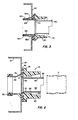
- FIG. 3 An alternative embodiment of the preferred invention is shown in Fig. 3. As the embodiment of Fig. 3 is substantially similar to that of Figs. 1 and 2, similar reference numerals will be used to denote similar elements with 100 being added to the reference characters of Figs 1 and 2.
- Connector 110 includes outer cylindrical housing 120, sealing washer 140 and grounding ferrule 160.
- Grounding ferrule 160 and the insertion section 124 of housing 120 have been modified so that the grounding ferrule 160 provides both mechanical and electrical connection to the electrical enclosure 112.
- the insertion section 124 is a hollow cylinder, having no slots or locking tabs.
- grounding ferrule 160 also has a hollow cylindrical insertion end 168 without grounding tabs.
- grounding ferrule 160 includes a pair of peripherally spaced resilient clips 164 and 165, diametrically opposed and extending from the insertion edge 167 of grounding ferrule 160, circumferentially exteriorly of and back along the longitudinal extent of the grounding ferrule to a point just proximal of the frustoconical midsection 166.
- clips 164 and 165 form a pair of open-ended chambers at the insertion end of the grounding ferrule.
- the outer extents 164a and 165a of the respective clips, adjacent the frustoconical midsection 166 are flanged to incline outwardly for engagement with the inside wall of electrical enclosure 112.
- the resilient clips In inserting the connector into the knock-out of the electrical enclosure 112, the resilient clips will bend inwardly, then recover to engage the inside surface of the electrical enclosure. This contact will not only provide electrical connection between the connector and the electrical enclosure, but will also provide mechanical securement therebetween.
Abstract
A snap-on liquid tight connector (10) for mechanically and electrically connecting a flexible metallic conduit (11) to an electrical enclosure (12) is screw-threaded at the conduit receiving end (22, 62) for electrical- contact thereto and for secure, liquid tight engagement. The opposite end of the connector is snapped into the knock-out of an electrical enclosure (12). The insertion end (68) of the connector provides both electrical and mechanical connection between the connector and the electrical enclosure.
Description
- This invention relates to connectors for connecting flexible conduit to an electrical junction box and more particularly relates to a connector which is liquid-tight and can snap onto the junction box.
- In connecting conduit containing electrical cables to a junction box, a connector is employed which not only mechanically connects the conduit to the box but also desirably provides electrical connection, i.e., ground connection therebetween. When employing a metallic raceway or flexible metallic conduit, the ground connection is usually made between the metallic conduit itself and the Junction box.
- In order to provide a suitable liquid-tight connection, a connector is commonly employed that includes a metallic grounding ring to electrically connect the metal cable to the box, and a resilient sealing ring which provides the liquid-tight seal between the connector and the box. The body of the structure is usually screw-threaded for screw- tight attacnment to the box.
- A gland nut is employed to urge the sealing ring against the enclosure for a liquid-tight seal. A lock nut is then. used to secure the combination. Once the sealing ring is compressed as by screw tightening the gland nut, it usually will not sufficiently recover so as to be reusable for further connections. Further, a multi-piece unit of this type is costly, both to manufacture and securely install in the junction box. The connector would also be subject to being shaken loose in response to vibratory forces. Additionally, individual components of these multi-piece units can be lost or destroyed, rendering the entire unit useless.
- It is thereby desirable to have a connector which will result in more efficient connection and a product which is less costly to manufacture and install than is presently available.
- It is an object of the present invention to provide improved metallic conduit connectors.
- It is a more particular object of the invention to provide an improved liquid-tight connector for metallic conduits which resiliently mounts onto an electrical enclosure for secure mechanical and electrical connection.
- In the attainment of the foregoing and other objects, the invention looks toward providing a connector which receives the end of a flexible metallic conduit in liquid-tight relation. The connector then can be resiliently secured to an electrical enclosure, providing mechanical and electrical connection- The invention further looks to providing a housing body which couples in liquid-tight relation with the metallic conduit and further couples with the electrical enclosure.
- In a particularly described embodiment a unitary body is employed, having an opening which connects with a metallic conduit in liquid-tight relation. The body contains a metallic grounding ferrule which electrically connects to the metallic conduit. The body then extends to connect with the junction box by employing integral snap members which engage the inside wall of the electrical enclosure. The grounding ferrule similarly extends to make electrical connection with the electrical enclosure.
- An alternate embodiment includes a grounding ferrule having resilient clips which, in addition to electrically connecting the connector, also mechanically affixes the connector to the electrical enclosure.
- Other objects and features of the invention will be evident from the following detailed description of preferred embodiments and from the drawings herein.
-
- Fig. 1 is a perspective showing, partially in section of the snap-on liquid-tight connector of the present invention, with the flexible conduit shown in phantom.
- Fig. 2 is a longitudinal cross-section of the connector of Fig. 1 as attached to a junction box.
- Fig. 3 is a longitudinal cross-section of an alternative embodiment of the present invention, having a mechanical and electrical grounding ferrule.
- Referring to Figs. 1 and 2, the
connector 10 of the present invention includes anouter housing 20, sealingwasher 40, groundingferrule 60 and may also include aninsulated throat 80. -
Housing 20 has a generally hollow cylindrical shape, having aconduit receiving section 22 and aninsertion section 24 divided transversly byannular shoulder 26 which -extends both radially outwardly and inwardly ofhousing 20. In preferred form,housing 10 is a unitary member formed of plastic or similar material, though it is contemplated that any rigid material, including metal, may be employed. -
Conduit receiving section 22 is adapted to connect with flexible metal conduit 11 (shown in phantom) in liquid tight relation. Theinternal wall 23 of receivingsection 22 is tapered so that the internal diameter ofsection 22 is greater at its distal outer extent than at its inner extent. - An
annular rib 25 protrudes from and circumscribes theinternal wall 23 of receivingsection 22 to further constrict the internal diameter. Themetallic conduit 11 inserted therein will wedge against the narrower inner portion ofinternal wall 23 thereby forming a liquid-tight seal therebetween in assembly. Theannular rib 25 will bear inwardly againstconduit 11 constricting its edge to secure the conduit in sealed position in receivingsection 22.Annular rib 25 prevents gathering of an outer jacket (not shown) which may surround the metallic conduit and further provides prevention of inadventent pull out. -
Shoulder 26 lies in a plane which transversly cuts the cylinder ofhousing 20, and has an outwardly projectingextent 28 extending adjacent to theelectrical enclosure 12, as shown in Fig. 2.Resilient sealing washer 40 is disposed between the inner wall ofshoulder extent 28 and theouter wall 29 of theelectrical enclosure 12 to insure a secure connection." -
Insertion section 24 ofhousing 20 is adapted to be inserted into an opening or knock-out of theelectrical enclosure 12, having a smaller outer diameter thanconduit receiving section 22. Extending from the outer surface ofinsertion section 24 are a series of spaced apartresilient locking tabs 30 which serve to secure the housing to the electrical enclosure.Locking tabs 30 have taperedside walls 32 andflat land portions 34 which are parallel to the wall ofshoulder extent 28.Locking tabs 30 are disposed so as to snap into and engage the inside surface ofwall 29 of the electrical enclosure adjacent the knock-out upon insertion of theinsertion end 24 ofhousing 20. The distance betweenflat lands 34 and the inside wall ofshoulder extent 28 is such that sealingwasher 40 will be compressed in assembly, forming thereby a liquid-tight connection. - A series of
slots 35 are located at spaced apart positions on the outside ofinsertion portion 24. Theslots 34 accommodate outwardly extendinggrounding tabs 70 on thegrounding ferrule 60 to permit contact with the wall of the electrical enclosure as will be described hereinafter. - Electrical connection between
metal conduit 11 and theenclosure 12 is provided bymetallic grounding ferrule 60 which is slidably inserted through the insertion end ofhousing 20.Grounding ferrule 60 has a cylindricalconduit contacting section 62 having a helically configuredouter edge 64 which can be screw threaded into the inside wall ofmetallic conduit 11. This screw-type relation securely connects groundingferrule 60 to conduit 11 and provides electrical contact therebetween. - A mid-section 66 of
grounding ferrule 60 is frustoconical in shape, having a wide portion forming a stop which engages the inwardly extendingsection 27 ofshoulder 26, thereby preventing axial displacement of thegrounding ferrule 60. - Extending from the wider end of frustoconical mid-
section 66 is acylindrical insertion end 68 of groundingferrule 60.Insertion end 68 has a series of outwardly extendinggrounding tabs 70 which are disposed in registry withslots 35 ofhousing 20.Grounding tabs 70 extend out beyond the outer wall ofhousing 20 to contact, upon insertion, the innerperipheral wall 14 of theelectrical enclosure 12, establishing electrical connection therebetween. Asgrounding tabs 70 are resiliently bendable, they may be force fitted into the knock-out of theelectrical enclosure 12 wherein they provide a bias against the innerperipheral wall 14. - An insulated
throat 80 which may surround the outer extent of insertion end 24 ofhousing 20, serves to buffer the edge of the housing.Throat 80 protects electrical cable (not shown) which extends through the connector from contacting the edge of the housing or the grounding ferrule. - Employing the connector of the present invention, connection can be made between flexible metallic conduit and an electrical enclosure in the following manner.
-
Connector 10 can be screw-threaded onto the end of a flexiblemetallic conduit 11 using the screw-threadedouter edge 64 of groundingferrule 60 to engage the inner metallic portion of theconduit 11 and tightened down until the outer edge lla of the conduit wedges against the taperedinner wall 23 of the receivingsection 22 belowannular rib 25. This relation creates a liquid-tight seal between thehousing 20 and the conduit and additionally anchors the conduit securely in the receivingsection 22, preventing inadventent pull out. This relation also establishes electrical connection between the conduit to thegrounding ferrule 60. The insertion end 24 ofhousing 20 is then snapped into the knock-out of an electrical enclosure.Resilient locking tabs 30 bend inwardly upon insertion, then recover to snap on to the inside surface of theelectrical enclosure 12, thus mechanically mounting theconnection 10 to the enclosure. Groundingtabs 70, which extend outwardly fromslots 35 ofinsertion end 24, preferably engage theperipheral wall 14 of the knock-out, thereby providing electrical contact thereto. - An alternative embodiment of the preferred invention is shown in Fig. 3. As the embodiment of Fig. 3 is substantially similar to that of Figs. 1 and 2, similar reference numerals will be used to denote similar elements with 100 being added to the reference characters of Figs 1 and 2.
-
Connector 110, includes outercylindrical housing 120, sealing washer 140 and groundingferrule 160. - Grounding
ferrule 160 and theinsertion section 124 ofhousing 120 have been modified so that the groundingferrule 160 provides both mechanical and electrical connection to theelectrical enclosure 112. Theinsertion section 124 is a hollow cylinder, having no slots or locking tabs. Similarly, groundingferrule 160 also has a hollowcylindrical insertion end 168 without grounding tabs. - In the present embodiment, grounding
ferrule 160 includes a pair of peripherally spacedresilient clips ferrule 160, circumferentially exteriorly of and back along the longitudinal extent of the grounding ferrule to a point just proximal of thefrustoconical midsection 166. Thus, clips 164 and 165 form a pair of open-ended chambers at the insertion end of the grounding ferrule. Theouter extents 164a and 165a of the respective clips, adjacent thefrustoconical midsection 166 are flanged to incline outwardly for engagement with the inside wall ofelectrical enclosure 112. - In inserting the connector into the knock-out of the
electrical enclosure 112, the resilient clips will bend inwardly, then recover to engage the inside surface of the electrical enclosure. This contact will not only provide electrical connection between the connector and the electrical enclosure, but will also provide mechanical securement therebetween. - The above embodiments, shown and described, connect an extent of flexible conduit to an electrical enclosure at a straight-on or perpendicular direction. However, it is contemplated that curved connectors, i.e., with 90 degree, 45 degree, etc. bends, constructed in accordance with the present invention, may be employed to connect conduit to electrical enclosures at other than straight-on positions.
- Accordingly, the above-described embodiments are shown only by way of example and are in no sense limited to the particularly described features. The true spirit and scope of the invention are set forth in the claims appended hereto.
Claims (10)
1. A connector for coupling a flexible metallic conduit to an electrical enclosure having an opening comprising:
a housing, including means for receiving said conduit in liquid-tight relation;
a grounding element disposed in said housing for electrical engagement with said conduit;
means for electrically connecting said grounding element to said electrical enclosure;
means for resiliently securing said connector in said opening of said electrical enclosure.
2. The connector in accordance with claim 1 wherein said receiving means includes said housing being elongate and having a conduit receiving end; said conduit receiving end having a wall of inwardly decreasing internal dimension for receiving one end of said conduit therein and wherein said wall of said conduit receiving end includes an inwardly extending rib for securely engaging said conduit.
3. The connector in accordance with claim 1 or claim 2' wherein said resiliently securing means includes a resilient member, outwardly extending from said connector for securely-engaging said electrical enclosure.
4. The connector in accordance with claim 3 wherein said housing is elongate, having a cylindrical insertion portion for insertion into said opening of said electrical enclosure; said insertion portion having disposed about its outer surface said resilient member for securely engaging said electrical enclosure.
5. The connector in accordance with claim 4 wherein said resilient member includes a locking tab having a land portion thereon for engaging a wall-surface of said electrical enclosure adjacent said opening.
6. The connector in accordance with claim 4 wherein said resilient member includes a plurality of spaced-apart locking tabs, each having land portions thereon for engaging the wall surface of said electrical enclosure adjacent said opening.
7. The connector in accordance with any preceding claim wherein said electrical connection means includes a grounding member extending from said grounding element, said grounding member including a plurality of resilient grounding tabs for electrically contacting said electrical enclosure adjacent said opening.
8. The connector in accordance with claim 7 as dependent on claim 1 or claim 2 or claim 3 wherein resiliently securing means includes said grounding member.
9. The connector in accordance with claim 8 wherein said grounding member includes a plurality of resilient spaced-apart clips, said clips including flanged portions thereon for engaging a wall surface of said electrical enclosure adjacent said opening.
10. A connector for establishing an electrical and mechanical connection between a flexible metallic conduit and a metallic electrical enclosure having an opening therethrough comprising:
an elongate housing having a passage therethrough, said housing having a first end, including means for receiving said conduit in liquid-tight relation;
an elongate grounding element having a passage therethrough, said element disposed interiorly of said housing and said element including at a first end adjacent to said first end of said housing, first means for electrically contacting said conduit and second means, . disposed at the other end of said grounding element for electrically connecting said grounding element to said electrical enclosure; and
means for resiliently mounting said connector in said opening of said electrical enclosure.
Applications Claiming Priority (2)
| Application Number | Priority Date | Filing Date | Title |
|---|---|---|---|
| US06/335,528 US4468535A (en) | 1981-12-29 | 1981-12-29 | Snap-on liquid tight connector for flexible metal conduit |
| US335528 | 1981-12-29 |
Publications (1)
| Publication Number | Publication Date |
|---|---|
| EP0084739A1 true EP0084739A1 (en) | 1983-08-03 |
Family
ID=23312156
Family Applications (1)
| Application Number | Title | Priority Date | Filing Date |
|---|---|---|---|
| EP82307033A Withdrawn EP0084739A1 (en) | 1981-12-29 | 1982-12-22 | Snap-on liquid tight connector for flexible metal conduit |
Country Status (4)
| Country | Link |
|---|---|
| US (1) | US4468535A (en) |
| EP (1) | EP0084739A1 (en) |
| JP (1) | JPS58159612A (en) |
| CA (1) | CA1206991A (en) |
Cited By (1)
| Publication number | Priority date | Publication date | Assignee | Title |
|---|---|---|---|---|
| WO1988001447A1 (en) * | 1986-08-21 | 1988-02-25 | Elconnex Pty Limited | Junction box |
Families Citing this family (49)
| Publication number | Priority date | Publication date | Assignee | Title |
|---|---|---|---|---|
| US4621166A (en) * | 1983-08-15 | 1986-11-04 | Neuroth Robert J | Adjustable line covering electrical connector |
| US4816967A (en) * | 1984-11-14 | 1989-03-28 | Itt Gallium Arsenide Technology Center A Division Of Itt Corporation | Low impedance interconnect method and structure for high frequency IC such as GaAs |
| US4652018A (en) * | 1986-01-24 | 1987-03-24 | Paul Boghosian | Multi-fastening coupler for electrical conduit |
| CA1272499A (en) * | 1986-02-06 | 1990-08-07 | Commander Electrical Materials, Inc. | Connector for corrugated tubing |
| SE8602456L (en) * | 1986-05-30 | 1987-12-01 | Tage Skoenvall | PUT ON THE ORGANIZATION OF A BRANCH ON A RUDE |
| US4832119A (en) * | 1986-06-05 | 1989-05-23 | Bloor Trevor J | Multi-tube heat exchanger and connectors therefor |
| US4711472A (en) * | 1986-09-02 | 1987-12-08 | Hubbell Incorporated | Connector for non-metallic conduit |
| US4718703A (en) * | 1986-09-26 | 1988-01-12 | Harrell Joe S | Apparatus and method for interconnecting a reservoir with a rubber cup |
| US5068496A (en) * | 1990-10-31 | 1991-11-26 | Hubbell Incorporated | Snap-in connector |
| US5200575A (en) * | 1991-01-25 | 1993-04-06 | Sheehan Robert K | Connector assembly for conduit |
| US5204499A (en) * | 1991-05-03 | 1993-04-20 | Hubbell Incorporated | Snap-in connector with integral spring |
| US5346264A (en) * | 1992-03-19 | 1994-09-13 | Heyco Molded Products, Inc. | Liquid tight internal snap connector for connecting corrugated plastic conduit |
| US5295851A (en) * | 1992-10-02 | 1994-03-22 | Thomas & Betts Corporation | Electrical connector hub having improved sealing ring |
| US5422437A (en) * | 1993-04-16 | 1995-06-06 | Hubbell Incorporated | Electrical connector assembly |
| WO1995018482A1 (en) * | 1993-12-27 | 1995-07-06 | Sheehan Robert K | Snap-in locknut adapter for connectors |
| JP3638037B2 (en) * | 1995-05-23 | 2005-04-13 | 豊田合成株式会社 | Hose connector |
| US6043432A (en) * | 1998-01-15 | 2000-03-28 | Arlington Industries, Inc. | Snap in cable connector |
| US6670553B1 (en) * | 1998-01-15 | 2003-12-30 | Arlington Industries, Inc. | Snap engagement electrical fitting for EMT |
| EP0961375B1 (en) * | 1998-03-27 | 2001-05-16 | Bertoldo & C. Srl | A liquid-tight coupling for boxes for electric material |
| US6143983A (en) * | 1999-02-18 | 2000-11-07 | Emerson Electric Co. | Twist lock conduit connector grommet |
| DE69921499D1 (en) * | 1999-12-28 | 2004-12-02 | Bertoldo & C Srl | Fluid tight coupling |
| EP1180829A1 (en) * | 2000-08-17 | 2002-02-20 | C & C MARSHALL LIMITED | Connector for electrical, data or communications conduit |
| US6444907B1 (en) | 2001-05-01 | 2002-09-03 | Bridgeport Fittings, Inc. | Electrical cable connector |
| US20030226939A1 (en) * | 2002-06-07 | 2003-12-11 | Beck Jeremy M. | Grommet connector |
| US6719330B2 (en) * | 2002-06-18 | 2004-04-13 | Qest | Flexible tubing/fitting connection |
| US6860758B1 (en) * | 2002-10-30 | 2005-03-01 | Bridgeport Fittings, Inc. | Snap fitting electrical connector |
| CA2468274A1 (en) * | 2003-06-13 | 2004-12-13 | Thomas & Betts International, Inc. | Range taking snap-in connector |
| US6994382B2 (en) * | 2004-07-01 | 2006-02-07 | Visteon Global Technologies, Inc. | Retaining feature for corrugated acoustic duct |
| US6916988B1 (en) | 2004-07-12 | 2005-07-12 | Bridgeport Fittings, Inc. | Electrical connector with frustro conical snap fit retaining ring |
| US7045714B1 (en) | 2004-07-12 | 2006-05-16 | Bridgeport Fittings, Inc. | Electrical connector with conical snap fit retaining ring |
| US7214890B2 (en) | 2004-09-13 | 2007-05-08 | Bridgeport Fittings, Inc. | Electrical connector having an outlet end angularly disposed relative an inlet end with outer retainer ring about the outlet end and internal unidirectional conductor retainer in the inlet end |
| US7151223B2 (en) * | 2004-09-13 | 2006-12-19 | Bridgeport Fittings, Inc. | Snap fit electrical connector assembly with outer frustro conical retainer ring and internal unidirectional snap fit wire conductor retainer |
| US8350163B2 (en) | 2004-09-13 | 2013-01-08 | Bridgeport, Fittings, Inc. | Electrical connector having snap in frustro-conical retaining ring with improved conductivity |
| US7205489B2 (en) * | 2004-09-13 | 2007-04-17 | Bridgeport Fittings, Inc. | Snap fit electrical connector assembly with operating tool for facilitating the connection of a connector assembly to an electrical box |
| US7723623B2 (en) * | 2004-09-13 | 2010-05-25 | Bridgeport Fittings, Inc. | Electrical duplex connector having an integrally formed connector body with a frustro-conical retaining ring and unidirectional cable retainers |
| US7075007B2 (en) * | 2004-09-13 | 2006-07-11 | Bridgeport Fittings, Inc. | Snap fit electrical connector assembly with conical outer snap fit retainer and one or more internal snap fit wire retainers |
| US7952034B2 (en) * | 2004-09-13 | 2011-05-31 | Bridgeport Fittings, Inc. | Strap type electrical connector with frustro-conical retaining ring and improved clamping strap for either nonmetallic cables or armor or metal clad cables |
| US8119933B2 (en) * | 2004-09-13 | 2012-02-21 | Bridgeport Fittings, Inc. | Duplex electrical connector with frustro-conical retaining ring and crimped inlet end |
| US7358448B2 (en) * | 2004-09-13 | 2008-04-15 | Bridgeport Fittings, Inc. | Electrical connector assembly with frusto-conical snap fit retaining ring for enhancing electrical grounding of the connector assembly to an electrical box and installation tool therefor |
| US8143535B2 (en) * | 2004-09-13 | 2012-03-27 | Bridgeport Fittings, Inc. | Electrical connector assembly with enhanced grounding |
| US7154042B2 (en) * | 2004-09-13 | 2006-12-26 | Bridgeport Fittings, Inc. | Electrical connector with snap fit retainer ring constructed to enhance the connection of the connector to an electrical box |
| US7057107B2 (en) * | 2004-09-13 | 2006-06-06 | Bridgeport Fittings, Inc. | Snap fit electrical connector assembly with conical outer snap fit retainer and externally mounted internal wire retainer |
| US7488905B2 (en) * | 2004-09-13 | 2009-02-10 | Bridgeport Fittings, Inc. | Electrical connector with outer retainer ring and internal unidirectional conductor retainer |
| US7307218B2 (en) * | 2005-06-24 | 2007-12-11 | General Electric Company | One-piece cable armor ferrule |
| US20100084855A1 (en) * | 2008-10-07 | 2010-04-08 | Thomas & Betts International, Inc. | Economy liquidtight fitting |
| US8487196B1 (en) | 2009-06-26 | 2013-07-16 | Hubbell Incorporated | Box connector for electrical cable |
| US20120261003A1 (en) * | 2011-04-18 | 2012-10-18 | Fluidmaster, Inc. | Toilet Valve Adapter |
| US8910980B2 (en) * | 2011-11-08 | 2014-12-16 | Thomas & Betts International, Inc. | Liquid-tight fitting |
| US9726309B1 (en) * | 2013-03-13 | 2017-08-08 | Mercury Plastics, Inc. | Tube connection nut and ferrule assembly |
Citations (4)
| Publication number | Priority date | Publication date | Assignee | Title |
|---|---|---|---|---|
| FR2145190A5 (en) * | 1971-07-02 | 1973-02-16 | Smiths Industries Ltd | |
| US3858151A (en) * | 1973-06-04 | 1974-12-31 | Eaton Corp | Flexible conduit connector |
| US3902745A (en) * | 1974-01-02 | 1975-09-02 | Electrical Fittings Corp | Electrical connector |
| US4198537A (en) * | 1978-08-21 | 1980-04-15 | Thomas & Betts Corporation | Connector |
Family Cites Families (9)
| Publication number | Priority date | Publication date | Assignee | Title |
|---|---|---|---|---|
| US2744769A (en) * | 1954-03-25 | 1956-05-08 | Woodrow W Roeder | Bushing means for attaching cable in plate |
| US3183297A (en) * | 1962-10-24 | 1965-05-11 | Thomas & Betts Corp | Connector for outlet boxes |
| US3193613A (en) * | 1963-05-08 | 1965-07-06 | United Carr Inc | Combination conduit and wall connector device for the conduit |
| US3260790A (en) * | 1964-02-17 | 1966-07-12 | Alsup W Homer | Deformable non-metallic conduit coupling with grounding connections |
| US3349946A (en) * | 1965-08-09 | 1967-10-31 | Lee Hop | Electric outlet box |
| US3603912A (en) * | 1969-08-25 | 1971-09-07 | Thomas & Betts Corp | Raceway terminator |
| US3647934A (en) * | 1970-03-05 | 1972-03-07 | All Steel Equipment Inc | Liquidtight connector |
| US4021604A (en) * | 1975-04-14 | 1977-05-03 | Amp Incorporated | Flexible conduit connector |
| US4000918A (en) * | 1975-10-20 | 1977-01-04 | General Signal Corporation | Ferrule for liquid tight flexible metal conduit |
-
1981
- 1981-12-29 US US06/335,528 patent/US4468535A/en not_active Expired - Lifetime
-
1982
- 1982-12-16 CA CA000417897A patent/CA1206991A/en not_active Expired
- 1982-12-22 EP EP82307033A patent/EP0084739A1/en not_active Withdrawn
- 1982-12-28 JP JP57227864A patent/JPS58159612A/en active Pending
Patent Citations (4)
| Publication number | Priority date | Publication date | Assignee | Title |
|---|---|---|---|---|
| FR2145190A5 (en) * | 1971-07-02 | 1973-02-16 | Smiths Industries Ltd | |
| US3858151A (en) * | 1973-06-04 | 1974-12-31 | Eaton Corp | Flexible conduit connector |
| US3902745A (en) * | 1974-01-02 | 1975-09-02 | Electrical Fittings Corp | Electrical connector |
| US4198537A (en) * | 1978-08-21 | 1980-04-15 | Thomas & Betts Corporation | Connector |
Cited By (3)
| Publication number | Priority date | Publication date | Assignee | Title |
|---|---|---|---|---|
| WO1988001447A1 (en) * | 1986-08-21 | 1988-02-25 | Elconnex Pty Limited | Junction box |
| GB2202691A (en) * | 1986-08-21 | 1988-09-28 | Elconnex Pty Ltd | Junction box |
| GB2202691B (en) * | 1986-08-21 | 1990-02-21 | Elconnex Pty Ltd | Junction box |
Also Published As
| Publication number | Publication date |
|---|---|
| US4468535A (en) | 1984-08-28 |
| CA1206991A (en) | 1986-07-02 |
| JPS58159612A (en) | 1983-09-22 |
Similar Documents
| Publication | Publication Date | Title |
|---|---|---|
| US4468535A (en) | Snap-on liquid tight connector for flexible metal conduit | |
| US4842548A (en) | Plastic conduit connector for flexible conduit | |
| US6043432A (en) | Snap in cable connector | |
| US3423518A (en) | Heat shrinkable grommet | |
| US4273405A (en) | Jacketed metal clad cable connector | |
| US7390027B2 (en) | Weatherproof compression connecting assembly for securing electrical metal tubing | |
| US6737584B2 (en) | Electrical cable connector | |
| US3567843A (en) | Electrical connector for waterproof jacketed armored cable | |
| US4243290A (en) | Shield termination means for electrical connector | |
| US4692562A (en) | Seal for a cable connector | |
| US7057107B2 (en) | Snap fit electrical connector assembly with conical outer snap fit retainer and externally mounted internal wire retainer | |
| US6335488B1 (en) | Snap in cable connector | |
| US6872886B2 (en) | Electrical cable connector | |
| US20060054341A1 (en) | Snap fit electrical connector assembly with conical outer snap fit retainer and one or more internal snap fit wire retainers | |
| EP0060889A1 (en) | Cable clamp | |
| JPH09159061A (en) | Stud engaging device | |
| US4386817A (en) | Cable underpinning | |
| EP0701300A2 (en) | Sealing rubber plug-fixing structure and method for clamping same to a wire | |
| US5894109A (en) | Locknutless conduit connector | |
| JP2849896B2 (en) | Waterproof connector | |
| US20040251682A1 (en) | Range taking snap-in connector | |
| CA2475888C (en) | Weatherproof compression connecting assembly for securing electrical metal tubing | |
| EP0585562A1 (en) | Connector | |
| US20030199196A1 (en) | Press fit electrical connector assembly | |
| US10811863B1 (en) | Liquid-tight and concrete-tight fitting for PVC-jacketed metal-clad electrical cable |
Legal Events
| Date | Code | Title | Description |
|---|---|---|---|
| PUAI | Public reference made under article 153(3) epc to a published international application that has entered the european phase |
Free format text: ORIGINAL CODE: 0009012 |
|
| AK | Designated contracting states |
Designated state(s): BE CH DE FR GB IT LI NL SE |
|
| 17P | Request for examination filed |
Effective date: 19840111 |
|
| STAA | Information on the status of an ep patent application or granted ep patent |
Free format text: STATUS: THE APPLICATION HAS BEEN WITHDRAWN |
|
| 18W | Application withdrawn |
Withdrawal date: 19840824 |
|
| RIN1 | Information on inventor provided before grant (corrected) |
Inventor name: LAW, JOSEPH P. |