EP0084258B1 - End terminated, flat-cable assembly - Google Patents
End terminated, flat-cable assembly Download PDFInfo
- Publication number
- EP0084258B1 EP0084258B1 EP82306932A EP82306932A EP0084258B1 EP 0084258 B1 EP0084258 B1 EP 0084258B1 EP 82306932 A EP82306932 A EP 82306932A EP 82306932 A EP82306932 A EP 82306932A EP 0084258 B1 EP0084258 B1 EP 0084258B1
- Authority
- EP
- European Patent Office
- Prior art keywords
- cable
- strip
- housing
- conductors
- sleeve
- Prior art date
- Legal status (The legal status is an assumption and is not a legal conclusion. Google has not performed a legal analysis and makes no representation as to the accuracy of the status listed.)
- Expired
Links
- 239000004020 conductor Substances 0.000 claims description 45
- 239000002184 metal Substances 0.000 claims description 11
- 239000004033 plastic Substances 0.000 claims description 8
- 229920003023 plastic Polymers 0.000 claims description 8
- 239000012212 insulator Substances 0.000 description 4
- 238000010276 construction Methods 0.000 description 2
- 230000006378 damage Effects 0.000 description 2
- 238000009413 insulation Methods 0.000 description 2
- 230000004308 accommodation Effects 0.000 description 1
- 238000002788 crimping Methods 0.000 description 1
- 230000007935 neutral effect Effects 0.000 description 1
Images


Classifications
-
- H—ELECTRICITY
- H01—ELECTRIC ELEMENTS
- H01R—ELECTRICALLY-CONDUCTIVE CONNECTIONS; STRUCTURAL ASSOCIATIONS OF A PLURALITY OF MUTUALLY-INSULATED ELECTRICAL CONNECTING ELEMENTS; COUPLING DEVICES; CURRENT COLLECTORS
- H01R13/00—Details of coupling devices of the kinds covered by groups H01R12/70 or H01R24/00 - H01R33/00
- H01R13/56—Means for preventing chafing or fracture of flexible leads at outlet from coupling part
- H01R13/562—Bending-relieving
-
- H—ELECTRICITY
- H01—ELECTRIC ELEMENTS
- H01R—ELECTRICALLY-CONDUCTIVE CONNECTIONS; STRUCTURAL ASSOCIATIONS OF A PLURALITY OF MUTUALLY-INSULATED ELECTRICAL CONNECTING ELEMENTS; COUPLING DEVICES; CURRENT COLLECTORS
- H01R12/00—Structural associations of a plurality of mutually-insulated electrical connecting elements, specially adapted for printed circuits, e.g. printed circuit boards [PCB], flat or ribbon cables, or like generally planar structures, e.g. terminal strips, terminal blocks; Coupling devices specially adapted for printed circuits, flat or ribbon cables, or like generally planar structures; Terminals specially adapted for contact with, or insertion into, printed circuits, flat or ribbon cables, or like generally planar structures
- H01R12/70—Coupling devices
- H01R12/77—Coupling devices for flexible printed circuits, flat or ribbon cables or like structures
Definitions
- the invention relates to an end terminated flat cable assembly particularly for undercarpet use.
- a known flat cable assembly particularly for undercarpet use, comprises a strip of insulated conductors located under a stiffly flexible shield strip.
- the conductors are terminated with outlets by mounting the cable ends in rigid insulating outlet supporting housings with the strips in fixed longitudinal relation.
- DE-B-623 765 discloses ' a connector terminating a flexible electrical cord or twin cord conductor, the conductors of which are termi; nated on an insulator to springs connecting the conductors to terminals of the connector and supporting the insulator relative to the terminal.
- the insulator is also supported in relation to the connector body by a further spring whereby the insulator is flexibly supported in relation to the connector for relative movement between the cord and the connector terminals.
- US-A-3 524921 discloses a flat cable in which flat conductors are" adhesively bonded to an insulating strip which at ends is connected to spaced conductors of twin core flexible conductors by means of a contact board and a rigid support board, the contact board being releasably inserted into a pocket formed between the flat conductor and the support board.
- an end terminated flat cable assembly comprises a strip form cable having a plurality of insulated conductors, and a stiffly flexible shield strip, and having outlet housings at each end thereof, characterised in that the cable is disposed and arranged for relative longitudinal sliding movement within a stiffly flexible sleeve comprising the stiffly flexible shield strip, one of the shield strips and the cable is mounted at one end for relative longitudinal movement relative to the other and to the housing at that end.
- the extension cord according to the invention can both be stored in reeled condition and be unreeled to flat condition without buckling of the cable due to relative movement between the shield strip and the conductor strip and without strain of the termination.
- a further object of the invention is to provide an end terminated flat cable assembly in which the conductor strip and terminations remain protected both in reeled and unreeled conditions of the cable.
- the shield strip is fixed in the one housing and the conductors are terminated at that end to the supported outlet by flexible metal bands bowed perpendicularly to the plane of the conductor strip to accommodate relative longitudinal movement of the conductor strip and the one housing.
- the conductor strip is fixed in the one housing and the shield strip is mounted in the one housing as a longitudinal sliding fit relative to the conductor strip and the one housing.
- the sleeve-form shield strip comprises metal and plastics strips bonded together along adjacent longitudinal edges to extend above and below the conductor strip, respectively, a further metal shield strip being located in the sleeve between the plastics strip and the conductor strip. Both strips are fixed at their other ends in the other housing with conductors terminated to leads of a plug outlet, the one housing receiving a socket outlet'facing away from the plane of the cable.
- the first example of extension cord comprises a predetermined length of undercarpet flat cable 11 mounted at opposite ends in rigid insulating housings 12 and 13, respectively, supporting conventional socket and plug outlets 14 and 15, respectively.
- the undercarpet flat cable 11 comprises a strip 16 of insulated flat conductors 17 located in a stiffly flexible sleeve-form shield strip 18 comprising metal and plastics strips 19 and 20, respec- . tively, bonded together along adjacent longitudinal edges to extend above and below the conductor strip, respectively.
- a further metal shield strip 21 is located in the sleeve 18 between the conductor strip 16 and the plastics strip 20. It should be noted that, the strips 17, 21 and the sleeve 18 are free to move longitudinally relative to each other prior to termination of the cable.
- the outlet supporting housings 12 and 13 are of generally similar construction including covers 23 and 24, respectively, adhered or welded to planar base portions 25 and 26, respectively, so that rebated lip portions 29 and 30 on the covers cooperate with rebated lip portions 31 and 32 on the respective bases to define cable receiving mouths 33 and 34.
- one end of the undercarpet flat cable 11 is mounted in the housing 13 by rivets or other fasteners 36 such as projections with heat deformed heads integral with the base portion 26 and which pass through both shield strips 19 and 21 and the insulation of the conductor strip 16 at locations between the conductors 17, fixing the cable strips relative to each other and to the housing base 26.
- the individual conductors 17 are crimped to respective live and neutral leads of the plug outlet 15 by conventional terminals 37 having insulation-piercing arms which are curled back under the conductor strip into electrical engagement with the conductors.
- a tab terminal 38 held by a metal rivet passing through top and bottom shield strips 36 is connected by leads to the ground conductor of the cable 11 and plug outlet 15.
- a bush 39 secures the leads of the plug outlet 15 extending through an aperture in the top of the cover 24.
- the other end of the undercarpet flat cable 11 is mounted in the duplex socket supporting housing 12 by rivets 41 or other fasteners which pass through insulation 16 of the exposed conductor strip between the individual conductors 17 thereby fixing the strip to the housing base 25, whilst the sleeve-form shield 18 is received as a longitudinal sliding fit in the mouth 33.
- the individual conductors 17 are also terminated by crimping to conventional terminals connected to leads extending to terminals of the conventional duplex socket outlet 14.
- the cable 11 is terminated at one end as shown in Figure 3 and the sleeve-form shield strip 18 is fixed at the other end to the base 31 by rivets 46 or other fasteners.
- Flexible metal bands 47 which bow perpendicularly to the plane of the conductor strip 16 are clamped at one of the ends to respective flat conductors 17 by conventional terminals 48 which embrace the strip ends and are crimped around the conductors in a similar fashion to terminal 37, the other ends of the bands being crimped to respective socket outlet leads by conventional terminals 37 also crimped to an insulating termination strip 48.
- Movement of the cable from the wound or reeled condition of Figure 4 to the flat condition of Figure 5 will be conductor strip 16 to slide longitudinally into the housing from the position shown in Figure 4 to the position shown in Figure 5, such movement being accommodated by increased bowing of the bands 47 without undue strain being imposed on the terminations. Un- bowing of the bands 47 will also permit the cable to be lie flat when unwound or unreeled.
Landscapes
- Insulated Conductors (AREA)
Description
- The invention relates to an end terminated flat cable assembly particularly for undercarpet use.
- A known flat cable assembly, particularly for undercarpet use, comprises a strip of insulated conductors located under a stiffly flexible shield strip. The conductors are terminated with outlets by mounting the cable ends in rigid insulating outlet supporting housings with the strips in fixed longitudinal relation.
- It is often desirable to store predetermined lengths of flat cable in reeled condition for use as extension cords. However, in the known terminated cable the shield strip and the conductor strip are mounted in the outlet supporting housings in fixed longitudinal relation with the consequential disadvantage that, if the cable were so terminated when in flat condition, subsequent reeling would cause relative longitudinal movement between the shield strip and the conductor strip arising from their different wound radii, resulting in strain or destruction of the termination. Alternatively, if the cable were so terminated when in reeled condition, the relative longitudinal movement between the shield strip and the conductor strip would also arise on subsequently unreeling the cable to flat condition, as the strips would be of different lengths, again resulting in strain or destruction of the termination or unacceptable buckling of the cable.
- It is an object of the invention to provide an end terminated flat cable assembly that can both be stored in reeled condition and will lie flat when in unreeled condition without loss of electrical performance.
- DE-B-623 765 discloses 'a connector terminating a flexible electrical cord or twin cord conductor, the conductors of which are termi; nated on an insulator to springs connecting the conductors to terminals of the connector and supporting the insulator relative to the terminal. The insulator is also supported in relation to the connector body by a further spring whereby the insulator is flexibly supported in relation to the connector for relative movement between the cord and the connector terminals.
- US-A-3 524921 discloses a flat cable in which flat conductors are" adhesively bonded to an insulating strip which at ends is connected to spaced conductors of twin core flexible conductors by means of a contact board and a rigid support board, the contact board being releasably inserted into a pocket formed between the flat conductor and the support board.
- According to the invention an end terminated flat cable assembly comprises a strip form cable having a plurality of insulated conductors, and a stiffly flexible shield strip, and having outlet housings at each end thereof, characterised in that the cable is disposed and arranged for relative longitudinal sliding movement within a stiffly flexible sleeve comprising the stiffly flexible shield strip, one of the shield strips and the cable is mounted at one end for relative longitudinal movement relative to the other and to the housing at that end.
- As a result of the accommodation of relative longitudinal movement between the shield strip and the conductor strip, the extension cord according to the invention can both be stored in reeled condition and be unreeled to flat condition without buckling of the cable due to relative movement between the shield strip and the conductor strip and without strain of the termination.
- A further object of the invention is to provide an end terminated flat cable assembly in which the conductor strip and terminations remain protected both in reeled and unreeled conditions of the cable.
- In one example of the invention, the shield strip is fixed in the one housing and the conductors are terminated at that end to the supported outlet by flexible metal bands bowed perpendicularly to the plane of the conductor strip to accommodate relative longitudinal movement of the conductor strip and the one housing.
- In an alternative example of the invention, the conductor strip is fixed in the one housing and the shield strip is mounted in the one housing as a longitudinal sliding fit relative to the conductor strip and the one housing.
- In a preferred construction, the sleeve-form shield strip comprises metal and plastics strips bonded together along adjacent longitudinal edges to extend above and below the conductor strip, respectively, a further metal shield strip being located in the sleeve between the plastics strip and the conductor strip. Both strips are fixed at their other ends in the other housing with conductors terminated to leads of a plug outlet, the one housing receiving a socket outlet'facing away from the plane of the cable.
- Example of extension cords of undercarpet flat cable according to the invention will now be described with reference to the accompanying drawings in which:
- Figure 1 is a perspective view of a first example of extension cord according to the invention with part of the undercarpet flat cable cut away;
- Figure 2 is a fragmentary perspective view of one end of the first example of extension cord with part of one outlet supporting housing cut away;
- Figure 3 is a fragmentary perspective view of the other end of the extension cord with part of the other outlet supporting housing cut away;
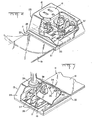
- Figures 4 and 5 are fragmentary perspective views of one end of a second example of extension cord with a cover of an outlet supporting housing omitted for clarity, showing the relative longitudinal positions of the shield and conductor strips in reeled and flat conditions of the cable, respectively.
- As shown particularly in Figures 1 to 3, the first example of extension cord comprises a predetermined length of undercarpet flat cable 11 mounted at opposite ends in rigid
insulating housings plug outlets - The undercarpet flat cable 11 comprises a
strip 16 of insulatedflat conductors 17 located in a stiffly flexible sleeve-form shield strip 18 comprising metal andplastics strips metal shield strip 21 is located in thesleeve 18 between theconductor strip 16 and theplastics strip 20. It should be noted that, thestrips sleeve 18 are free to move longitudinally relative to each other prior to termination of the cable. - The
outlet supporting housings planar base portions lip portions lip portions cable receiving mouths - As shown more particularly in Figure 3, one end of the undercarpet flat cable 11 is mounted in the
housing 13 by rivets orother fasteners 36 such as projections with heat deformed heads integral with thebase portion 26 and which pass through bothshield strips conductor strip 16 at locations between theconductors 17, fixing the cable strips relative to each other and to thehousing base 26. Theindividual conductors 17 are crimped to respective live and neutral leads of theplug outlet 15 byconventional terminals 37 having insulation-piercing arms which are curled back under the conductor strip into electrical engagement with the conductors. Atab terminal 38 held by a metal rivet passing through top andbottom shield strips 36 is connected by leads to the ground conductor of the cable 11 andplug outlet 15. Abush 39 secures the leads of theplug outlet 15 extending through an aperture in the top of thecover 24. - As shown more particularly in Figure 2, the other end of the undercarpet flat cable 11 is mounted in the duplex
socket supporting housing 12 byrivets 41 or other fasteners which pass throughinsulation 16 of the exposed conductor strip between theindividual conductors 17 thereby fixing the strip to thehousing base 25, whilst the sleeve-form shield 18 is received as a longitudinal sliding fit in themouth 33. Theindividual conductors 17 are also terminated by crimping to conventional terminals connected to leads extending to terminals of the conventionalduplex socket outlet 14. - Movement of the cable from the flat condition shown to a wound or reeled condition, indicated by broken lines, will cause the sleeve-
form shield strip 18 to slide longitudinally further into the housing to the position shown in broken lines. As theconductor strip 16 is fixed, no stress is imposed on the terminations whilst such sliding movement will permit the cable to lie flat when unwound or unreeled. Longitudinal movement of theshield strip 21 will also be accommodated. - In a second example of the invention, shown particularly in Figures 4 and 5, the cable 11 is terminated at one end as shown in Figure 3 and the sleeve-
form shield strip 18 is fixed at the other end to thebase 31 byrivets 46 or other fasteners.Flexible metal bands 47 which bow perpendicularly to the plane of theconductor strip 16 are clamped at one of the ends to respectiveflat conductors 17 byconventional terminals 48 which embrace the strip ends and are crimped around the conductors in a similar fashion toterminal 37, the other ends of the bands being crimped to respective socket outlet leads byconventional terminals 37 also crimped to aninsulating termination strip 48. - Movement of the cable from the wound or reeled condition of Figure 4 to the flat condition of Figure 5 will be
conductor strip 16 to slide longitudinally into the housing from the position shown in Figure 4 to the position shown in Figure 5, such movement being accommodated by increased bowing of thebands 47 without undue strain being imposed on the terminations. Un- bowing of thebands 47 will also permit the cable to be lie flat when unwound or unreeled. - It should be noted that any tendency for relative movement between the
metal strip 19 and theplastics strip 20 when changing the cable between wound and unwound conditions will be accommodated by longitudinal resilient compliance of the plastics strip without causing buckling of the cable.
Claims (5)
Applications Claiming Priority (2)
| Application Number | Priority Date | Filing Date | Title |
|---|---|---|---|
| US33955982A | 1982-01-15 | 1982-01-15 | |
| US339559 | 1982-01-15 |
Publications (3)
| Publication Number | Publication Date |
|---|---|
| EP0084258A2 EP0084258A2 (en) | 1983-07-27 |
| EP0084258A3 EP0084258A3 (en) | 1983-08-10 |
| EP0084258B1 true EP0084258B1 (en) | 1986-04-02 |
Family
ID=23329599
Family Applications (1)
| Application Number | Title | Priority Date | Filing Date |
|---|---|---|---|
| EP82306932A Expired EP0084258B1 (en) | 1982-01-15 | 1982-12-23 | End terminated, flat-cable assembly |
Country Status (5)
| Country | Link |
|---|---|
| EP (1) | EP0084258B1 (en) |
| JP (1) | JPS58123605A (en) |
| CA (1) | CA1192637A (en) |
| DE (1) | DE3270325D1 (en) |
| MX (1) | MX156813A (en) |
Families Citing this family (1)
| Publication number | Priority date | Publication date | Assignee | Title |
|---|---|---|---|---|
| JP3424785B2 (en) * | 1995-05-26 | 2003-07-07 | 矢崎総業株式会社 | Joint between flat cable and lead wire and method for forming the same |
Family Cites Families (4)
| Publication number | Priority date | Publication date | Assignee | Title |
|---|---|---|---|---|
| DE623765C (en) * | ||||
| DE1034732B (en) * | 1954-10-28 | 1958-07-24 | Kabelwerk Reinshagen G M B H | Flexible electrical line connection |
| US3524921A (en) * | 1968-06-07 | 1970-08-18 | Leo Wolf | Two-lead strip cable and sliding connector therefor |
| US4258974A (en) * | 1979-05-25 | 1981-03-31 | Thomas & Betts Corporation | Installation kit for undercarpet wiring system |
-
1982
- 1982-12-20 CA CA000418112A patent/CA1192637A/en not_active Expired
- 1982-12-23 DE DE8282306932T patent/DE3270325D1/en not_active Expired
- 1982-12-23 EP EP82306932A patent/EP0084258B1/en not_active Expired
-
1983
- 1983-01-14 JP JP58003617A patent/JPS58123605A/en active Pending
- 1983-01-14 MX MX195914A patent/MX156813A/en unknown
Also Published As
| Publication number | Publication date |
|---|---|
| MX156813A (en) | 1988-10-05 |
| JPS58123605A (en) | 1983-07-22 |
| CA1192637A (en) | 1985-08-27 |
| EP0084258A2 (en) | 1983-07-27 |
| DE3270325D1 (en) | 1986-05-07 |
| EP0084258A3 (en) | 1983-08-10 |
Similar Documents
| Publication | Publication Date | Title |
|---|---|---|
| US4780094A (en) | Extension cord of undercarpet flat cable | |
| US4171857A (en) | Cleat connector for insulated wires | |
| CA2094003C (en) | Cable strain relief for a shielded electrical connector | |
| JP3935878B2 (en) | Connector with improved grounding means | |
| GB2078450A (en) | A twin-contact terminal element | |
| US5288252A (en) | Flat-contact plug socket | |
| US5187887A (en) | Electric wire identifying tab and a band thereof | |
| EP0527399B1 (en) | Insulation displacement terminal | |
| JPH0626152B2 (en) | Shielded electrical plug assembly | |
| US3768062A (en) | Terminal for flexible circuits | |
| EP0136040A2 (en) | Round jacketed electrical cable | |
| EP0687037B1 (en) | Shielding arrangement between several shielding cables and a connector | |
| EP0084258A2 (en) | End terminated, flat-cable assembly | |
| GB2130820A (en) | Electrical contact for terminating insulated conductors | |
| US4927379A (en) | Electrical connector | |
| US4827228A (en) | In-line filtering device for a telecommunications line | |
| US4708664A (en) | Multipurpose boot for round-to-flat electrical cable | |
| US4564258A (en) | Preloaded electrical connector | |
| US5032084A (en) | Apparatus for providing an electrical conduction path between two contact locations which are rotatable with respect to each other | |
| JP7568488B2 (en) | Cable branch connection structure | |
| WO1995003644A1 (en) | Electrical distribution system | |
| JPH0511355U (en) | Device for fixing metal sleeves for cables | |
| AU2003262302A1 (en) | End-processing Structure of Flat Cable and Method of End-processing of Flat Cable | |
| JP3052177B2 (en) | Modular plug for LAN | |
| JPH0128952Y2 (en) |
Legal Events
| Date | Code | Title | Description |
|---|---|---|---|
| PUAI | Public reference made under article 153(3) epc to a published international application that has entered the european phase |
Free format text: ORIGINAL CODE: 0009012 |
|
| PUAL | Search report despatched |
Free format text: ORIGINAL CODE: 0009013 |
|
| AK | Designated contracting states |
Designated state(s): BE DE FR GB IT NL |
|
| AK | Designated contracting states |
Designated state(s): BE DE FR GB IT NL |
|
| 17P | Request for examination filed |
Effective date: 19830928 |
|
| ITF | It: translation for a ep patent filed | ||
| GRAA | (expected) grant |
Free format text: ORIGINAL CODE: 0009210 |
|
| AK | Designated contracting states |
Kind code of ref document: B1 Designated state(s): BE DE FR GB IT NL |
|
| REF | Corresponds to: |
Ref document number: 3270325 Country of ref document: DE Date of ref document: 19860507 |
|
| ET | Fr: translation filed | ||
| PLBE | No opposition filed within time limit |
Free format text: ORIGINAL CODE: 0009261 |
|
| STAA | Information on the status of an ep patent application or granted ep patent |
Free format text: STATUS: NO OPPOSITION FILED WITHIN TIME LIMIT |
|
| 26N | No opposition filed | ||
| ITTA | It: last paid annual fee | ||
| PGFP | Annual fee paid to national office [announced via postgrant information from national office to epo] |
Ref country code: FR Payment date: 19921108 Year of fee payment: 11 |
|
| PGFP | Annual fee paid to national office [announced via postgrant information from national office to epo] |
Ref country code: DE Payment date: 19921112 Year of fee payment: 11 |
|
| PGFP | Annual fee paid to national office [announced via postgrant information from national office to epo] |
Ref country code: GB Payment date: 19921119 Year of fee payment: 11 |
|
| PGFP | Annual fee paid to national office [announced via postgrant information from national office to epo] |
Ref country code: BE Payment date: 19921126 Year of fee payment: 11 |
|
| PG25 | Lapsed in a contracting state [announced via postgrant information from national office to epo] |
Ref country code: GB Effective date: 19931223 |
|
| PG25 | Lapsed in a contracting state [announced via postgrant information from national office to epo] |
Ref country code: BE Effective date: 19931231 |
|
| REG | Reference to a national code |
Ref country code: GB Ref legal event code: 732E |
|
| BERE | Be: lapsed |
Owner name: AMP INC. (UNE SOC. DE PENNSYLVANIE) Effective date: 19931231 |
|
| GBPC | Gb: european patent ceased through non-payment of renewal fee |
Effective date: 19931223 |
|
| PG25 | Lapsed in a contracting state [announced via postgrant information from national office to epo] |
Ref country code: FR Effective date: 19940831 |
|
| PG25 | Lapsed in a contracting state [announced via postgrant information from national office to epo] |
Ref country code: DE Effective date: 19940901 |
|
| REG | Reference to a national code |
Ref country code: FR Ref legal event code: ST |
|
| PGFP | Annual fee paid to national office [announced via postgrant information from national office to epo] |
Ref country code: NL Payment date: 19960924 Year of fee payment: 15 |
|
| PG25 | Lapsed in a contracting state [announced via postgrant information from national office to epo] |
Ref country code: NL Free format text: LAPSE BECAUSE OF NON-PAYMENT OF DUE FEES Effective date: 19980701 |
|
| NLV4 | Nl: lapsed or anulled due to non-payment of the annual fee |
Effective date: 19980701 |