EP0082553B1 - Bifunctional gas diffusion electrode - Google Patents
Bifunctional gas diffusion electrode Download PDFInfo
- Publication number
- EP0082553B1 EP0082553B1 EP82201564A EP82201564A EP0082553B1 EP 0082553 B1 EP0082553 B1 EP 0082553B1 EP 82201564 A EP82201564 A EP 82201564A EP 82201564 A EP82201564 A EP 82201564A EP 0082553 B1 EP0082553 B1 EP 0082553B1
- Authority
- EP
- European Patent Office
- Prior art keywords
- gas
- layer
- side layer
- electrolyte
- electrode
- Prior art date
- Legal status (The legal status is an assumption and is not a legal conclusion. Google has not performed a legal analysis and makes no representation as to the accuracy of the status listed.)
- Expired
Links
Images
Classifications
-
- H—ELECTRICITY
- H01—ELECTRIC ELEMENTS
- H01M—PROCESSES OR MEANS, e.g. BATTERIES, FOR THE DIRECT CONVERSION OF CHEMICAL ENERGY INTO ELECTRICAL ENERGY
- H01M4/00—Electrodes
- H01M4/86—Inert electrodes with catalytic activity, e.g. for fuel cells
- H01M4/8605—Porous electrodes
- H01M4/8615—Bifunctional electrodes for rechargeable cells
-
- H—ELECTRICITY
- H01—ELECTRIC ELEMENTS
- H01M—PROCESSES OR MEANS, e.g. BATTERIES, FOR THE DIRECT CONVERSION OF CHEMICAL ENERGY INTO ELECTRICAL ENERGY
- H01M10/00—Secondary cells; Manufacture thereof
- H01M10/34—Gastight accumulators
- H01M10/345—Gastight metal hydride accumulators
-
- H—ELECTRICITY
- H01—ELECTRIC ELEMENTS
- H01M—PROCESSES OR MEANS, e.g. BATTERIES, FOR THE DIRECT CONVERSION OF CHEMICAL ENERGY INTO ELECTRICAL ENERGY
- H01M12/00—Hybrid cells; Manufacture thereof
- H01M12/08—Hybrid cells; Manufacture thereof composed of a half-cell of a fuel-cell type and a half-cell of the secondary-cell type
-
- Y—GENERAL TAGGING OF NEW TECHNOLOGICAL DEVELOPMENTS; GENERAL TAGGING OF CROSS-SECTIONAL TECHNOLOGIES SPANNING OVER SEVERAL SECTIONS OF THE IPC; TECHNICAL SUBJECTS COVERED BY FORMER USPC CROSS-REFERENCE ART COLLECTIONS [XRACs] AND DIGESTS
- Y02—TECHNOLOGIES OR APPLICATIONS FOR MITIGATION OR ADAPTATION AGAINST CLIMATE CHANGE
- Y02E—REDUCTION OF GREENHOUSE GAS [GHG] EMISSIONS, RELATED TO ENERGY GENERATION, TRANSMISSION OR DISTRIBUTION
- Y02E60/00—Enabling technologies; Technologies with a potential or indirect contribution to GHG emissions mitigation
- Y02E60/10—Energy storage using batteries
Definitions
- the invention relates to bifunctional gas diffusion electrodes operative alternately for gas consumption and gas evolution, and to secondary metal-gas batteries incorporating such electrodes.
- gas diffusion electrode a porous catalytic electrode in which a gas reactant and an aqueous electrolyte are brought into contact to react electrochemically.
- Gas diffusion electrodes are used extensively in electrochemical power sources such as metal-air and metal-hydrogen batteries or fuel cells. In all of these, the gas diffusion electrode is on one side in contact with an electrolyte and on the other side in contact with a gas. In the metal-air battery the gas is air.
- bi-functional gas diffusion electrodes which operate alternately for gas consumption and gas evolution. These electrodes, which combine cathodic and anodic functions, are known as bi-functional gas diffusion electrodes.
- a typical application of these bifunctional electrodes is in secondary metal-gas batteries such as iron-air, zinc-air and nickel- hydrogen batteries which consume gas during discharge and evolve gas during electrical recharging.
- German Patent Application DT 19 21 157 describes a rechargeable metal-air battery with a bifunctional gas diffusion electrode comprising two electrode layers bonded to each other: a hydrophilic electrolyte-side layer made of porous nickel and a hydrophobic gas-side layer made of carbon, PTFE binder and preferably impregnated with an oxygen-reducing catalyst.
- the hydrophilic porous nickel layer has a dual function, as a current collector and as an active layer for oxygen evolution during charge.
- the gas-side hydrophobic layer is an active area of the electrode during the gas consumption phase or discharge cycle of the battery.
- the invention is directed to novel composite bifunctional gas diffusion electrodes and to secondary metal-gas batteries incorporating such electrodes, as set out in the claims, in which the problem of unwanted gas evolution in the gas-side layer is greatly reduced by providing an intermediate rectifying layer of semi-conducting material.
- This semi-conducting layer may be a p-n junction diode or may contact a layer of metal to form a Shottky barrier junction.
- This rectifier is always arranged in such a way that the gas-side layer is practically electrically inactive during the gas evolution phase which corresponds to the charging cycle of the battery, so that substantially no undesired gas evolution can take place in this layer. Electrode flow into or out of the gas-side layer of the electrode is thus allowed freely during the gas consumption phase which corresponds to discharge of the battery, but is strongly inhibited during charging.
- the arrangement of the rectifying layer to provide the desired direction of electron flow depends on the nature of the gas reactant used, i.e. whether the gas is reduced or is oxidised during the consumption phase.
- the supplied gas When the supplied gas is reduced, electrons must be able to flow into the gas-side layer and when the supplied gas is oxidised, electrons must be able to flow out of the gas-side layer.
- the p-type conducting zone will face the gas-side layer and the n-type conducting zone will face the electrolyte-side layer.
- the rectifying semi-conducting layer is a porous electrolyte permeable layer formed, for example, of appropriately doped materials such as Te, SbBi, Sb, Si, GeTe, Ge, Bi, InAs, InSb, CdSnAs 2 , GaSb and Bi 2 Te 3 .
- the current collection means is a foraminate metal current collector of sandwich construction in which the semi- conducting layer is encapsulated, and hence protected from the electrolyte.
- the semi-conducting layer is sandwiched between two foraminous sheets of nickel foil.
- the outer part of this current collector can constitute the gas-evolving part of the electrolyte-side layer of the bifunctional electrode.
- the rectifying layer it is desirable but not essential for the rectifying layer to occupy the entire surface of the electrode.
- an array of small rectifying layers can be placed between the gas-side layer and the electrolyte-side layer.
- the bifunctional gas-diffusion electrode of the invention is useful in other systems involving alternate gas evolution and consumption, for example as oxygen cathodes in chlor-alkali electrolysis where gas evolution within the gas-diffusion electrode structure must be avoided. Such unwanted gas evolution can happen when the cells are shortcircuited for maintenance.
- a metal-gas battery comprises a metal electrode 1, using iron, zinc, cadmium, or nickel oxide as active material; an electrolyte compartment 2, containing an alkali hydroxide electrolyte, preferably KOH; and a bifunctional gas diffusion electrode 3.
- the bifunctional electrode 3 of the present invention comprises a porous carbon hydrophilic electrolyte-side layer 4 and a hydrophobic gas side-layer 6, separated by a porous semi-conducting layer 7.
- the hydrophilic porous electrolyte-side layer 4 contains a pressed-in current collector 5, preferable a foraminous nickel plate or mesh.
- the hydrophobic gas-side layer 6 has a catalytically- active gas reaction zone 6a made of pressed carbon particles impregnated with silver, platinum or another catalyst and a binder preferably PTFE, and a hydrophobic backing 6b directly exposed to a reacting gas, e.g. air/oxygen.
- a reacting gas e.g. air/oxygen.
- the part of zone 6a adjacent the semi-conducting layer 7 is sufficiently hydrophilic to be impregnated with electrolyte penetrating via layer 7 to set up a 3-phase reaction boundary within the generally hydrophobic reaction zone 6a.
- the semi-conducting layer 7 is made of a semi- conductor such as germanium or silicon, doped by conventional techniques to provide a p-n junction diode. As shown, this diode is arranged to allow electron flow from layer 4 to layer 6 but not in the reverse direction.
- the .layer 7 consists of a wafer of n-type germanium doped with indium to form a p-type conducting zone on its face adjacent the gas-side layer 6.
- the forward voltage bias or conduction of the layer is preferably no greater than about 0.1 V.
- the battery is charged by an external charger 9 and discharged via external load 8.
- a potential difference is applied between the metal electrode 1 and current collector 5 by means of charger 9 so that electrons flow from electrolyte-side layer 4 of the gas diffusion electrode through the charger 9 to metal electrode 1.
- gas evolution takes place on the electrolyte-side 4 of the gas diffusion electrode which acts as anode; however, virtually no gas evolution can take place within the gas-side layer 6 because of the rectifying effect of the semi- conducting layer 7.
- electrons flow from the metal electrode 1 through the load 8 and current collector 5 and through the semi-conductor layer 7 into the gas side of the bifunctional electrode where a reduction reaction with a supplied gas takes place in zone 6a.
- the battery may conveniently be operated above room temperature.
- FIG. 2 shows a bifunctional electrode 20 comprising a composite current collector 21, a gas-side layer 22, e.g. of porous carbon impregnated with a catalyst, and a hydrophobic back layer 23.
- the current collector 21 comprises two foraminous sheets 24, 25 of corrosion-resistant metal, preferably nickel or a nickel-silver alloy, between which a semiconductor layer 26 is sandwiched with a protective layer of electrically insulating material 27 applied over the exposed edges so that the semi-conductor layer 26 is encapsulated.
- the semi-conductor material is thus protected from chemical attack when the electrode is in its operating environment with an electrolyte such as KOH on the side of the current collector 21 and a gas supplied to the gas-side layer 22 via the backing 23.
- the outer sheet 24 of the current collector thus forms the operative gas-evolving face of the bifunctional electrode.
- sheet 24 can be coated with an electrocatalytic gas-evolution coating such as one or more platinum-group metal oxides, mixed platinum-group metal oxide valve metal oxides, or other mixed oxides such as spinels and perovskites.
- an electrocatalytic gas-evolution coating such as one or more platinum-group metal oxides, mixed platinum-group metal oxide valve metal oxides, or other mixed oxides such as spinels and perovskites.
- the surface of sheet 25 facing the gas-side layer can be coated with silver or another coating which reduces corrosion contact between the current collector and the carbon of layer 22.
- the outer sheet 24 is connected to a metal electrode of a battery via an external charger or a load and thus effectively acts as current collector whereas the rear sheet 25 simply acts as a backing and to conduct current into or out of the gas-side layer during discharge of the battery.
- the semi-conducting layer 26 acts as a rectifier to prevent the flow of current into or out of layer 22 during charging of the battery thereby preventing unwanted gas evolution therein.
- the layer 26 may be formed of any of the aforementioned semi-conducting materials.
- the rectifying effect may be produced either by making the layer 26 form a p-n junction diode, or by making the layer 26 of p or n-type semi-conducting material which forms a Schottky barrier junction with one of the metal sheets 24 or 25 and an ohmic contact with the other one.
- the layer 26 should have a low contact resistance with the nickel or other sheets 24, 25 and this can be ensured by vapour deposition of a thin metal layer on the semi-conductor prior to lamination of the sandwich assembly.
- a Schottky barrier junction can conveniently be formed with two nickel sheets 24, 25 in contact with an n-doped layer having one surface heavily doped n + , a rectifying Schottky junction being formed at the interface of the n-doped region and one nickel sheet, and a non-rectifying ohmic contact being formed at the interface of the n + doped region and other nickel sheet.
Landscapes
- Chemical & Material Sciences (AREA)
- Chemical Kinetics & Catalysis (AREA)
- Electrochemistry (AREA)
- General Chemical & Material Sciences (AREA)
- Engineering & Computer Science (AREA)
- Manufacturing & Machinery (AREA)
- Inert Electrodes (AREA)
- Hybrid Cells (AREA)
- Electrodes Of Semiconductors (AREA)
Abstract
Description
- The invention relates to bifunctional gas diffusion electrodes operative alternately for gas consumption and gas evolution, and to secondary metal-gas batteries incorporating such electrodes.
- By gas diffusion electrode is understood a porous catalytic electrode in which a gas reactant and an aqueous electrolyte are brought into contact to react electrochemically. Gas diffusion electrodes are used extensively in electrochemical power sources such as metal-air and metal-hydrogen batteries or fuel cells. In all of these, the gas diffusion electrode is on one side in contact with an electrolyte and on the other side in contact with a gas. In the metal-air battery the gas is air.
- Attempts have already been made to provide gas diffusion electrodes which operate alternately for gas consumption and gas evolution. These electrodes, which combine cathodic and anodic functions, are known as bi-functional gas diffusion electrodes. A typical application of these bifunctional electrodes is in secondary metal-gas batteries such as iron-air, zinc-air and nickel- hydrogen batteries which consume gas during discharge and evolve gas during electrical recharging.
- German Patent Application DT 19 21 157 describes a rechargeable metal-air battery with a bifunctional gas diffusion electrode comprising two electrode layers bonded to each other: a hydrophilic electrolyte-side layer made of porous nickel and a hydrophobic gas-side layer made of carbon, PTFE binder and preferably impregnated with an oxygen-reducing catalyst. The hydrophilic porous nickel layer has a dual function, as a current collector and as an active layer for oxygen evolution during charge. The gas-side hydrophobic layer is an active area of the electrode during the gas consumption phase or discharge cycle of the battery. Thus, the two active zones of the electrode during charge and discharge were theoretically kept apart, but some unwanted oxygen evolution took place in the hydrophobic gas-side layer during charge and, despite attempts to prevent this by an increase of pressure on the gas-side of the electrode, was the cause of corrosion, deactivation of the catalyst and a reduced lifetime.
- Efforts to improve these bifunctional electrodes, in particular to obtain an acceptable lifetime, have not been successful to date with the result that metal-gas batteries still have a relatively limited use.
- The invention is directed to novel composite bifunctional gas diffusion electrodes and to secondary metal-gas batteries incorporating such electrodes, as set out in the claims, in which the problem of unwanted gas evolution in the gas-side layer is greatly reduced by providing an intermediate rectifying layer of semi-conducting material. This semi-conducting layer may be a p-n junction diode or may contact a layer of metal to form a Shottky barrier junction. This rectifier is always arranged in such a way that the gas-side layer is practically electrically inactive during the gas evolution phase which corresponds to the charging cycle of the battery, so that substantially no undesired gas evolution can take place in this layer. Electrode flow into or out of the gas-side layer of the electrode is thus allowed freely during the gas consumption phase which corresponds to discharge of the battery, but is strongly inhibited during charging.
- The arrangement of the rectifying layer to provide the desired direction of electron flow depends on the nature of the gas reactant used, i.e. whether the gas is reduced or is oxidised during the consumption phase. When the supplied gas is reduced, electrons must be able to flow into the gas-side layer and when the supplied gas is oxidised, electrons must be able to flow out of the gas-side layer. To illustrate this, in the case of a p-n junction used in a metal-air battery (i.e. where gas reduction takes place), the p-type conducting zone will face the gas-side layer and the n-type conducting zone will face the electrolyte-side layer. Conversely, in the case of gas oxidation (as in metal-hydrogen batteries), the relative position of the two zones will be reversed, the n-type semi-conducting zone facing the gas-side and the p-type semi-conducting zone facing the electrolyte-side of the bifunctional electrode.
- In one embodiment of the invention, the rectifying semi-conducting layer is a porous electrolyte permeable layer formed, for example, of appropriately doped materials such as Te, SbBi, Sb, Si, GeTe, Ge, Bi, InAs, InSb, CdSnAs2, GaSb and Bi2Te3.
- In a preferred embodiment, the current collection means is a foraminate metal current collector of sandwich construction in which the semi- conducting layer is encapsulated, and hence protected from the electrolyte. For example, the semi-conducting layer is sandwiched between two foraminous sheets of nickel foil. The outer part of this current collector can constitute the gas-evolving part of the electrolyte-side layer of the bifunctional electrode.
- It is desirable but not essential for the rectifying layer to occupy the entire surface of the electrode. Conveniently, and especially for large electrode, an array of small rectifying layers can be placed between the gas-side layer and the electrolyte-side layer.
- Although the invention is described with specific reference to use of the electrodes in batteries, especially metal-gas batteries, the bifunctional gas-diffusion electrode of the invention is useful in other systems involving alternate gas evolution and consumption, for example as oxygen cathodes in chlor-alkali electrolysis where gas evolution within the gas-diffusion electrode structure must be avoided. Such unwanted gas evolution can happen when the cells are shortcircuited for maintenance.
-
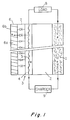
- Figure 1 is a schematic cross-section of one metal-gas battery module with a bifunctional gas diffusion electrode according to this invention.
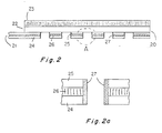
- Figure 2 is a schematic cross-section of another bifunctional gas diffusion electrode with a composite current collector of the present invention.
- Figure 2A shows a detail of the composite current collector of Figure 2.
- As shown in Fig. 1, a metal-gas battery comprises a metal electrode 1, using iron, zinc, cadmium, or nickel oxide as active material; an
electrolyte compartment 2, containing an alkali hydroxide electrolyte, preferably KOH; and a bifunctionalgas diffusion electrode 3. Thebifunctional electrode 3 of the present invention comprises a porous carbon hydrophilic electrolyte-side layer 4 and a hydrophobic gas side-layer 6, separated by a porous semi-conducting layer 7. The hydrophilic porous electrolyte-side layer 4 contains a pressed-in current collector 5, preferable a foraminous nickel plate or mesh. The hydrophobic gas-side layer 6 has a catalytically- activegas reaction zone 6a made of pressed carbon particles impregnated with silver, platinum or another catalyst and a binder preferably PTFE, and ahydrophobic backing 6b directly exposed to a reacting gas, e.g. air/oxygen. The part ofzone 6a adjacent the semi-conducting layer 7 is sufficiently hydrophilic to be impregnated with electrolyte penetrating via layer 7 to set up a 3-phase reaction boundary within the generallyhydrophobic reaction zone 6a. - The semi-conducting layer 7 is made of a semi- conductor such as germanium or silicon, doped by conventional techniques to provide a p-n junction diode. As shown, this diode is arranged to allow electron flow from
layer 4 to layer 6 but not in the reverse direction. For example, the .layer 7 consists of a wafer of n-type germanium doped with indium to form a p-type conducting zone on its face adjacent the gas-side layer 6. The forward voltage bias or conduction of the layer is preferably no greater than about 0.1 V. - Multiples of the module shown in Figure 1 constitute a metal-gas battery of any desired capacity.
- The battery is charged by an
external charger 9 and discharged viaexternal load 8. To charge the battery a potential difference is applied between the metal electrode 1 and current collector 5 by means ofcharger 9 so that electrons flow from electrolyte-side layer 4 of the gas diffusion electrode through thecharger 9 to metal electrode 1. During charging, gas evolution takes place on the electrolyte-side 4 of the gas diffusion electrode which acts as anode; however, virtually no gas evolution can take place within the gas-side layer 6 because of the rectifying effect of the semi- conducting layer 7. Conversely, when discharging the battery, electrons flow from the metal electrode 1 through theload 8 and current collector 5 and through the semi-conductor layer 7 into the gas side of the bifunctional electrode where a reduction reaction with a supplied gas takes place inzone 6a. - To minimize the forward bias voltage of the rectifying semi-conducting layer 7, the battery may conveniently be operated above room temperature.
- Figure 2 shows a
bifunctional electrode 20 comprising a compositecurrent collector 21, a gas-side layer 22, e.g. of porous carbon impregnated with a catalyst, and ahydrophobic back layer 23. Thecurrent collector 21 comprises twoforaminous sheets semiconductor layer 26 is sandwiched with a protective layer of electrically insulatingmaterial 27 applied over the exposed edges so that thesemi-conductor layer 26 is encapsulated. The semi-conductor material is thus protected from chemical attack when the electrode is in its operating environment with an electrolyte such as KOH on the side of thecurrent collector 21 and a gas supplied to the gas-side layer 22 via thebacking 23. Theouter sheet 24 of the current collector thus forms the operative gas-evolving face of the bifunctional electrode. If desired, to reduce energy requirements during charging of the battery,sheet 24 can be coated with an electrocatalytic gas-evolution coating such as one or more platinum-group metal oxides, mixed platinum-group metal oxide valve metal oxides, or other mixed oxides such as spinels and perovskites. Also, if desired, the surface ofsheet 25 facing the gas-side layer can be coated with silver or another coating which reduces corrosion contact between the current collector and the carbon oflayer 22. - The
outer sheet 24 is connected to a metal electrode of a battery via an external charger or a load and thus effectively acts as current collector whereas therear sheet 25 simply acts as a backing and to conduct current into or out of the gas-side layer during discharge of the battery. - As before, the
semi-conducting layer 26 acts as a rectifier to prevent the flow of current into or out oflayer 22 during charging of the battery thereby preventing unwanted gas evolution therein. Thelayer 26 may be formed of any of the aforementioned semi-conducting materials. The rectifying effect may be produced either by making thelayer 26 form a p-n junction diode, or by making thelayer 26 of p or n-type semi-conducting material which forms a Schottky barrier junction with one of themetal sheets layer 26 should have a low contact resistance with the nickel orother sheets nickel sheets
Claims (11)
Priority Applications (1)
| Application Number | Priority Date | Filing Date | Title |
|---|---|---|---|
| AT82201564T ATE29089T1 (en) | 1981-12-21 | 1982-12-09 | BIFUNCTIONAL GAS DIFFUSION ELECTRODE. |
Applications Claiming Priority (2)
| Application Number | Priority Date | Filing Date | Title |
|---|---|---|---|
| US332519 | 1981-12-21 | ||
| US06/332,519 US4409301A (en) | 1981-12-21 | 1981-12-21 | Bifunctional gas diffusion electrode |
Publications (3)
| Publication Number | Publication Date |
|---|---|
| EP0082553A2 EP0082553A2 (en) | 1983-06-29 |
| EP0082553A3 EP0082553A3 (en) | 1985-07-17 |
| EP0082553B1 true EP0082553B1 (en) | 1987-08-19 |
Family
ID=23298585
Family Applications (1)
| Application Number | Title | Priority Date | Filing Date |
|---|---|---|---|
| EP82201564A Expired EP0082553B1 (en) | 1981-12-21 | 1982-12-09 | Bifunctional gas diffusion electrode |
Country Status (6)
| Country | Link |
|---|---|
| US (1) | US4409301A (en) |
| EP (1) | EP0082553B1 (en) |
| JP (1) | JPS58111269A (en) |
| AT (1) | ATE29089T1 (en) |
| CA (1) | CA1195377A (en) |
| DE (1) | DE3277049D1 (en) |
Families Citing this family (6)
| Publication number | Priority date | Publication date | Assignee | Title |
|---|---|---|---|---|
| SE461820B (en) * | 1987-08-10 | 1990-03-26 | Ts Lab Elektrochimicheski Izto | DEVICE AND ACID RECOVERY IN LEAD BATTERIES |
| US5306579A (en) * | 1992-10-30 | 1994-04-26 | Aer Energy Resources, Inc. | Bifunctional metal-air electrode |
| US5318862A (en) * | 1993-09-22 | 1994-06-07 | Westinghouse Electric Corp. | Bifunctional gas diffusion electrodes employing wettable, non-wettable layered structure using the mud-caking concept |
| EP1843415A1 (en) * | 2006-04-06 | 2007-10-10 | Vlaamse Instelling Voor Technologisch Onderzoek (Vito) | Bifunctional gas diffusion electrodes |
| CA2824007C (en) * | 2011-02-04 | 2019-02-19 | Afc Energy Plc | Fuel cell electrodes |
| WO2012111101A1 (en) * | 2011-02-16 | 2012-08-23 | 富士通株式会社 | Air secondary battery |
Family Cites Families (8)
| Publication number | Priority date | Publication date | Assignee | Title |
|---|---|---|---|---|
| US3400305A (en) * | 1964-08-18 | 1968-09-03 | Audrey Dinwiddie Coffman | Alternating current electrodes for electrochemical power cells |
| US3898103A (en) * | 1969-03-21 | 1975-08-05 | Electrochem Inc | Semi-conductor electrode depolarizer |
| FR2085867A1 (en) * | 1970-04-06 | 1971-12-31 | Leesona Corp | Rechargeable metal/air or metal-oxygencells |
| FR2102480A5 (en) * | 1970-08-05 | 1972-04-07 | Comp Generale Electricite | Fuel electrode for metal-air/oxygen cell - having second porous layer for disengaging oxygen |
| DE2057446C3 (en) * | 1970-11-23 | 1981-11-26 | Deutsche Automobilgesellschaft Mbh, 7000 Stuttgart | Reversible air electrode for metal-air elements with a rechargeable negative electrode |
| US4007059A (en) * | 1975-08-20 | 1977-02-08 | General Motors Corporation | Electrochemical cell electrode separator and method of making it and fuel cell containing same |
| US4333993A (en) * | 1980-09-22 | 1982-06-08 | Gould Inc. | Air cathode for air depolarized cells |
| US4341848A (en) * | 1981-03-05 | 1982-07-27 | The United States Of America As Represented By The United States Department Of Energy | Bifunctional air electrodes containing elemental iron powder charging additive |
-
1981
- 1981-12-21 US US06/332,519 patent/US4409301A/en not_active Expired - Fee Related
-
1982
- 1982-11-24 CA CA000416239A patent/CA1195377A/en not_active Expired
- 1982-12-09 DE DE8282201564T patent/DE3277049D1/en not_active Expired
- 1982-12-09 AT AT82201564T patent/ATE29089T1/en not_active IP Right Cessation
- 1982-12-09 EP EP82201564A patent/EP0082553B1/en not_active Expired
- 1982-12-20 JP JP57223636A patent/JPS58111269A/en active Granted
Also Published As
| Publication number | Publication date |
|---|---|
| EP0082553A3 (en) | 1985-07-17 |
| DE3277049D1 (en) | 1987-09-24 |
| US4409301A (en) | 1983-10-11 |
| JPS58111269A (en) | 1983-07-02 |
| CA1195377A (en) | 1985-10-15 |
| JPH0139634B2 (en) | 1989-08-22 |
| ATE29089T1 (en) | 1987-09-15 |
| EP0082553A2 (en) | 1983-06-29 |
Similar Documents
| Publication | Publication Date | Title |
|---|---|---|
| EP0667041B1 (en) | Bifunctional airelectrode | |
| US5069988A (en) | Metal and metal oxide catalyzed electrodes for electrochemical cells, and methods of making same | |
| US3432354A (en) | Electrochemical power supply with movable anode material | |
| US6998184B2 (en) | Hybrid fuel cell | |
| US7344801B2 (en) | High-voltage dual electrolyte electrochemical power sources | |
| US3438812A (en) | Rechargeable alkaline cell | |
| US4053685A (en) | End-reacting electrochemical battery | |
| US7435492B2 (en) | Hybrid fuel cell | |
| WO2019151063A1 (en) | Negative electrode for metal air cell | |
| US7220501B2 (en) | Integrated hybrid electrochemical device | |
| US4057675A (en) | Electrochemical cell | |
| EP0082553B1 (en) | Bifunctional gas diffusion electrode | |
| EP2001072A2 (en) | Powdered Fuel Cell | |
| AU549585B2 (en) | Sealed nickel-zinc battery | |
| EP2909880B1 (en) | Electrochemical cell with doping of metallic anodes | |
| US3479226A (en) | Method of chemically regenerating air depolarized cell with hydrogen | |
| EP0533711A1 (en) | Metal and metal oxide catalyzed electrodes for electrochemical cells, and methods of making same | |
| US3446675A (en) | Electrochemical power supply | |
| US7906246B2 (en) | Powdered fuel cell | |
| JP3196151B2 (en) | Light air secondary battery | |
| US20220013864A1 (en) | Metal-air battery | |
| Jörissen et al. | Applications of Bifunctional Air Electrodes | |
| Hine | Batteries |
Legal Events
| Date | Code | Title | Description |
|---|---|---|---|
| PUAI | Public reference made under article 153(3) epc to a published international application that has entered the european phase |
Free format text: ORIGINAL CODE: 0009012 |
|
| AK | Designated contracting states |
Designated state(s): AT BE CH DE FR GB IT LI LU NL SE |
|
| RAP1 | Party data changed (applicant data changed or rights of an application transferred) |
Owner name: ELTECH SYSTEMS CORPORATION |
|
| PUAL | Search report despatched |
Free format text: ORIGINAL CODE: 0009013 |
|
| AK | Designated contracting states |
Designated state(s): AT BE CH DE FR GB IT LI LU NL SE |
|
| 17P | Request for examination filed |
Effective date: 19850607 |
|
| 17Q | First examination report despatched |
Effective date: 19861021 |
|
| ITF | It: translation for a ep patent filed | ||
| GRAA | (expected) grant |
Free format text: ORIGINAL CODE: 0009210 |
|
| AK | Designated contracting states |
Kind code of ref document: B1 Designated state(s): AT BE CH DE FR GB IT LI LU NL SE |
|
| PG25 | Lapsed in a contracting state [announced via postgrant information from national office to epo] |
Ref country code: NL Effective date: 19870819 Ref country code: LI Effective date: 19870819 Ref country code: CH Effective date: 19870819 Ref country code: BE Effective date: 19870819 Ref country code: AT Effective date: 19870819 |
|
| REF | Corresponds to: |
Ref document number: 29089 Country of ref document: AT Date of ref document: 19870915 Kind code of ref document: T |
|
| PG25 | Lapsed in a contracting state [announced via postgrant information from national office to epo] |
Ref country code: SE Effective date: 19870831 |
|
| REF | Corresponds to: |
Ref document number: 3277049 Country of ref document: DE Date of ref document: 19870924 |
|
| ET | Fr: translation filed | ||
| REG | Reference to a national code |
Ref country code: CH Ref legal event code: PL |
|
| PG25 | Lapsed in a contracting state [announced via postgrant information from national office to epo] |
Ref country code: LU Free format text: LAPSE BECAUSE OF NON-PAYMENT OF DUE FEES Effective date: 19871231 |
|
| NLV1 | Nl: lapsed or annulled due to failure to fulfill the requirements of art. 29p and 29m of the patents act | ||
| PLBE | No opposition filed within time limit |
Free format text: ORIGINAL CODE: 0009261 |
|
| STAA | Information on the status of an ep patent application or granted ep patent |
Free format text: STATUS: NO OPPOSITION FILED WITHIN TIME LIMIT |
|
| 26N | No opposition filed | ||
| PGFP | Annual fee paid to national office [announced via postgrant information from national office to epo] |
Ref country code: DE Payment date: 19881222 Year of fee payment: 7 |
|
| ITTA | It: last paid annual fee | ||
| PG25 | Lapsed in a contracting state [announced via postgrant information from national office to epo] |
Ref country code: GB Effective date: 19891209 |
|
| GBPC | Gb: european patent ceased through non-payment of renewal fee | ||
| PG25 | Lapsed in a contracting state [announced via postgrant information from national office to epo] |
Ref country code: FR Effective date: 19900831 |
|
| PG25 | Lapsed in a contracting state [announced via postgrant information from national office to epo] |
Ref country code: DE Effective date: 19900901 |
|
| REG | Reference to a national code |
Ref country code: FR Ref legal event code: ST |