EP0082129A1 - Device for storing, transporting and conveying cylindrical articles - Google Patents
Device for storing, transporting and conveying cylindrical articles Download PDFInfo
- Publication number
- EP0082129A1 EP0082129A1 EP82870070A EP82870070A EP0082129A1 EP 0082129 A1 EP0082129 A1 EP 0082129A1 EP 82870070 A EP82870070 A EP 82870070A EP 82870070 A EP82870070 A EP 82870070A EP 0082129 A1 EP0082129 A1 EP 0082129A1
- Authority
- EP
- European Patent Office
- Prior art keywords
- raceway
- frame
- objects
- orifice
- outlet
- Prior art date
- Legal status (The legal status is an assumption and is not a legal conclusion. Google has not performed a legal analysis and makes no representation as to the accuracy of the status listed.)
- Withdrawn
Links
Images


Classifications
-
- B—PERFORMING OPERATIONS; TRANSPORTING
- B65—CONVEYING; PACKING; STORING; HANDLING THIN OR FILAMENTARY MATERIAL
- B65G—TRANSPORT OR STORAGE DEVICES, e.g. CONVEYORS FOR LOADING OR TIPPING, SHOP CONVEYOR SYSTEMS OR PNEUMATIC TUBE CONVEYORS
- B65G1/00—Storing articles, individually or in orderly arrangement, in warehouses or magazines
- B65G1/02—Storage devices
- B65G1/04—Storage devices mechanical
- B65G1/06—Storage devices mechanical with means for presenting articles for removal at predetermined position or level
- B65G1/08—Storage devices mechanical with means for presenting articles for removal at predetermined position or level the articles being fed by gravity
-
- B—PERFORMING OPERATIONS; TRANSPORTING
- B60—VEHICLES IN GENERAL
- B60P—VEHICLES ADAPTED FOR LOAD TRANSPORTATION OR TO TRANSPORT, TO CARRY, OR TO COMPRISE SPECIAL LOADS OR OBJECTS
- B60P7/00—Securing or covering of load on vehicles
- B60P7/06—Securing of load
- B60P7/08—Securing to the vehicle floor or sides
- B60P7/12—Securing to the vehicle floor or sides the load being tree-trunks, beams, drums, tubes, or the like
Definitions
- the present invention relates to a device for the storage, transport and handling of heavy cylindrical objects of the same dimensions, in particular drums, carboys, etc.
- the barrels, carboys, etc. are generally arranged, for reasons of stability, so as to rest on one of their bases.
- a stowage for example using dropsides, of a group of drums arranged on a level.
- the stowage problems are very difficult to solve and the stowage that can be carried out, if they can withstand ideal conditions of transport, is well often unreliable during incidents, such as sudden braking, shocks caused by defective tracks, etc., or traffic accidents and can pose serious risks, by the means of transport used and surrounding it, by collapse and dispersal of the cargo.
- loading and unloading drums especially when it is manual, is not only very painful but is often the cause of accidents.
- the invention aims to remedy these drawbacks and to provide a device in which the drums, carboys, etc. are stored so that their axis is substantially horizontal.
- the drums contained in this device have the advantage of being perfectly immobilized with respect to each other so that, when devices are placed, for transporting the drums, on the loading platform of a transport vehicle, it do not worry about the individual stowage of the drums but only the stowage of the devices containing the drums.
- each of the devices according to the invention contains a large number of drums, this securing of the devices on the transport unit is not even necessary since they are sufficiently stable thanks to their weight and, otherwise, this stowage is, according to the invention, easy, fast and free from any risk.
- the above-mentioned device or devices can also be permanently fixed to the transport vehicle, which makes it possible, in this case, to eliminate all operations for securing the drums and the devices that contain them.
- the device according to the invention has the enormous advantage of considerably simplifying the loading and unloading operations of the drums by eliminating the movement and positioning of each of the drums, these being on the one hand , inserted into each of the devices, in a fixed location that is well defined and easily accessible, to automatically place themselves in the desired position and, on the other hand, extracted from the device either one by one, or in series, in another fixed place, well determined and easily accessible, next to which the barrels appear automatically.
- the device according to the invention also has the advantage of being light enough compared to the drums it contains and of a sufficiently small footprint not to significantly reduce the transport capacity in drums of the transport unit. .
- said device comprises a frame having at least one inlet opening arranged to allow the introduction of objects, one by one, into the frame with their axis substantially parallel to the base of the opening. , an outlet orifice arranged to extract, one by one the objects of the frame and located at a level lower than that of the inlet opening, a raceway extending from the inlet opening to '' at the outlet and on which the objects move one after the other by gravity, means for immobilizing, upstream of the outlet, an object reaching the lower end of the path of rolling and means, controlled by this object immobilized at the lower end of said raceway, for immobilizing and keeping at a distance from this object the objects located upstream of the latter on the raceway.
- the device comprises, arranged on the frame and facing the aforementioned entry opening, mobile means arranged to allow the introduction of objects into the frame and for preventing the exit of the latter by said entry opening.
- the inlet opening and the outlet orifice are superimposed and located substantially in the same plane, the raceway joining these opening and orifice forming a bend, means being provided in this bend to absorb the shocks caused by the change of direction of objects moving on the raceway and to brake said objects during this change of direction.
- the device 1 is intended to allow the storage, transport and handling of cylindrical objects 2, heavy and of the same dimensions, and in particular drums, carboys, etc.
- This device comprises a frame 3 having an inlet opening 4 arranged to allow the introduction of the barrels 2, one by one, into the frame 3 so that their axis is substantially parallel to the base 5 of the opening 4 which is preferably substantially horizontal, an outlet orifice 6 arranged to allow the barrels 2 to be extracted one by one from the frame and situated at a level below that of the inlet opening 4, a raceway 7 extending from the inlet opening 4 up to the outlet orifice 6 and over which the barrels move, one after the other, by gravity, means 8 for immobilizing, upstream of the orifice outlet 6, a barrel 2 reaching the lower end 9 of the raceway 7 and means 10, controlled by this barrel 2 was immobilized at the lower end of the raceway to immobilize and keep at a distance from this barrel the barrels situated upstream of the latter on the raceway 7.
- the devices 1 are intended, for example and as shown in Figure 1, to be arranged in a battery on a road vehicle. These devices can either be kept in place on the loading platform under the effect of their own weight and that of their content, or fixed between them or even directly, as shown in FIG. 2, at 11, on the chassis 12 of the vehicle.
- the devices could also be superimposed on two or more levels. That is why, the frame 3 of the device is advantageously arranged to allow the superposition and juxtaposition of the devices, this frame comprising means not shown, such as assembly tabs cooperating with studs, to allow the device to be fixed on a support and devices between them, these assembly tabs can be used to facilitate the operation of the devices using a lifting device.
- this frame comprising means not shown, such as assembly tabs cooperating with studs, to allow the device to be fixed on a support and devices between them, these assembly tabs can be used to facilitate the operation of the devices using a lifting device.
- the latter comprises movable means 13, arranged on the frame and facing the opening 4, arranged to authorize the introduction of the barrels 2 into the frame and to oppose the exit of said barrels through the opening 4, so that a barrel introduced into the device cannot be extracted therefrom only through the outlet orifice 6.
- the frame is advantageously provided with guide means 14 cooperating with the bases 15 of the drums so that the axes of the latter are held substantially perpendicular to the raceway 7 during the path of the drums on the latter.
- the aforementioned means 8 comprise, for immobilizing a barrel 2 upstream of the orifice 6 and at the end 9 of the raceway 7, a movable member 16 articulated around an axis 17 parallel to the axis of the barrels 2 , along the upper edge of the outlet orifice 6. This member is directed towards the raceway 7 so as to extend through said orifice 6, the distance separating the raceway from the free end 18 of this member 16, the closest to said raceway, being less than the diameter of a barrel 2.
- a stop 19 is provided on the frame 3 to cooperate with said member 16 in order to oppose the rotational movement of the latter towards the outside of the frame, along arrow 20 ( Figure 2), to block the barrel located opposite orifice 6 and allows its movement towards the inside of the frame, along arrow 21, when pressure is exerted on the 'organ, in the direction of this arrow 21, for the release of the barrel located at the lower part of the raceway.
- the member 16 is further arranged, for example by its own weight or under the action of a spring, to automatically press against the stop 19 when a pressure directed along the arrow 21 is not exerted on said member .
- the above-mentioned mobile means 13 are identical to the means 8, the barrel presented at the opening 4 exerting pressure on these means in the direction of arrow 21 so that they slide away towards the inside of the frame to allow the introduction of the was in the frame. Immediately after the passage of the barrel, these means 13 automatically return to their initial position against the stop 19 and oppose any exit, through the opening 4, of the barrels introduced into the device.
- the means 10 immobilizing and keeping a distance from the barrel immobilized at the lower end 9 of the raceway the barrels located upstream, are constituted by a balance 23, articulated on built around an axis 24 parallel to the axes of the drums arranged on the raceway and situated at a level lower than that of the latter, comprising, on either side of this axis, an element 25, 26 extending transversely to the raceway, these elements being arranged so that the element 26 furthest from the outlet orifice 6 is automatically located, in the absence of an object on the raceway, below the level of this raceway 7
- the latter may comprise, downstream from the lower end 9 of the raceway and the orifice 6, a fixed stop 27 situated at a level higher than that of this end 9.
- the distance separating this stop 27 from the latter is such that a barrel released from the device always acts on the pendulum 23 and stops on the raceway 7 and against the stop 27, position in which it can be very easily taken care of manually.
- This stop 27 is held in place, as shown in FIG. 4, by hooks 28, a rotation of these hooks making it possible to eclipse the stop 27 during the serial unloading of the drums.
- the device can be equipped to contain either a row of drums or several rows.
- the opening 4 and the orifice 6 of the device can, when the latter can contain several rows of barrels, be located either on the same side of the device, or on opposite sides of the latter.
- FIG. 7 and 8 is particularly advantageous for the detailed delivery of drums. Indeed, it allows the devices to be placed back to back and in two rows on a vehicle so that the drums can always be unloaded from a sidewalk.
- the opening 4 and the orifice 6 are superimposed and located in the same substantially vertical plane, the raceway 7 forming an elbow 29. When the drums are full, they can thus be discharged through the orifice 6 at an ideal height for the handler, while the empty drums can be easily introduced by the latter into the device, through the opening 4.
- the device advantageously comprises means 30 constituted, for example, by a shock absorber 31 absorbing the shocks due to the fall of the drums 2 in the elbow and by a loop 32, presented by the raceway 7, cooperating with the shock absorber 31 to brake the drums by friction of these on the shock absorber and the above loop.
Abstract
Description
La présente invention a pour objet un dispositif pour le stockage, le transport et la manutention d'objets cylindriques lourds de mêmes dimensions, en particulier des fûts, bonbonnes, etc...The present invention relates to a device for the storage, transport and handling of heavy cylindrical objects of the same dimensions, in particular drums, carboys, etc.
Jusqu'à présent en cours de stockage et de transport, les fûts, bonbonnes, etc..., sont généralement disposés, pour des raisons de stabilité, de manière à reposer sur une de leurs bases. Principalement, au cours du transport, il est nécessaire de prévoir un arrimage, par exemple à l'aide de ridelles, d'un groupe de fûts disposés sur un niveau. Lorsque l'on désire transporter des fûts disposés en deux ou plusieurs niveaux superposés, les problèmes d'arrimage sont très difficiles à résoudre et les arrimages que l'on peut réaliser, s'ils peuvent résister à des conditions idéales de transport, sont bien souvent peu fiables lors d'incidents, tels que freinage brutal, chocs provoqués par des défectuosités des voies de roulement, etc.. , ou d'accidents de circulation et peuvent faire courir des risques sérieux, au moyen de transport utilisé et à l'entourage de celui-ci, par éboulement et dispersement de la cargaison. De plus, le chargement et le déchargement des fûts, surtout lorsqu'il est manuel, est non seulement très pénible mais est bien souvent la cause d'accidents.Until now, during storage and transport, the barrels, carboys, etc., are generally arranged, for reasons of stability, so as to rest on one of their bases. Mainly, during transport, it is necessary to provide a stowage, for example using dropsides, of a group of drums arranged on a level. When it is desired to transport drums arranged in two or more superimposed levels, the stowage problems are very difficult to solve and the stowage that can be carried out, if they can withstand ideal conditions of transport, is well often unreliable during incidents, such as sudden braking, shocks caused by defective tracks, etc., or traffic accidents and can pose serious risks, by the means of transport used and surrounding it, by collapse and dispersal of the cargo. In addition, loading and unloading drums, especially when it is manual, is not only very painful but is often the cause of accidents.
L'invention a pour but de remédier à ces inconvénients et de procurer un dispositif dans lequel les fûts, bonbonnes, etc... sont stockés pour que leur axe soit sensiblement horizontal. Les fûts renfermés dans ce dispositif présentent l'avantage d'être parfaitement immobilisés les uns par rapport aux autres de sorte que, lorsque des dispositifs sont placés, pour le transport des fûts, sur le plateau de chargement d'un engin de transport, il ne faut pas se préoccuper de l'arrimage individuel des fûts mais uniquement de l'arrimage des dispositifs contenant les fûts. Dans la plupart des cas, comme chacun des dispositifs suivant l'invention contient un nombre important de fûts, cet arrimage des dispositifs sur l'engin de transport n'est même pas nécessaire du fait que ceux-ci sont suffisamment stable grâce à leur poids et, dans le cas contraire, cet arrimage est, suivant l'invention, aisé, rapide et exempt de tout risque. Suivant l'invention, le ou les dispositifs susdits peuvent aussi être fixés à demeure sur l'engin de, transport, ce qui permet, dans ce cas, de supprimer toutes les opérations d'arrimage des fûts et des dispositifs qui les contiennent. Au niveau de la manutention, le dispositif suivant l'invention présente l'énorme avantage de simplifier considérablement les opérations de chargement et de déchargement des fûts en supprimant le déplacement et le positionnement de chacun des fûts, ceux-ci pouvant être d'une part, introduits dans chacun des dispositifs, en un endroit fixe bien déterminé et facilement accessible, pour se placer automatiquement en position voulue et d'autre part, extraits du dispositif soit un à un, soit en série , en un autre endroit fixe, bien déterminé et facilement accessible, en regard duquel les fûts se présentent automatiquement. Le dispositif suivant l'invention présente encore l'avantage d'être suffisamment léger par rapport aux fûts qu'il contient et d'un encombrement suffisamment réduit pour ne pas réduire de façon sensible la capacité de transport en fûts de l'engin de transport.The invention aims to remedy these drawbacks and to provide a device in which the drums, carboys, etc. are stored so that their axis is substantially horizontal. The drums contained in this device have the advantage of being perfectly immobilized with respect to each other so that, when devices are placed, for transporting the drums, on the loading platform of a transport vehicle, it do not worry about the individual stowage of the drums but only the stowage of the devices containing the drums. In most cases, since each of the devices according to the invention contains a large number of drums, this securing of the devices on the transport unit is not even necessary since they are sufficiently stable thanks to their weight and, otherwise, this stowage is, according to the invention, easy, fast and free from any risk. According to the invention, the above-mentioned device or devices can also be permanently fixed to the transport vehicle, which makes it possible, in this case, to eliminate all operations for securing the drums and the devices that contain them. In terms of handling, the device according to the invention has the enormous advantage of considerably simplifying the loading and unloading operations of the drums by eliminating the movement and positioning of each of the drums, these being on the one hand , inserted into each of the devices, in a fixed location that is well defined and easily accessible, to automatically place themselves in the desired position and, on the other hand, extracted from the device either one by one, or in series, in another fixed place, well determined and easily accessible, next to which the barrels appear automatically. The device according to the invention also has the advantage of being light enough compared to the drums it contains and of a sufficiently small footprint not to significantly reduce the transport capacity in drums of the transport unit. .
A cet effet, suivant l'invention, ledit dispositif comprend un bâti présentant au moins une ouverture d'entrée agencée pour permettre l'introduction des objets, un à un , dans le bâti avec leur axe sensiblement parallèle à la base de l'ouverture, un orifice de sortie agencé pour permettre d'extraire, un à un les objets du bâti et situé à un niveau inférieur à celui de l'ouverture d'entrée, un chemin de roulement s'étendant depuis l'ouverture d'entrée jusqu'à l'orifice de sortie et sur lequel les objets se déplacent l'un à la suite de l'autre par gravité, des moyens pour immobiliser , en amont de l'orifice de sortie, un objet atteignant l'extrémité inférieure du chemin de roulement et des moyens, commandés par cet objet immobilisé à l'extrémité inférieure dudit chemin de roulement, pour immobiliser et maintenir à distance de cet objet les objets situés en amont de ce dernier sur le chemin de roulement.To this end, according to the invention, said device comprises a frame having at least one inlet opening arranged to allow the introduction of objects, one by one, into the frame with their axis substantially parallel to the base of the opening. , an outlet orifice arranged to extract, one by one the objects of the frame and located at a level lower than that of the inlet opening, a raceway extending from the inlet opening to '' at the outlet and on which the objects move one after the other by gravity, means for immobilizing, upstream of the outlet, an object reaching the lower end of the path of rolling and means, controlled by this object immobilized at the lower end of said raceway, for immobilizing and keeping at a distance from this object the objects located upstream of the latter on the raceway.
Suivant une forme de réalisation avantageuse du dispositif suivant l'invention, celui-ci comprend, disposés sur le bâti et en regard de l'ouverture d'entrée susdite, des moyens mobiles agencés pour autoriser l'introduction des objets dans le bâti et pour empêcher la sortie de ces derniers par ladite ouverture d'entrée.According to an advantageous embodiment of the device according to the invention, it comprises, arranged on the frame and facing the aforementioned entry opening, mobile means arranged to allow the introduction of objects into the frame and for preventing the exit of the latter by said entry opening.
Suivant un mode de réalisation particulièrement avantageux de l'invention, l'ouverture d'entrée et l'orifice de sortie sont superposés et situés sensiblement dans le même plan, le chemin de roulement réunissant ces ouverture et orifice formant un coude, des moyens étant prévus dans ce coude pour amortir les chocs provoqués par le changement de direction des objets se déplaçant sur le chemin de roulement et pour freiner lesdits objets lors de ce changement de direction.According to a particularly advantageous embodiment of the invention, the inlet opening and the outlet orifice are superimposed and located substantially in the same plane, the raceway joining these opening and orifice forming a bend, means being provided in this bend to absorb the shocks caused by the change of direction of objects moving on the raceway and to brake said objects during this change of direction.
D'autres détails et particularités de l'invention ressortiront de la description des dessins annexés au présent mémoire et qui représentent, à titre d'exemples non limitatifs, des formes de réalisation particulières du dispositif suivant l'invention.Other details and particularities of the invention will emerge from the description of the drawings appended to this specification and which represent, by way of non-limiting examples, particular embodiments of the device according to the invention.
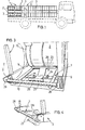
- La figure 1 est une vue schématique en élévation d'un camion chargé d'une batterie de dispositifs suivant l'invention.Figure 1 is a schematic elevational view of a truck loaded with a battery of devices according to the invention.
- La figure 2 est une vue schématique, à plus grande échelle que celle de la figure, suivant la ligne II-II de la figure 1.FIG. 2 is a schematic view, on a larger scale than that of the figure, along line II-II of FIG. 1.
- Les figures 3 et 4 sont des vues partielles, en perspective, montrant des détails du dispositif illustré aux figures 1 et 2.Figures 3 and 4 are partial perspective views showing details of the device illustrated in Figures 1 and 2.
- les figures 5 et 6 dont des vues analogues à la figure 2 et illustrent deux variantes du dispositif représenté aux figures 1 à 4.Figures 5 and 6 including views similar to Figure 2 and illustrate two variants of the device shown in Figures 1 to 4.
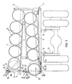
- La figure 7 est une vue en élévation d'une autre variante du dispositif suivant l'invention.Figure 7 is an elevational view of another variant of the device according to the invention.
- La figure 8 est une vue en coupe suivant la ligne VIII-VIII de la figure 7.Figure 8 is a sectional view along line VIII-VIII of Figure 7.
Dans les différentes figures, les mêmes notations de référence désignent des éléments identiques ou analogues.In the different figures, the same reference notations designate identical or analogous elements.
Le dispositif 1 suivant l'invention et représenté aux dessins est destiné à permettre le stockage, le transport et la manutention d'objets cylindriques 2, lourds et de mêmes dimensions , et en particulier des fûts, bonbonnes, etc... Ce dispositif comprend un bâti 3 présentant une ouverture d'entrée 4 agencée pour permettre l'introduction des fûts 2, un à un, dans le bâti 3 de manière à ce que leur axe soit sensiblement parallèle à la base 5 de l'ouverture 4 qui est de préférence sensiblement horizontal, un orifice de sortie 6 agencé pour permettre d'extraire, un à un les fûts 2 du bâti et situé à un niveau inférieur à celui de l'ouverture d'entrée 4, un chemin de roulement 7 s'étendant depuis l'ouverture d'entrée 4 jusqu'à l'orifice de sortie 6 et sur lequel les fûts se déplacent, l'un à la suite de l'autre, par gravité, des moyens 8 pour immobiliser, en amont de l'orifice de sortie 6, un fût 2 atteignant l'extrémité inférieure 9 du chemin de roulement 7 et des moyens 10, commandés par ce fût 2 immobilisé à l'extrémité inférieure du chemin de roulement pour immobiliser et maintenir à distance de ce fût les fûts situés en amont de ce dernier sur le chemin de roulement 7.The
Les dispositifs 1 sont destinés , par exemple et comme montré à la figure 1, à être disposés en batterie sur un véhicule routier. Ces dispositifs peuvent être, soit maintenus en place sur le plateau de chargement sous l'effet de leur propre poids et celui de leur contenu, soit fixés entre eux ou encore directement,comme montré à la figure 2, en 11, sur le châssis 12 du véhicule.The
Les dispositifs pourraient également être superposés sur deux ou plusieurs niveaux. C'est pourquoi, le bâti 3 du dispositif est avantageusement agencé pour permettre la superposition et la juxtaposition des dispositifs, ce bâti comprenant des moyens non représentés, tels que pattes d'assemblage coopérant avec des goujons, pour permettre la fixation du dispositif sur un support et des dispositifs entre eux, ces pattes d'assemblage pouvant être utilisées pour faciliter la manoeuvre des dispositifs à l'aide d'un engin de levage.The devices could also be superimposed on two or more levels. That is why, the
Pour éviter que le ou les fûts 2 situés à proximité de l'ouverture d'entrée 4 soient projetés à travers cette ouverture en cours de transport du dispositif, celui-ci comprend des moyens mobiles 13, disposés sur le bâti et en regard de l'ouverture 4, agencés pour autoriser l'introduction des fûts 2 dans le bâti et pour s'opposer à la sortie desdits fûts par l'ouverture 4, de sorte qu'un fût introduit dans le dispositif ne peut être extrait de celui-ci que par l'orifice de sortie 6. Pour que les fûts 2 puissent se déplacer correctement sur le chemin de roulement 7, sans coincement, le bâti est avantageusement pourvu de moyens de guidage 14 coopérant avec les bases 15 des fûts pour que les axes de ces derniers soient maintenus sensiblement perpendiculairement au chemin de roulement 7 pendant le trajet des fûts sur ce dernier.To prevent the barrel (s) 2 located near the inlet opening 4 from being thrown through this opening during transport of the device, the latter comprises
Les moyens 8 susdits comprennent, pour immobiliser un fût 2 en amont de l'orifice 6 et à l'extrémité 9 du chemin de roulement 7, un organe mobile 16 articulé, autour d'un axe 17 parallèle à l'axe des fûts 2, le long du bord supérieur de l'orifice de sortie 6. Cet organe est dirigé vers le chemin de roulement 7 de manière à s'étendre à travers ledit orifice 6, la distance séparant le chemin de roulement de l'extrémité libre 18 de cet organe 16, la plus proche dudit chemin de roulement, étant inférieure au diamètre d'un fût 2. Une butée 19 est prévue sur le bâti 3 pour coopérer avec ledit organe 16 afin de s'opposer au mouvement de rotation de ce dernier vers l'extérieur du bâti, suivant la flèche 20 (figure 2), pour bloquer le fût situé en regard de l'orifice 6 et autorise son mouvement vers l'intérieur du bâti, suivant la flèche 21, quand une pression est exercée sur l'organe, dans le sens de cette flèche 21, en vue du dégagement du fût situé à la partie inférieure du chemin de roulement . L'organe 16 est en outre agencé, par exemple par son propre poids ou sous l'action d'un ressort , pour s'appuyer automatiquement contre la butée 19 quand une pression dirigée suivant la flèche 21 n'est pas exercée sur ledit organe. Les moyens mobiles 13 susdits sont identiques aux moyens 8, le fût présenté à l'ouverture 4 exerçant une pression sur ces moyens suivant la flèche 21 de sorte que ceux-ci s'éclipsent vers l'intérieur du bâti pour autoriser l'introduction du fût dans le bâti. Immédiatement après le passage du fût, ces moyens 13 reprennent automatiquement leur position initiale contre la butée 19 et s'opposent à toute sortie, à travers l'ouverture 4, des fûts introduits dans le dispositif.The aforementioned means 8 comprise, for immobilizing a
Pour permettre le mouvement de l'organe 16 vers l'intérieur du bâti en vue du dégagement d'un fût, il faut pouvoir déplacer légèrement le fût 2 en_ regard de l'orifice 6 suivant la flèche 22 (figure 2). C'est pourquoi les moyens 10 sont prévus afin de maintenir un espace entre le fût susdit et les fûts situés en amont sur le chemin de roulement 7,de sorte que, lors du déplacement du fût considéré, ce déplacement n'entraîne pas automatiquement celui des fûts situés en amont,Les moyens 10, immobilisant et maintenant à distance du fût immobilisé à l'extrémité inférieure 9 du chemin de roulement les fûts situés en amont, sont constitués par un balancier 23, articulé sur le bâti autour d'un axe 24 parallèle aux axes des fûts disposés sur le chemin de roulement et situé à un niveau inférieur à celui de ce dernier, comprenant, de part et d'autre de cet axe, un élément 25, 26 s'étendant transversalement par rapport au chemin de roulement, ces éléments étant agencés pour que l'élément 26 le plus éloigné de l'orifice de sortie 6 soit automatiquement situé, en l'absence d'objet sur le chemin de roulement, en dessous du niveau de ce chemin de roulement 7 tandis que l'élément 25 du balancier le plus proche de l'orifice de sortie 6 fait saillie par rapport à ce chemin de roulement, ces éléments étant en outre agencés pour que l'élément 26 le plus éloigné de l'orifice de sortie bascule automatiquement pour se mettre en travers du chemin de roulement 7, lorsqu'un fût prend appui sur l'élément 25 le plus proche dudit orifice, pour immobiliser les fûts suivants, la distance séparant ces deux éléments 25 et 26 étant telle qu'un espace subsiste entre le fût le plus proche de l'orifice de sortie 6 est le fût qui le suit, cet espace étant calculé de manière à autoriser le mouvement de l'organe 16 suivant la flèche 21.To allow movement of the
Pour permettre un déchargement en série des fûts du dispositif, en particulier des fûts vides, l'axe 24 du balancier 23 peut être monté sur un support mobile agencé pour permettre d'écarter le balancier 23 du chemin de roulement 7 afin de rendre ce dernier inopérant. Il suffit alor= d'éclipser l'organe 16 vers l'intérieur du bâti et de rendre inopérant le balancier 23 pour que le dispositif se vide automatiquement des fûts qu'il contient.To allow the barrels of the device to be unloaded in series, in particular empty barrels, the
Pour faciliter la manutention du fût en voie d'extraction du dispositif, celui-ci peut comprendre, en aval de l'extrémité inférieure 9 du chemin de roulement et de l'orifice 6, un arrêt fixe 27 situé à un niveau supérieur à celui de cette extrémité 9. La distance séparant cet arrêt 27 de cette dernière est telle qu'un fût libéré du dispositif agit toujours sur le balancier 23 et s'immobilise sur le chemin de roulement 7 et contre l'arrêt 27, position dans laquelle il peut être très facilement pris en charge manuellement. Cet arrêt 27 est maintenu en place, comme montré à la figure 4, par des crochets 28, une rotation de ces crochets permettant d'éclipser l'arrêt 27 lors du déchargement en série des fûts.To facilitate handling of the barrel in the process of extracting the device, the latter may comprise, downstream from the
Comme illustré aux dessins, le dispositif peut être équipé pour contenir soit une rangée de fûts, soit plusieurs rangées. L'ouverture 4 et l'orifice 6 du dispositif peuvent, quand ce dernier peut contenir plusieurs rangées de fûts, être situées soit du même côté du dispositif, soit sur des côtés opposés de ce dernier.As illustrated in the drawings, the device can be equipped to contain either a row of drums or several rows. The opening 4 and the
La forme de réalisation représentée aux figures 7 et 8 est particulièrement avantageuse pour la livraison en détail des fûts. En effet, elle permet de placer dos à dos et en deux rangées les dispositifs sur un véhicule de sorte que les fûts peuvent toujours être déchargés à partir d'un trottoir. L'ouverture 4 et l'orifice 6 sont superposés et situés dans un même plan sensiblement vertical, le chemin de roulement 7 formant en coude 29. Quand les fûts sont pleins, ils peuvent ainsi être déchargés par l'orifice 6 à une hauteur idéale pour le manutentionnaire, tandis que les fûts vides peuvent être aisément introduits par ce dernier dans le dispositif, à travers l'ouverture 4. Pour éviter des chocs et des accélérations lors du passage des fûts dans le coude 29,1e dispositif comprend avantageusement des moyens 30 constitués, par exemple, par un amortisseur 31 absorbant les chocs dus à la chute des fûts 2 dans le coude et par une boucle 32, présentée par le chemin de roulement 7, coopérant avec l'amortisseur 31 pour freiner les fûts par frottement de ces derniers sur l'amortisseur et la boucle susdite.The embodiment shown in Figures 7 and 8 is particularly advantageous for the detailed delivery of drums. Indeed, it allows the devices to be placed back to back and in two rows on a vehicle so that the drums can always be unloaded from a sidewalk. The opening 4 and the
Il doit être entendu que l'invention n'est nullement limitée aux formes de réalisation décrites et que bien des modifications peuvent être apportées à ces dernières sans sortir du cadre du présent brevet.It should be understood that the invention is in no way limited to the embodiments described and that many modifications can be made to these without departing from the scope of this patent.
Claims (9)
Applications Claiming Priority (6)
| Application Number | Priority Date | Filing Date | Title |
|---|---|---|---|
| BE0/206737A BE891351A (en) | 1981-12-04 | 1981-12-04 | HORIZONTAL DISPENSER, BY GRAVITY, OF BEER AND CANDY BARRELS |
| BE206737 | 1981-12-04 | ||
| BE206915 | 1981-12-23 | ||
| BE0/206915A BE891599R (en) | 1981-12-04 | 1981-12-23 | HORIZONTAL DISPENSER, BY GRAVITY, OF BEER AND CANDY BARS |
| BE0/207595A BE892537R (en) | 1982-03-18 | 1982-03-18 | Horizontal gravity distributor of beer barrels - using pallet lift loads barrels onto vehicle chassis side by side over half width |
| BE207595 | 1982-03-18 |
Publications (1)
| Publication Number | Publication Date |
|---|---|
| EP0082129A1 true EP0082129A1 (en) | 1983-06-22 |
Family
ID=27158722
Family Applications (1)
| Application Number | Title | Priority Date | Filing Date |
|---|---|---|---|
| EP82870070A Withdrawn EP0082129A1 (en) | 1981-12-04 | 1982-12-03 | Device for storing, transporting and conveying cylindrical articles |
Country Status (1)
| Country | Link |
|---|---|
| EP (1) | EP0082129A1 (en) |
Cited By (7)
| Publication number | Priority date | Publication date | Assignee | Title |
|---|---|---|---|---|
| WO1994018099A1 (en) * | 1993-02-08 | 1994-08-18 | Mckesson Corporation | Container storing/dispensing assemblies for vehicle |
| WO1998033733A1 (en) * | 1997-02-03 | 1998-08-06 | Valmet-Karlstad Ab | Storage arrangement |
| FR2776994A1 (en) * | 1998-04-06 | 1999-10-08 | Textiles Ind Du Bassin D Annon | Storage installation for cylindrical objects e.g. rolls of cloth or paper |
| US6152670A (en) * | 1997-02-03 | 2000-11-28 | Valmet-Karlstad Ab | Storage arrangement for cores of a papermaking machine |
| CN103922061A (en) * | 2014-05-07 | 2014-07-16 | 宝钢发展有限公司 | Anti-rust paper goods shelf |
| CN108542196A (en) * | 2018-04-28 | 2018-09-18 | 云南鼎好仓储设备有限责任公司 | A kind of lifting shelf |
| CN109909966A (en) * | 2019-03-22 | 2019-06-21 | 浦项(张家港)不锈钢股份有限公司 | A kind of cylindrical shaped body storage rack |
Citations (7)
| Publication number | Priority date | Publication date | Assignee | Title |
|---|---|---|---|---|
| DD54297A (en) * | ||||
| US1985739A (en) * | 1933-08-18 | 1934-12-25 | Murray Paul | Vehicle body for barrels |
| US2115647A (en) * | 1937-04-19 | 1938-04-26 | William E Ross | Automatic barrel stacker and dispenser |
| US2755950A (en) * | 1953-12-04 | 1956-07-24 | Clifford G Forshey | Drum handling apparatus |
| GB784658A (en) * | 1955-09-27 | 1957-10-16 | R H Corbett & Company Ltd | Improvements in or relating to storage devices for cylindrical objects |
| US2818978A (en) * | 1954-03-01 | 1958-01-07 | Jack C Post | Barrel rack |
| DE2622582A1 (en) * | 1975-05-19 | 1976-12-09 | Cosan Crisplant As | STORAGE, TRANSPORT AND PROCESSING SYSTEM FOR OBJECTS |
-
1982
- 1982-12-03 EP EP82870070A patent/EP0082129A1/en not_active Withdrawn
Patent Citations (7)
| Publication number | Priority date | Publication date | Assignee | Title |
|---|---|---|---|---|
| DD54297A (en) * | ||||
| US1985739A (en) * | 1933-08-18 | 1934-12-25 | Murray Paul | Vehicle body for barrels |
| US2115647A (en) * | 1937-04-19 | 1938-04-26 | William E Ross | Automatic barrel stacker and dispenser |
| US2755950A (en) * | 1953-12-04 | 1956-07-24 | Clifford G Forshey | Drum handling apparatus |
| US2818978A (en) * | 1954-03-01 | 1958-01-07 | Jack C Post | Barrel rack |
| GB784658A (en) * | 1955-09-27 | 1957-10-16 | R H Corbett & Company Ltd | Improvements in or relating to storage devices for cylindrical objects |
| DE2622582A1 (en) * | 1975-05-19 | 1976-12-09 | Cosan Crisplant As | STORAGE, TRANSPORT AND PROCESSING SYSTEM FOR OBJECTS |
Cited By (7)
| Publication number | Priority date | Publication date | Assignee | Title |
|---|---|---|---|---|
| WO1994018099A1 (en) * | 1993-02-08 | 1994-08-18 | Mckesson Corporation | Container storing/dispensing assemblies for vehicle |
| WO1998033733A1 (en) * | 1997-02-03 | 1998-08-06 | Valmet-Karlstad Ab | Storage arrangement |
| US6152670A (en) * | 1997-02-03 | 2000-11-28 | Valmet-Karlstad Ab | Storage arrangement for cores of a papermaking machine |
| FR2776994A1 (en) * | 1998-04-06 | 1999-10-08 | Textiles Ind Du Bassin D Annon | Storage installation for cylindrical objects e.g. rolls of cloth or paper |
| CN103922061A (en) * | 2014-05-07 | 2014-07-16 | 宝钢发展有限公司 | Anti-rust paper goods shelf |
| CN108542196A (en) * | 2018-04-28 | 2018-09-18 | 云南鼎好仓储设备有限责任公司 | A kind of lifting shelf |
| CN109909966A (en) * | 2019-03-22 | 2019-06-21 | 浦项(张家港)不锈钢股份有限公司 | A kind of cylindrical shaped body storage rack |
Similar Documents
| Publication | Publication Date | Title |
|---|---|---|
| EP2536612A1 (en) | Chairlift seat having a bicycle transport device | |
| EP2451727B1 (en) | Static temporary storage device for motor vehicle body parts | |
| EP0082129A1 (en) | Device for storing, transporting and conveying cylindrical articles | |
| FR3013022A1 (en) | IMPROVED TRANSPORT TROLLEY | |
| FR2908103A1 (en) | TILT-TYPE TRAILER HAVING A LOADING AND UNLOADING DEVICE OF A LOAD | |
| FR2897027A1 (en) | Motorized or non-motorized pallet truck stowing device for lorry, has tie-bar with rod made of hard rubber and contacting claws of truck, and spring arranged around axial rod of tie-bar and supported on pin for drawing tie-bar downwards | |
| FR2773350A1 (en) | DEVICE FOR STORING AND TRANSPORTING A MOTORCYCLE | |
| FR3042750B1 (en) | DOUBLE-MEDIA RECLOSING BAR AND CORRESPONDING INSTALLATION METHOD. | |
| EP3219541A1 (en) | Set of two vehicles for distributing objects | |
| FR3057058A1 (en) | SETTING DEVICE FOR OBUS AND RECEPTACLE SUITABLE FOR RECEIVING SUCH A DEVICE | |
| FR2775238A1 (en) | DEVICE FOR AUTOMATICALLY SETTING CYLINDRICAL OR PARALLELEPIPEDIC PARTS AND WAGON USING SUCH A DEVICE | |
| EP2895411A1 (en) | Device for progressively unloading stacked loads | |
| FR2763909A1 (en) | MOTORCYCLE STORAGE AND TRANSPORT DEVICE | |
| FR2924415A1 (en) | CONTAINER OF AUTOMOTIVE SPARE PARTS | |
| EP1495994B1 (en) | Mobile refuse collecter | |
| WO2009080978A2 (en) | Device for conveying particles, installation and method for loading a container using the device | |
| EP1390684B1 (en) | Storage magazine for propellant charge modules | |
| FR2663010A1 (en) | STORAGE SYSTEM CONSISTING OF SEVERAL STORAGE ELEMENTS. | |
| FR2941219A1 (en) | VEHICLE EQUIPPED WITH HANDLING SYSTEM FOR REMOVABLE CONTAINERS | |
| WO2023118714A1 (en) | Improved system for supporting packaging for transporting radioactive materials, configured to allow it to pivot from a horizontal position for transport into a vertical position for use | |
| FR3021614A1 (en) | TRANSPORT TROLLEY OF STORAGE UNITS AND LOADING-UNLOADING STATION THEREOF | |
| FR2645129A1 (en) | Improvement to flow-storage installations | |
| BE389951A (en) | ||
| EP0677476A1 (en) | Device for transferring and handling elongated articles | |
| FR2877891A1 (en) | Boat launching device for boat carrying trailer, has cross-ties fixed on tubular structures of fair-leads and supporting rollers that are transversally moved for aligning cross-ties on origin rollers on trailer to slide hull towards rear |
Legal Events
| Date | Code | Title | Description |
|---|---|---|---|
| PUAI | Public reference made under article 153(3) epc to a published international application that has entered the european phase |
Free format text: ORIGINAL CODE: 0009012 |
|
| AK | Designated contracting states |
Designated state(s): BE DE FR GB LU NL |
|
| STAA | Information on the status of an ep patent application or granted ep patent |
Free format text: STATUS: THE APPLICATION IS DEEMED TO BE WITHDRAWN |
|
| 18D | Application deemed to be withdrawn |
Effective date: 19840601 |