EP0082036B1 - Moving map display - Google Patents
Moving map display Download PDFInfo
- Publication number
- EP0082036B1 EP0082036B1 EP82402133A EP82402133A EP0082036B1 EP 0082036 B1 EP0082036 B1 EP 0082036B1 EP 82402133 A EP82402133 A EP 82402133A EP 82402133 A EP82402133 A EP 82402133A EP 0082036 B1 EP0082036 B1 EP 0082036B1
- Authority
- EP
- European Patent Office
- Prior art keywords
- video
- map
- display
- signals
- video signal
- Prior art date
- Legal status (The legal status is an assumption and is not a legal conclusion. Google has not performed a legal analysis and makes no representation as to the accuracy of the status listed.)
- Expired
Links
Images


Classifications
-
- G—PHYSICS
- G01—MEASURING; TESTING
- G01C—MEASURING DISTANCES, LEVELS OR BEARINGS; SURVEYING; NAVIGATION; GYROSCOPIC INSTRUMENTS; PHOTOGRAMMETRY OR VIDEOGRAMMETRY
- G01C21/00—Navigation; Navigational instruments not provided for in groups G01C1/00 - G01C19/00
- G01C21/26—Navigation; Navigational instruments not provided for in groups G01C1/00 - G01C19/00 specially adapted for navigation in a road network
- G01C21/34—Route searching; Route guidance
- G01C21/36—Input/output arrangements for on-board computers
Definitions
- This invention relates to moving map displays.
- a moving map display As a navigational aid, or to show the topographical and other features of the terrain over which he is or will be flying. This is particularly true for the pilot of an aircraft where the terrain may be obscured by cloud cover or darkness.
- Some advanced radar systems are capable of generating an image of the terrain immediately surrounding the aircraft.
- the terrain radar display contains only limited information and the radar image must be correlated with a navigational map in order to provide the pilot with useful information, such as labels identifying pertinent topographic features and landmarks.
- Moving map displays have been developed that utilize film strips that have been laboriously fabricated from many individual maps of smaller areas, which when combined from the total film strip.
- US-A-3,697,681 describes a system for positioning a high resolution image having a narrow field of view on a composite wide angle display.
- the system comprises a plurality of scanned raster devices such as television monitors which are arranged so that a collective image is shown on the monitors in such a way that the image appears to be continuous from one monitor to another.
- EP-A-0 022 703 describes a moving map display for showing features and other information regarding the area around a moving aircraft, corresponding to the preamble of present claim 1, and having a navigation system thereon to indicate the position of the aircraft.
- a mapped area is made up of a number of contiguous smaller area map segments each of which is stored as a video signal in a video stoarge means.
- An intermediate storage means is used between the video storage means and the display.
- a moving map display showing features and other information regarding the area about a moving craft wherein a navigation system indicates the position of the craft on said display, wherein a mapped area is made up of a number of contiguous smaller area map segments with each map segment being stored as a video signal in a video disk player, and wherein said map display displays a composite map that may be made up of portions of more than one stored map segments, the display further comprising:
- the video signals for the selected map segments are read out of video signal storage in parallel.
- a microprocessor controls video switching apparatus to select portions of the signal read out to be combined to make up a new composite map frame video signal used to display an area with the vehicle being located at the middle thereof.
- the new composite map frame signal is continuously changed or updated and the vehicle moves to keep the vehicle at the middle of the display.
- video signal storage means such as commercial video disk is so large that a standard twelve inch disk can storage fifty six thousand map segments. This permit a single video disk to store different map scales and overlay information for each map segment as desired by the equipment operator.
- Other video signal storage means such as magnetic drums, or other analog signal storage means may also be utilized.
- FIG. 1 is shown the schematic block diagram for my invention.
- a video disk is used as the video signal storage means storing raster scan format video signals for the map segments.
- Navigation system 10 may be any one of the many navigation systems known in the art that provide output information regarding the present position of a vehicle or other craft on which navigation system 10 is located.
- the position information is also used as an input to microprocessor 11.
- Microprocessor 11 utilizes this information to look up in memory 12 the track that is to be accessed by video disk player 13 that has the video signal recorded thereon necessary to display a primary map segment for the area in which the vehicle containing navigation system 10 and my novel moving map display is located.
- micro- processor 11 utilizes information in memory 12 to locate other tracks on the video disk containing video signals for map segments adjacent to the primary map segment. The finer details regarding storage of video signals for map segments and the manner in which they are read out are described further in this specification.
- Video disk player 13 may be made up of one, two, or four commercial video disk players operating in tandem or, preferrably, may be one video disk player with two playback heads.
- the reason for two playback heads in the preferred embodiment of video disk player 13 is to concurrently read out video signals stored on two different tracks of the video disk.
- These video signals are both applied to first video switch 14 which is under the control of microprocessor 11 which also controls the second video switch 15.
- Micro- processor 11 controls video switches 14 and 15 to selectively switch the video signal to delay circuits 16 and 17 and to summing circuits 18,19 and 20 to make up a new video signal which has vertical and horizontal sync pulses added thereto.
- the sync pulses and other timing signals are provided by timing pulse and waveform generator 21 which operates synchronously with the video disk player using methods that are well known in the art.
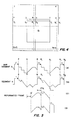
- FIG 2 therein is shown a large map 30 broken up into a plurality of rows and columns of map segments. No typical map information is shown thereon to avoid cluttering up Figure 2 and thereby detracting from an understanding of the present invention.
- FIG 2 there are n columns by m rows of map segments making up a total of mn map segments. The designations on some of these map segments are self-explanatory.
- FIG 3 is shown a blow-up of nine of the map segments shown in Figure 2.
- navigation system 10 provides information to micro-processor 11 indicating the position of the vehicle upon which navigation system 10 and my novel moving map display are located.
- the vehicle position is represented by the (9 on map segment n + 4 in Figure 3.
- the moving map display system does not just display map segment n + 4. Rather, a new map portion represented by the bounds T, Q, G, and H is displayed. This requires that portions of map segments 3, 4, n + 3, and n + 4 be selected and combined to make up the new composite map segment represented by the bounds T, Q, G, and H. This is accomplished by the teaching or my invention.
- map segments chosen to make up a new composite map segment depend upon the position of the vehicle in the area shown by primary map segment n + 4.
- the vehicle is located within quadrant A of the map segment n + 4 and, therefore, portions of map segments 3, 4, n + 3, and n + 4 are required to make up the new map segment.
- portions of map segment 4, 5, n + 4, and n + 5 would be required to make up the new map segment.
- microprocessor 11 in the moving map display system must first determine the primary map segment n + 4 covering the area in which the vehicle is located and then must determine which of the four quadrants thereof in which the vehicle is located. This is accomplished using look up tables stored in memory 12. The identity of the primary map segment and the appropriate quadrant thereof are used to address memory 12 and the information read out of the memory identifies the position of the four tracks on the disk.
- the video signals for map segments 3, 4, n + 3, and n + 4 must be read out and the appropriate portions thereof selected and combined to make up the video signal for the composite map segment designated by the bounds T, Q, G, and H.
- the two playback heads of video disk player 13 are initially positioned to concurrently read out the video signals for map segments 3 and 4 are completely read out. The two playback heads are then switched to the video disk tracks containing the video signals for map segments n + 3 and n + 4 and the video signals for these two map segments are read out during the next revolution of the video disk.
- the playback heads are then repositioned to again read the video disk tracks containing the video signals for map segments 3 and 4.
- This switching and reading process is repeated for the video disk tracks containing the video signals for map segments 3, 4, n + 3, and n + 4 until the vehicle upon which the moving map display equipment is located moves to another quadrant of map segment n + 4 or another quadrant in one of map segments 3, 4, or n + 3.
- micro- processor 11 determines which new four map segments are to be read out and in what order to continue generating a video signal for the composite map segment showing the position of the vehicle at the center thereof.
- the speed at which the read out head or other device means can switch from track to track will decrease.
- map segments 3, 4, n + 3 and n + 4 are recorded on four adjacent tracks of a video disk and when microprocessor 11 determines that the vehicle is in one of the aforementioned map segments and quadrants, the same group of four video disk tracks are read out.
- Microprocessor 11 is programmed with simple mathematical relationships, and knowing the present position of the vehicle from the navigation equipment as represented by 0 it can mathematically determine the corners T, Q, G, and H as shown in Figure 3, but not in Figure 4. As part of the above, it is also a simple mathematical calculation for microprocessor 11 to determine on which scan lines and how far across particular scan lines the video signals being read off a track of the video disk must be selected or rejected to make up the new video signal for the composite map segment.
- the two record heads are concurrently reading the two tracks on the video disk which contain the video signals for map segments 3 and 4.
- the video signals being read off tracks 3 and 4 represent a raster scanning beam starting at the upper left hand corners of the squares representing map segments 3 and 4 and sweep from left to right across the block and repeat this left to right sweep starting at the top of the block and progressing down to the bottom of the blocks in the conventional television raster format.
- a new composite video signal is to be made up for the new map segment having the ⁇ 8 at its center and requiring portions of the video signals of map segments 3, 4, n + 3, and n + 4 to make up same.
- the microprocessor 11 determines from the navigation system input that the vehicle upon which the moving map display equipment is located lies in quadrant A of map segment n + 4, it uses this information to address memory 12 from which it reads the video disk track addresses for the video signals for map segments 3, 4, n + 3, and n + 4.
- Signals are then sent to video disk player 13 causing the read heads or other read mechanisms to initially position the two read heads on the tracks containing the video signals for map segments 3 and 4.
- the video signals required to completely display map segments 3 and 4 have been read off the disk in parallel and are forwarded to first video switch 14 so that portions thereof may be selected under the control of microprocessor 11.
- the read heads are then position to read the tracks containing the video signals for map segments n + 3 and n + 4 during the next revolution of the video disk. More particularly, as the video signals for map segments 3 and 4 are read off the disk in parallel they are initially blocked at first video switch 14 (see Figure 1) as the signal figuratively sweeps from left to right and from top to bottom before the scan lines simultaneously sweeps starting at points P and S for these two map segments.
- switch 14 As switch 14 is disabled from passing through the portion of scan lines between points P and Q for map segment 3 it is enabled to pass through the video signal for map segment 4 between points S and T. Likewise, when disabled from passing video signal for map segment 3 between points Q and R it is disabled from passing signal between points T and U.
- the signal that appears first at the output of switch 14 is that portion of the scan line of map segment 4 between points S and T and immediately thereafter that portion of the signal for the scan line of map segment 3 between points Q and R.
- the time order in which these signals appear is backwards and must be corrected for.
- These two signal segments are placed in the proper time sequence in the following manner.
- the video information for two adjacent raster scan lines, ST and S 1 T, for example, is essentially identical.
- Video switch 14 is thus enabled to pass the video information to a first scan line between the points or time period represented by Q and R.
- Video switch 14 is then enabled to pass the video information for the segment 5 1 T, during the second or next scan line.
- the video information for the period QR is placed before the video information for the period ST for a scan line of the new map segment. If the video information on 5, T, is significantly different enough to cause difficulty this can be accommodated by recording frames 4 and n + 4 so that they are offset by one at the time the video disk is made.
- FIG 5 at lines (A) and (B) are seen representative video signals for two horizontal scan lines read off two video disk tracks respectively designated map segment 3 and map segment 4.
- the same letter designations are used on Figure 5 as used in Figure 4 to represent portions of the video signal and the horizontal retrace signal. That is, the horizontal retrace signals with blanking pulse and other color burst information occur in the periods RS and UV.
- the time periods PQ, QR, ST, and TU are also shown.
- the video signal for the two scan lines of one track are shown identical but in reality this may not be so.
- video switch 14 is first disabled so as not to pass the video information occuring in the time period PQ, but is at the same time enabled to pass the video signal occuring in the time period ST for map segment 4 in line (B). Thereafter, video switch 14 is enabled to pass the video signal in line (A) of Figure 5 during the period QR but at the same time is disabled from passing the video signal during the period TU for map segment 4 in line (B). Video switch 14 switches the video signal for the period QR of map segment 3 through delay circuit 16, the delay of which is equal to the horizontal retrace time, RS, and thence through video switch 15 to summing circuit 18.
- Video switch 14 is controlled by microprocessor 11 to pass the video signal for the period ST of map segment 4 directly to the second input of summing circuit 18.
- the output from summing circuit 18 is the video wave form shown in line (C) of Figure 5 and has the desired effect of removing the horizontal retrace period RS that would occur in the middle of the mixed video signal portions.
- the reformated video signal shown in line (C) which is the output from summing 18 is passed through delay circuit 17, the delay of which is equal to the vertical retrace time, to summing circuit 19, and then to summing circuit 20 to be mixed with new horizontal retrace information to make up the video output signal for the new map segment.
- Timing pulse and wave form generator 21 is the clock circuit for micro- processor 11 which in conjunction with timing track signals from video disk 13 helps micro- processor 11 determine when to operate video switches 14 and 15.
- microprocessor 11 causes pulses to be output from circuit 21 to the other two inputs of summing circuit 20 to add in horizontal retrace pulse and color burst information seen in Figure 5 (D).
- the operation of the circuits in handling vertical retrace information is described hereinafter. As the read heads of video disk player 13 are reading the last raster scan line of both map segments 3 and 4 before vertical retrace signals, microprocessor 11 is aware of this due to the timing information it is receiving from circuit 21.
- Microprocessor 11 enables video switch 14 to pass the video signal for map segment 4 during the time period ST for the last scan line of map segment 4 but at this time disables video switch 14 from passing video signal for the subsequent period QR. Following the last reaster scan line of both map segments 3 and 4 the two read heads are reading out vertical blanking, vertical sync pulses and other control signals during the vertical retrace time as known in the art. Following the vertical retrace period microprocessor 11 is enabling and disabling switch 14 to pass through those portions of the video signals for map segments n + 3 and n + 4 in the manner just described for map segments 3 and 4 to finish making up the video signal for the new map segment. However, the vertical retrace period just mentioned will cause a band to appear across the map display.
- This band is deleted in a manner similar to that in which the horizontal retrace information was deleted.
- the reformated video signal for that portion of the new map segment made up of video signals from map segments 3 and 4 has been passing through delay line 17 to summing circuit 19 up to this time.
- microprocessor 11 operates video switch 15 to route the signals in a different fashion. That portion of the video signal coming from map segment n + 3 is switched through delay circuit 16 to video switch 15 which then routes the signal directly to summing circuit 19 rather than to circuits 17 and 18 as done up to this point in time.
- Video switch 14 switches the portion of the video signal from map segment n + 4 completely past circuits 15, 16, 17 and 18 to summing circuit 19.
- the signal output from summing circuit 19 is a video signal deleting the vertical and horizontal retrace pulses and other sync signals as originally read off the video disk.
- Summing circuit 20 then is used to add in sync signals such as horizontal and vertical sync and color burst information to the video signal to make up the complete composite video signal for the new map frame segment.
- the video signal for two of the four tracks is delayed on the disk by a time period equal to the horizontal retrace time.
- the data stored for map segments 3 and n + 3 is delayed by a period equal to the horizontal retrace period.
- map overlay information for each map segment may be stored on the video disk and portions thereof may be read off and combined with the video signal for the composite map segment.
- the composite map segment displayed would have the overlay information thereon.
- map segments making up maps of different scales may be stored and in response to a scale indication from the operator of the moving map display the map segments of the indicated scale are selectively read out to make up the composite map segment displayed on the moving map display.
- the video signal for the time period QR may be input to an analog shift register such as a charge coupled device (CCD) shift register and the micro- processor taps this shift register at an appropriate point to remove the signal therefrom so that it appears immediately following time period ST.
- CCD charge coupled device
- the digital signal would then be reconverted to analog and be mixed with the other analog signal to make .up the video signal for the new map segment.
Description
- This invention relates to moving map displays.
- It is often desirable to provide for the operator of a moving vehicle, particularly an aircraft, a moving map display as a navigational aid, or to show the topographical and other features of the terrain over which he is or will be flying. This is particularly true for the pilot of an aircraft where the terrain may be obscured by cloud cover or darkness. Some advanced radar systems are capable of generating an image of the terrain immediately surrounding the aircraft. However, the terrain radar display contains only limited information and the radar image must be correlated with a navigational map in order to provide the pilot with useful information, such as labels identifying pertinent topographic features and landmarks. Moving map displays have been developed that utilize film strips that have been laboriously fabricated from many individual maps of smaller areas, which when combined from the total film strip.
- US-A-3,697,681 describes a system for positioning a high resolution image having a narrow field of view on a composite wide angle display. The system comprises a plurality of scanned raster devices such as television monitors which are arranged so that a collective image is shown on the monitors in such a way that the image appears to be continuous from one monitor to another.
- EP-A-0 022 703 describes a moving map display for showing features and other information regarding the area around a moving aircraft, corresponding to the preamble of
present claim 1, and having a navigation system thereon to indicate the position of the aircraft. A mapped area is made up of a number of contiguous smaller area map segments each of which is stored as a video signal in a video stoarge means. An intermediate storage means is used between the video storage means and the display. - It is an object of the present invention to provide a moving map display where the need for an intermediate storage means is obviated.
- According to the invention there is provided a moving map display showing features and other information regarding the area about a moving craft wherein a navigation system indicates the position of the craft on said display, wherein a mapped area is made up of a number of contiguous smaller area map segments with each map segment being stored as a video signal in a video disk player, and wherein said map display displays a composite map that may be made up of portions of more than one stored map segments, the display further comprising:
- video switching means under control of a processor, connected to said navigation system indicating the position of said craft for selecting, in response to information from the navigation system, ones of said stored map segments, portions of the video signals of which are required to make up said composite map to be displayed, characterized in that the video disk player comprises a video disk having two tracks thereon, the video switching means comprising:
- a first video switch under control of said processor for selecting portions of the video signals read by two independent heads from the two tracks on the video disk player; and
- combining means including a second video switch also under control of said processor for combining said selected portions of the video signals to make up a new video signal used to display said composite map segment.
- The video signals for the selected map segments are read out of video signal storage in parallel. A microprocessor controls video switching apparatus to select portions of the signal read out to be combined to make up a new composite map frame video signal used to display an area with the vehicle being located at the middle thereof. The new composite map frame signal is continuously changed or updated and the vehicle moves to keep the vehicle at the middle of the display.
- The capacity of video signal storage means such as commercial video disk is so large that a standard twelve inch disk can storage fifty six thousand map segments. This permit a single video disk to store different map scales and overlay information for each map segment as desired by the equipment operator. Other video signal storage means such as magnetic drums, or other analog signal storage means may also be utilized.
- The invention will now be described with reference to the accompanying drawings where:
- - Figure 1 is a system schematic block diagram of the present invention;
- - Figure 2 represents a large map broken up into a number of map segments;
- - Figure 3 is a blow-up of nine adjacent map segments from which a new map segment is to be made;
- - Figure 4 is a more detailed representation of four adjacent map segments, video signals for which are stored on video signal storage means and portions thereof are combined to form the video signal for a new composite map segment;
- - Figure 5 shows a representation of video signals stored on video signal storage means and how portions of them are combined to make up a composite video signal for a new map segment.
- In Figure 1 is shown the schematic block diagram for my invention. In the following description a video disk is used as the video signal storage means storing raster scan format video signals for the map segments.
Navigation system 10 may be any one of the many navigation systems known in the art that provide output information regarding the present position of a vehicle or other craft on whichnavigation system 10 is located. In addition to the output information fromnavigation system 10 being displayed in some conventional well-known manner (not shown), the position information is also used as an input to microprocessor 11. Microprocessor 11 utilizes this information to look up inmemory 12 the track that is to be accessed byvideo disk player 13 that has the video signal recorded thereon necessary to display a primary map segment for the area in which the vehicle containingnavigation system 10 and my novel moving map display is located. In addition, micro- processor 11 utilizes information inmemory 12 to locate other tracks on the video disk containing video signals for map segments adjacent to the primary map segment. The finer details regarding storage of video signals for map segments and the manner in which they are read out are described further in this specification. -
Video disk player 13 may be made up of one, two, or four commercial video disk players operating in tandem or, preferrably, may be one video disk player with two playback heads. The reason for two playback heads in the preferred embodiment ofvideo disk player 13 is to concurrently read out video signals stored on two different tracks of the video disk. These video signals are both applied tofirst video switch 14 which is under the control of microprocessor 11 which also controls thesecond video switch 15. Micro- processor 11 controlsvideo switches circuits circuits waveform generator 21 which operates synchronously with the video disk player using methods that are well known in the art. - Turning now to Figure 2, therein is shown a
large map 30 broken up into a plurality of rows and columns of map segments. No typical map information is shown thereon to avoid cluttering up Figure 2 and thereby detracting from an understanding of the present invention. As may be seen in Figure 2, there are n columns by m rows of map segments making up a total of mn map segments. The designations on some of these map segments are self-explanatory. - In Figure 3 is shown a blow-up of nine of the map segments shown in Figure 2. In operation,
navigation system 10 provides information to micro-processor 11 indicating the position of the vehicle upon whichnavigation system 10 and my novel moving map display are located. By way of example, the vehicle position is represented by the (9 on map segment n + 4 in Figure 3. In order to show the position of the vehicle the moving map display system does not just display map segment n + 4. Rather, a new map portion represented by the bounds T, Q, G, and H is displayed. This requires that portions ofmap segments - In viewing Figure 3, it is obvious that the map segments chosen to make up a new composite map segment depend upon the position of the vehicle in the area shown by primary map segment n + 4. In the example just given the vehicle is located within quadrant A of the map segment n + 4 and, therefore, portions of
map segments map segment memory 12. The identity of the primary map segment and the appropriate quadrant thereof are used to addressmemory 12 and the information read out of the memory identifies the position of the four tracks on the disk. - With the example shown in Figure 3, with the position of the vehicle being located in quadrant A of map segment n + 4, the video signals for
map segments video disk player 13 are initially positioned to concurrently read out the video signals formap segments map segments map segments map segments - Utilizing the data compression techniques disclosed immediately hereinafter the number of times a given map segment must be recorded on a video disk is minimized. Other data compression techniques may also be utilized. For example, when the vehicle is located within quadrant A of map segment n + 4,
map segments map segment 4, the same four map segments are read out in the exact same order. When the vehicle is located in quadrant D ofmap segment 3, or in quadrant B of map segment n + 3, again the same four map segments are read out in the same order. Thus,map segments - Turning now to Figure 4 to describe how portions of the video signals of
map segments map segments tracks map segments - With the particular example represented in Figure 4, a new composite video signal is to be made up for the new map segment having the <8 at its center and requiring portions of the video signals of
map segments memory 12 from which it reads the video disk track addresses for the video signals formap segments video disk player 13 causing the read heads or other read mechanisms to initially position the two read heads on the tracks containing the video signals formap segments map segments first video switch 14 so that portions thereof may be selected under the control of microprocessor 11. The read heads are then position to read the tracks containing the video signals for map segments n + 3 and n + 4 during the next revolution of the video disk. More particularly, as the video signals formap segments map segments map segment 3 from point P to point Q the signal read off the video disk is blocked atswitch 14 but during the period between the points Q and R for each remaining sweep the signal read off the disk is passed throughvideo switch 14. For the period of time between points R and S for each remaining sweep the signal formap segment 3 is blocked as it contains horizontal retrace signals which are not required. During this same period of time for the complete scan lines between points P and S the second head is reading the video signal formap segment 4 between points S and V. Asswitch 14 is disabled from passing through the portion of scan lines between points P and Q formap segment 3 it is enabled to pass through the video signal formap segment 4 between points S and T. Likewise, when disabled from passing video signal formap segment 3 between points Q and R it is disabled from passing signal between points T and U. - From a time flow of events, however, the signal that appears first at the output of
switch 14 is that portion of the scan line ofmap segment 4 between points S and T and immediately thereafter that portion of the signal for the scan line ofmap segment 3 between points Q and R. The time order in which these signals appear is backwards and must be corrected for. These two signal segments are placed in the proper time sequence in the following manner. The video information for two adjacent raster scan lines, ST and S1 T, for example, is essentially identical.Video switch 14 is thus enabled to pass the video information to a first scan line between the points or time period represented by Q andR. Video switch 14 is then enabled to pass the video information for the segment 51 T, during the second or next scan line. In this manner, the video information for the period QR is placed before the video information for the period ST for a scan line of the new map segment. If the video information on 5, T, is significantly different enough to cause difficulty this can be accommodated byrecording frames 4 and n + 4 so that they are offset by one at the time the video disk is made. - One other problem now arises by operating in this manner. Although the video information for the period QR now occurs prior to the video information for the period ST within a single scan line of the new map segment the time period RS has not been taken into account. In a time flow of events the video signal for the period QR occurs first, then the period RS from which the horizontal blanking information has been blocked occurs, followed by the video information for the period ST. The period RS in the middle of the new frame or segment must be deleted in the manner described with reference to Figures 1 and 5.
- In Figure 5 at lines (A) and (B) are seen representative video signals for two horizontal scan lines read off two video disk tracks respectively designated
map segment 3 andmap segment 4. The same letter designations are used on Figure 5 as used in Figure 4 to represent portions of the video signal and the horizontal retrace signal. That is, the horizontal retrace signals with blanking pulse and other color burst information occur in the periods RS and UV. The time periods PQ, QR, ST, and TU are also shown. The video signal for the two scan lines of one track are shown identical but in reality this may not be so. As previously described, and with reference to line (A) of Figure 5,video switch 14 is first disabled so as not to pass the video information occuring in the time period PQ, but is at the same time enabled to pass the video signal occuring in the time period ST formap segment 4 in line (B). Thereafter,video switch 14 is enabled to pass the video signal in line (A) of Figure 5 during the period QR but at the same time is disabled from passing the video signal during the period TU formap segment 4 in line (B).Video switch 14 switches the video signal for the period QR ofmap segment 3 throughdelay circuit 16, the delay of which is equal to the horizontal retrace time, RS, and thence throughvideo switch 15 to summingcircuit 18.Video switch 14 is controlled by microprocessor 11 to pass the video signal for the period ST ofmap segment 4 directly to the second input of summingcircuit 18. The output from summingcircuit 18 is the video wave form shown in line (C) of Figure 5 and has the desired effect of removing the horizontal retrace period RS that would occur in the middle of the mixed video signal portions. The reformated video signal shown in line (C) which is the output from summing 18 is passed throughdelay circuit 17, the delay of which is equal to the vertical retrace time, to summingcircuit 19, and then to summingcircuit 20 to be mixed with new horizontal retrace information to make up the video output signal for the new map segment. Timing pulse andwave form generator 21 is the clock circuit for micro- processor 11 which in conjunction with timing track signals fromvideo disk 13 helps micro- processor 11 determine when to operatevideo switches circuit 21 to the other two inputs of summingcircuit 20 to add in horizontal retrace pulse and color burst information seen in Figure 5 (D). The operation of the circuits in handling vertical retrace information is described hereinafter. As the read heads ofvideo disk player 13 are reading the last raster scan line of both mapsegments circuit 21. Microprocessor 11 enablesvideo switch 14 to pass the video signal formap segment 4 during the time period ST for the last scan line ofmap segment 4 but at this time disablesvideo switch 14 from passing video signal for the subsequent period QR. Following the last reaster scan line of both mapsegments switch 14 to pass through those portions of the video signals for map segments n + 3 and n + 4 in the manner just described formap segments map segments delay line 17 to summingcircuit 19 up to this time. At this point in time, microprocessor 11 operatesvideo switch 15 to route the signals in a different fashion. That portion of the video signal coming from map segment n + 3 is switched throughdelay circuit 16 tovideo switch 15 which then routes the signal directly to summingcircuit 19 rather than tocircuits Video switch 14 switches the portion of the video signal from map segment n + 4 completelypast circuits circuit 19. Thus, the signal output from summingcircuit 19 is a video signal deleting the vertical and horizontal retrace pulses and other sync signals as originally read off the video disk. Summingcircuit 20 then is used to add in sync signals such as horizontal and vertical sync and color burst information to the video signal to make up the complete composite video signal for the new map frame segment. - In an alternative embodiment of the invention, in each of the groups offourtracks/map segments previously described, the video signal for two of the four tracks is delayed on the disk by a time period equal to the horizontal retrace time. Referring to Figure 4, the data stored for
map segments 3 and n + 3 is delayed by a period equal to the horizontal retrace period. The result is that the signal read by the first read headreading map segment 3 doesn't start reading the portion of video signal originally starting at the rime represented bypoint Q, but rather starts reading that portion of video signal by an amount of time that is equal to the horizontal retrace time later or an interval represented between points R and S. The result is that the portion of video signal from the first read head that previously terminated at the point R now terminates at the point S, just as the signal frommap segment 4 commences. This eliminates the need for horizontal retracedelay line 16, in order to make the signal portions contiguously sequential. - Another variation of this idea is not to shift the signal on the disk but to physically move or offset the first read head to accomplish the same delay. Similarly, at the appropriate moment in time both heads may be mechanically or electronically offset to effectively add or remove the
vertical delay line 17 in Figure 1. - Using the techniques described above map overlay information for each map segment may be stored on the video disk and portions thereof may be read off and combined with the video signal for the composite map segment. The composite map segment displayed would have the overlay information thereon.
- With the large capacity of the video disk, map segments making up maps of different scales may be stored and in response to a scale indication from the operator of the moving map display the map segments of the indicated scale are selectively read out to make up the composite map segment displayed on the moving map display.
- It would be obvious to one skilled in the art that other approaches may be used to reverse the time order of appearance of the video signal portions in the time period QR and ST. For example, the video signal for the time period QR may be input to an analog shift register such as a charge coupled device (CCD) shift register and the micro- processor taps this shift register at an appropriate point to remove the signal therefrom so that it appears immediately following time period ST. The digital signal would then be reconverted to analog and be mixed with the other analog signal to make .up the video signal for the new map segment.
- While what has been described above is the preferred embodiment of the invention it would be obvious to those skilled in the art that many changes and modifications may be made thereto without departing from the scope of the invention as defined in the claims. For example, as the video disk player art advances the read mechanisms therein may be able to switch between tracks fast enough to eliminate the present requirement for two or more playheads and thereby eliminate the need to organize map segments on adjacent tracks as previously described.
and
Claims (5)
Applications Claiming Priority (2)
| Application Number | Priority Date | Filing Date | Title |
|---|---|---|---|
| US06/325,610 US4400727A (en) | 1981-11-27 | 1981-11-27 | Moving map display |
| US325610 | 1989-03-20 |
Publications (2)
| Publication Number | Publication Date |
|---|---|
| EP0082036A1 EP0082036A1 (en) | 1983-06-22 |
| EP0082036B1 true EP0082036B1 (en) | 1987-07-08 |
Family
ID=23268613
Family Applications (1)
| Application Number | Title | Priority Date | Filing Date |
|---|---|---|---|
| EP82402133A Expired EP0082036B1 (en) | 1981-11-27 | 1982-11-23 | Moving map display |
Country Status (3)
| Country | Link |
|---|---|
| US (1) | US4400727A (en) |
| EP (1) | EP0082036B1 (en) |
| DE (1) | DE3276719D1 (en) |
Families Citing this family (36)
| Publication number | Priority date | Publication date | Assignee | Title |
|---|---|---|---|---|
| JPS57169785A (en) * | 1981-04-13 | 1982-10-19 | Nissan Motor | Travelling guidance system for car |
| JPS57186111A (en) * | 1981-05-13 | 1982-11-16 | Nissan Motor Co Ltd | Map display device for vehicle |
| US4660037A (en) * | 1982-01-28 | 1987-04-21 | Honda Giken Kogyo Kabushiki Kaisha | Current location indication apparatus for use in an automotive vehicle |
| US5019828A (en) * | 1982-02-24 | 1991-05-28 | Schoolman Scientific Corp. | High resolution navigation and mapping system |
| MX152578A (en) * | 1982-03-10 | 1985-09-09 | Natividad Gene Esparza | IMPROVEMENTS TO THE COMPUTERIZED ELECTRONIC SYSTEM TO OBTAIN URBAN COORDINATES |
| US4485409A (en) * | 1982-03-29 | 1984-11-27 | Measuronics Corporation | Data acquisition system for large format video display |
| US4630065A (en) * | 1982-05-17 | 1986-12-16 | Honda Giken Kogyo Kabushiki Kaisha | Current location indication apparatus for use in an automotive vehicle |
| US4550317A (en) * | 1982-09-29 | 1985-10-29 | Toyota Jidosha Kabushiki Kaisha | Drive guide display system for motor vehicle |
| JPS59174714A (en) * | 1983-03-25 | 1984-10-03 | Nippon Denso Co Ltd | Vehicle mounted electronic map display device |
| JPS59174713A (en) * | 1983-03-25 | 1984-10-03 | Nippon Denso Co Ltd | Vehicle mounted map display device |
| JPS59183458A (en) * | 1983-04-01 | 1984-10-18 | Hitachi Ltd | Picture retrieving system |
| US4549275A (en) * | 1983-07-01 | 1985-10-22 | Cadtrak Corporation | Graphics data handling system for CAD workstation |
| US4499491A (en) * | 1983-07-21 | 1985-02-12 | Allied Corporation | Moving map display using optical tunnel |
| BR8407020A (en) * | 1983-08-16 | 1985-07-30 | Waldemar S Thorwaldson | AIRCRAFT POSITION INDICATION SYSTEM FOR AIRCRAFT PASSENGERS |
| FR2560037B1 (en) * | 1984-02-28 | 1988-04-08 | Thomson Cgr | METHOD FOR CONTROLLING THE POSITIONING OF A PATIENT IN RELATION TO A RADIOLOGY FACILITY, AND ARRANGEMENT FOR CARRYING OUT SAID METHOD |
| JPS61117986A (en) * | 1984-11-13 | 1986-06-05 | Nippon Kogaku Kk <Nikon> | Reproducing device of electronic camera system |
| US4660096A (en) * | 1984-12-11 | 1987-04-21 | Rca Corporation | Dividing high-resolution-camera video signal response into sub-image blocks individually raster scanned |
| JPS61250671A (en) * | 1985-04-27 | 1986-11-07 | 株式会社デンソー | Map display unit |
| US4815012A (en) * | 1986-02-05 | 1989-03-21 | Allied-Signal Inc. | Apparatus and method for real time reconstruction of digital map data |
| US5138460A (en) * | 1987-08-20 | 1992-08-11 | Canon Kabushiki Kaisha | Apparatus for forming composite images |
| US7594250B2 (en) * | 1992-04-02 | 2009-09-22 | Debey Henry C | Method and system of program transmission optimization using a redundant transmission sequence |
| US5701582A (en) * | 1989-08-23 | 1997-12-23 | Delta Beta Pty. Ltd. | Method and apparatus for efficient transmissions of programs |
| FR2665316B1 (en) * | 1990-07-27 | 1992-10-09 | Thomson Trt Defense | METHOD FOR PROCESSING IMAGES FOR THE DETECTION OF HORIZON AND DEVICE FOR IMPLEMENTING SAME. |
| US5187571A (en) * | 1991-02-01 | 1993-02-16 | Bell Communications Research, Inc. | Television system for displaying multiple views of a remote location |
| JP3108122B2 (en) * | 1991-04-25 | 2000-11-13 | パイオニア株式会社 | Car navigation system |
| US5321798A (en) * | 1991-10-28 | 1994-06-14 | Hughes Aircraft Company | Apparatus for providing a composite digital representation of a scene within a field-of-regard |
| US5532737A (en) * | 1993-05-03 | 1996-07-02 | Bell Communications Research, Inc. | Camera arrangement with wide field of view |
| US5682525A (en) | 1995-01-11 | 1997-10-28 | Civix Corporation | System and methods for remotely accessing a selected group of items of interest from a database |
| US6199015B1 (en) | 1996-10-10 | 2001-03-06 | Ames Maps, L.L.C. | Map-based navigation system with overlays |
| US5884219A (en) * | 1996-10-10 | 1999-03-16 | Ames Maps L.L.C. | Moving map navigation system |
| US7092012B2 (en) * | 1996-11-15 | 2006-08-15 | Canon Kabushiki Kaisha | Image processing apparatus and method, storage medium, and communication system |
| US8172702B2 (en) | 2000-06-16 | 2012-05-08 | Skyhawke Technologies, Llc. | Personal golfing assistant and method and system for graphically displaying golf related information and for collection, processing and distribution of golf related data |
| US7118498B2 (en) | 2000-06-16 | 2006-10-10 | Skyhawke Technologies, Llc | Personal golfing assistant and method and system for graphically displaying golf related information and for collection, processing and distribution of golf related data |
| US7121962B2 (en) | 2000-12-19 | 2006-10-17 | Reeves G George | Golf round data system with cellular telephone and player help features |
| FR2920243B1 (en) * | 2007-08-21 | 2009-10-30 | Airbus France Sas | METHODS AND DEVICES FOR REAL-TIME GENERATION OF MAPPING FUNDS |
| CN107434146B (en) * | 2016-05-25 | 2020-04-28 | 北京北方华创微电子装备有限公司 | Method and device for conveying materials on equipment and material conveying equipment |
Citations (1)
| Publication number | Priority date | Publication date | Assignee | Title |
|---|---|---|---|---|
| US3697681A (en) * | 1970-08-25 | 1972-10-10 | Singer Co | Placement of image on matrix display |
Family Cites Families (3)
| Publication number | Priority date | Publication date | Assignee | Title |
|---|---|---|---|---|
| US3507993A (en) * | 1968-01-04 | 1970-04-21 | Us Navy | Situation display for aircraft navigation employing crt display of the mean course line |
| US4103435A (en) * | 1976-10-08 | 1978-08-01 | The United States Of America As Represented By The Secretary Of The Navy | Head trackable wide angle visual system |
| FR2461305B1 (en) * | 1979-07-06 | 1985-12-06 | Thomson Csf | MAP INDICATOR SYSTEM MORE PARTICULARLY FOR AIR NAVIGATION |
-
1981
- 1981-11-27 US US06/325,610 patent/US4400727A/en not_active Expired - Fee Related
-
1982
- 1982-11-23 DE DE8282402133T patent/DE3276719D1/en not_active Expired
- 1982-11-23 EP EP82402133A patent/EP0082036B1/en not_active Expired
Patent Citations (1)
| Publication number | Priority date | Publication date | Assignee | Title |
|---|---|---|---|---|
| US3697681A (en) * | 1970-08-25 | 1972-10-10 | Singer Co | Placement of image on matrix display |
Also Published As
| Publication number | Publication date |
|---|---|
| DE3276719D1 (en) | 1987-08-13 |
| EP0082036A1 (en) | 1983-06-22 |
| US4400727A (en) | 1983-08-23 |
Similar Documents
| Publication | Publication Date | Title |
|---|---|---|
| EP0082036B1 (en) | Moving map display | |
| US4360876A (en) | Cartographic indicator system | |
| EP0341645B1 (en) | Digital mapping display apparatus | |
| US4752836A (en) | Method and apparatus for reproducing video images to simulate movement within a multi-dimensional space | |
| US4873585A (en) | Method of selectively retrieving video images from a video reproducer for simulating movement | |
| EP0077107B1 (en) | A picture display arrangement | |
| US4463380A (en) | Image processing system | |
| US4635136A (en) | Method and apparatus for storing a massive inventory of labeled images | |
| US4513374A (en) | Memory system | |
| US4644401A (en) | Apparatus for combining graphics and video images in multiple display formats | |
| US4107665A (en) | Apparatus for continuous variation of object size on a raster type video screen | |
| GB2136653A (en) | Video editing viewer | |
| GB1507220A (en) | Video colour display system | |
| JPS6362753B2 (en) | ||
| EP0235594B1 (en) | Apparatus and method for real time reconstruction of digital map data | |
| US4845631A (en) | Scrolling image memory for high speed avionics moving map display | |
| EP0336764A2 (en) | Pixel and line enhancement method and apparatus | |
| JPH023592B2 (en) | ||
| EP0014045B1 (en) | Apparatus for controlling a display | |
| US4755956A (en) | Freeze frame apparatus for moving map display system | |
| EP0191822B1 (en) | Interactive video and audio controller | |
| US4754966A (en) | Circuit for forming objects in a video picture | |
| US4774572A (en) | Video scan conversion | |
| US5161031A (en) | Apparatus for processing data for a video tape recorder | |
| JPS6412778A (en) | Reproducing method |
Legal Events
| Date | Code | Title | Description |
|---|---|---|---|
| PUAI | Public reference made under article 153(3) epc to a published international application that has entered the european phase |
Free format text: ORIGINAL CODE: 0009012 |
|
| 17P | Request for examination filed |
Effective date: 19821203 |
|
| AK | Designated contracting states |
Designated state(s): DE FR GB IT SE |
|
| RAP1 | Party data changed (applicant data changed or rights of an application transferred) |
Owner name: ALLIED CORPORATION |
|
| ITF | It: translation for a ep patent filed |
Owner name: ING. ZINI MARANESI & C. S.R.L. |
|
| GRAA | (expected) grant |
Free format text: ORIGINAL CODE: 0009210 |
|
| AK | Designated contracting states |
Kind code of ref document: B1 Designated state(s): DE FR GB IT SE |
|
| REF | Corresponds to: |
Ref document number: 3276719 Country of ref document: DE Date of ref document: 19870813 |
|
| ET | Fr: translation filed | ||
| PLBE | No opposition filed within time limit |
Free format text: ORIGINAL CODE: 0009261 |
|
| STAA | Information on the status of an ep patent application or granted ep patent |
Free format text: STATUS: NO OPPOSITION FILED WITHIN TIME LIMIT |
|
| 26N | No opposition filed | ||
| PG25 | Lapsed in a contracting state [announced via postgrant information from national office to epo] |
Ref country code: GB Effective date: 19881123 |
|
| PG25 | Lapsed in a contracting state [announced via postgrant information from national office to epo] |
Ref country code: SE Effective date: 19881124 |
|
| GBPC | Gb: european patent ceased through non-payment of renewal fee | ||
| PG25 | Lapsed in a contracting state [announced via postgrant information from national office to epo] |
Ref country code: FR Free format text: LAPSE BECAUSE OF NON-PAYMENT OF DUE FEES Effective date: 19890731 |
|
| PG25 | Lapsed in a contracting state [announced via postgrant information from national office to epo] |
Ref country code: DE Effective date: 19890801 |
|
| REG | Reference to a national code |
Ref country code: FR Ref legal event code: ST |
|
| EUG | Se: european patent has lapsed |
Ref document number: 82402133.1 Effective date: 19890726 |