EP0081449B1 - Comminuting apparatus - Google Patents
Comminuting apparatus Download PDFInfo
- Publication number
- EP0081449B1 EP0081449B1 EP19820630099 EP82630099A EP0081449B1 EP 0081449 B1 EP0081449 B1 EP 0081449B1 EP 19820630099 EP19820630099 EP 19820630099 EP 82630099 A EP82630099 A EP 82630099A EP 0081449 B1 EP0081449 B1 EP 0081449B1
- Authority
- EP
- European Patent Office
- Prior art keywords
- rotor
- stator
- pellets
- fluid
- receiving region
- Prior art date
- Legal status (The legal status is an assumption and is not a legal conclusion. Google has not performed a legal analysis and makes no representation as to the accuracy of the status listed.)
- Expired
Links
- 239000008188 pellet Substances 0.000 claims description 81
- 239000012530 fluid Substances 0.000 claims description 52
- 230000002093 peripheral effect Effects 0.000 claims description 37
- 239000002002 slurry Substances 0.000 claims description 34
- 239000002245 particle Substances 0.000 claims description 24
- 239000004636 vulcanized rubber Substances 0.000 claims description 12
- 239000000463 material Substances 0.000 claims description 11
- 239000011148 porous material Substances 0.000 claims description 11
- 238000000034 method Methods 0.000 claims description 10
- 238000011144 upstream manufacturing Methods 0.000 claims description 9
- 239000000203 mixture Substances 0.000 claims description 5
- 238000004891 communication Methods 0.000 claims description 4
- XLYOFNOQVPJJNP-UHFFFAOYSA-N water Substances O XLYOFNOQVPJJNP-UHFFFAOYSA-N 0.000 claims description 3
- 238000005086 pumping Methods 0.000 claims 5
- 230000003467 diminishing effect Effects 0.000 claims 2
- 229920001971 elastomer Polymers 0.000 description 7
- 238000005299 abrasion Methods 0.000 description 3
- 230000007423 decrease Effects 0.000 description 3
- 239000000806 elastomer Substances 0.000 description 3
- 239000004575 stone Substances 0.000 description 3
- 230000004075 alteration Effects 0.000 description 2
- 238000006073 displacement reaction Methods 0.000 description 2
- 239000011521 glass Substances 0.000 description 2
- 230000003993 interaction Effects 0.000 description 2
- 238000004519 manufacturing process Methods 0.000 description 2
- 238000012986 modification Methods 0.000 description 2
- 230000004048 modification Effects 0.000 description 2
- 229920005989 resin Polymers 0.000 description 2
- 239000011347 resin Substances 0.000 description 2
- 230000000007 visual effect Effects 0.000 description 2
- 239000003082 abrasive agent Substances 0.000 description 1
- 239000000919 ceramic Substances 0.000 description 1
- 239000003245 coal Substances 0.000 description 1
- 230000006835 compression Effects 0.000 description 1
- 238000007906 compression Methods 0.000 description 1
- 238000010586 diagram Methods 0.000 description 1
- 230000013011 mating Effects 0.000 description 1
- TWNQGVIAIRXVLR-UHFFFAOYSA-N oxo(oxoalumanyloxy)alumane Chemical compound O=[Al]O[Al]=O TWNQGVIAIRXVLR-UHFFFAOYSA-N 0.000 description 1
- 230000002250 progressing effect Effects 0.000 description 1
- 230000000750 progressive effect Effects 0.000 description 1
- 238000012958 reprocessing Methods 0.000 description 1
- 238000005096 rolling process Methods 0.000 description 1
- 238000010008 shearing Methods 0.000 description 1
- HBMJWWWQQXIZIP-UHFFFAOYSA-N silicon carbide Chemical compound [Si+]#[C-] HBMJWWWQQXIZIP-UHFFFAOYSA-N 0.000 description 1
- 229910010271 silicon carbide Inorganic materials 0.000 description 1
- 239000007787 solid Substances 0.000 description 1
- 229920001169 thermoplastic Polymers 0.000 description 1
- 229920001187 thermosetting polymer Polymers 0.000 description 1
- 239000004416 thermosoftening plastic Substances 0.000 description 1
- -1 woods Substances 0.000 description 1
Images



Classifications
-
- B—PERFORMING OPERATIONS; TRANSPORTING
- B02—CRUSHING, PULVERISING, OR DISINTEGRATING; PREPARATORY TREATMENT OF GRAIN FOR MILLING
- B02C—CRUSHING, PULVERISING, OR DISINTEGRATING IN GENERAL; MILLING GRAIN
- B02C7/00—Crushing or disintegrating by disc mills
- B02C7/02—Crushing or disintegrating by disc mills with coaxial discs
- B02C7/08—Crushing or disintegrating by disc mills with coaxial discs with vertical axis
-
- B—PERFORMING OPERATIONS; TRANSPORTING
- B02—CRUSHING, PULVERISING, OR DISINTEGRATING; PREPARATORY TREATMENT OF GRAIN FOR MILLING
- B02C—CRUSHING, PULVERISING, OR DISINTEGRATING IN GENERAL; MILLING GRAIN
- B02C2/00—Crushing or disintegrating by gyratory or cone crushers
- B02C2/10—Crushing or disintegrating by gyratory or cone crushers concentrically moved; Bell crushers
Definitions
- This application pertains to the art of particle comminuting and more particularly to one pass comminuting of centimeter sized pellets or particles to micron sized particulates.
- the invention is particularly applicable to comminuting vulcanized rubber and will be described with particular reference thereto. However, it is to be appreciated that the invention has other applications such as comminuting coal, thermoplastics, thermosetting plastics, woods, ceramics, glass, resins, and other materials.
- comminution apparatae commonly include a rotor and a stator which have opposing surfaces.
- the opposing surfaces define a central material receiving region and have surrounding abrasive surfaces that defined a grinding zone therebetween.
- An urging means urges the rotor and stator together as the rotor is rotated about an axis.
- the materials are commonly reduced to micron sized particles.
- various methods and apparatus have been employed to reduce the elastomeric materials to micron size.
- the prior art apparatus have had certain drawbacks, particularly when used for commercial production.
- One method for producing small particulates has been to subject material to a cryogenic temperature.
- the embrittled material is ground by conventional grinding techniques. Commonly, the ground particles are large and must be refrozen and ground another time before they can be reused efficiently. Thus, this technique is expensive and finds great difficulty in producing particles in the lower micron range.
- Others have used abrasion devices for reducing the particle size of rubber and other elastomers. However, abrasion devices have relatively low particle yields. Further, abrasion devices have an inherent temperature increase that causes a hazard of the rubber combusting. Moreover, the elevated temperatures involved in prior art methods tend to degrade the material being processed.
- the present invention provides an apparatus which although relatively simple in design and operation efficiently produces micron sized particles.
- a comminuting apparatus having a rotor and a stator which have opposing surfaces that define a receiving region therebetween and peripheral abrasive surfaces that define a grinding zone therebetween, an urging means for urging at least one of the stator and the rotor toward the other, and means for rotating the rotor about an axis, said apparatus having at least two recesses on said stator with an orientation in an outward flow direction from said axis, at least the same number of similarly oriented recesses, on said rotor and an outward sloping portion at an outward end of said rotor recesses oriented in a direction generally opposed to the direction of rotation about said axis;
- pressurizing means for increasing the pressure along said rotor recesses disposed within the receiving region.
- the invention may take form in various parts and arrangements of parts.
- the FIGURES are only for purposes of illustrating a preferred embodiment of the invention and are not to be construed as limiting the invention.
- a feeding means A feeds fluid and pellets of the vulcanized rubber or other elastomer to be comminuted at coordinated rates.
- the pellets are chunks which have a maximum cross sectional dimension on the order of a centimeter or less.
- the apparatus may be scaled up to handle larger pellets.
- a mixing means 8 receives the pellets and fluid and mixes them into a slurry.
- the slurry is fed to a mill C which grinds the pellets into micron sized particles preferably with 90% of the particles by number having a diameter on the order of 20 microns or less.
- the feeding means A includes a pellet feeding means for feeding pellets at a selectable rate and a fluid feeding means for feeding fluid commensurate with the rate that the slurry is fed to the mill.
- the pellet feeding means includes a hopper 10 which discharges the pellets into a vibratory feeder 12.
- the vibratory feeder includes a generally horizontal trough 14 which is mounted on springs 16 and vibrated by a motor 18.
- the vibratory feeder 12 moves the pellets at a rate controlled by the speed or duty cycle of the motor 18.
- a plurality of vibratory feeders may be used.
- the fluid feeding means includes a water or other fluid inlet 20 and a level controlled valve 22.
- the mixing means B includes a mixing tank 30 which receives pellets from the pellet feeding means and fluid from the fluid feeding means.
- An agitating means 32 mixes the pellets and fluid into a slurry.
- the slurry is pumped by a positive displacement pump 34 driven by a variable speed pump motor 36 from the mixing tank 30 through a feed line 38 to the mill C.
- the pump 34 is a progressing cavity positive displacement pump or other pump which supplies the slurry to the mill with a generally constant pressure.
- the fluid level in the mixing tank is maintained substantially constant by the fluid feeding means which adds fluid at the same rate that pump 34 pumps fluid from the tank.
- the slurry feed line 38 is of sufficiently small diameter that the slurry velocity maintains the pellets suspended in the slurry but not so small that the pump 34 or pump motor 36 are overloaded.
- the mill C has a mill housing 40 upon which are mounted a plurality, four in the preferred embodiment, of upward extending posts, including posts 42 and 44.
- a stator mounting bracket 46 in which a stator 48 is mounted is slidably disposed on the posts for longitudinal, but not rotational, movement relative thereto.
- Connected between each of the posts and the stator mounting bracket 46 is a plurality of fluid cylinders, including cylinders 50 and 52 for urging the stator mounting bracket and stator relative to the mill housing with a preselected force or load.
- a rotor motor 60 such as 75 kilowatt (100 horsepower) motor, is mounted in a mill frame which is rigidly secured to the mill housing 40.
- the rotor motor 60 is coupled to a shaft 62 which is supported on the mill housing 40 by a thrust bearing 64.
- Mounted on the end of the mill shaft 62 is a rotor plate 66 for supporting a rotor 68.
- a central portion of the rotor 68 and the stator 48 define a receiving region 70 for receiving the pellet and fluid slurry from the mixing means B.
- a peripheral region of the stator 48 and rotor 68 define a grinding zone 72 for comminuting the pellets into micron sized particles.
- An impeller 74 is disposed in the said receiving region 70 to facilitate movement of the pellets into the grinding zone 72.
- the particles and the fluid passing from the grinding zone 72 are collected in a trough 76 and pass through an outlet pipe 78. Downstream, not shown, the comminuted rubber particles and the fluid are separated.
- stator 48 is a unitary abrasive structure.
- the stator 48 has a central, slurry receiving aperture 80 surrounded by a receiving region 70 (FIG. 1A) defined by a generally conical shaped upper stator abrasive surface 82 and by a generally peripheral stator abrasive surface 84 which itself surrounds the receiving region 70.
- the stator 48 has a plurality, four in the preferred embodiment, of stator recesses, such as recess 86, which provide fluid communication between the slurry receiving region 70 (FIG. 1A) and the grinding zone 72 (FIG. 1A).
- stator recesses note stator recess 86, extends generally radially from a first or receiving region end 88 to a second or grinding zone end 90.
- the rotor 68 is a unitary abrasive structure.
- the rotor has a central receiving region surface 100, for the lower portion of the central receiving region 70 (FIG. 1A), which supports the impeller 74, consisting of a base plate 120 and vertical vanes 121, and a peripheral generally conical shaped abrasive surface 102 extending therearound.
- the stator and rotor peripheral abrasive surfaces 84 and 102 interact to define the grinding zone 72 (FIG. 1A) therebetween.
- the rotor 68 has a plurality of recesses, eight in the preferred embodiment such as recess 104, which provide a path for the pellets between the slurry receiving region 70 (FIG. 1A) and the grinding zone 72 (FIG. 1A).
- Each rotor recess note rotor recess 104, has a receiving region end 106 and a grinding zone end 108. Further, each rotor recess has an upstream portion 110 in the direction of the rotation which is larger than the pellets and a trailing portion 112 which is smaller than the upstream portion. The trailing portion 112 wedges the pellets against the stator peripheral abrasive surface 84 and into the grinding zone 72 (FIG. 1A).
- the impeller 74 is mounted on the rotor 68 for rotation therewith.
- the impeller 74 includes a base plate 120which is mounted on the rotor receiving region surface 100 and a plurality of removably attached generally vertical vanes 121.
- Generally vertical is to connote that the vanes extend within the slurry receiving region 70 (FIG. 1A) and between the rotor receiving region surface 100 and stator receiving region abrasive surface 82 and impel the fluid and pellets toward the rotor recesses such as recess 104.
- Each vane 121 has a top or outward edge 122 which engages the stator receiving region abrasive surface 82.
- the stator receiving region abrasive surface 82 wears the outward impeller edge 122 at a corresponding rate. This maintains a fluid seal between the impeller vanes 121 and the stator receiving region surface 82 to improve the impelling action.
- the impeller tends to draw the slurry from the mixing means B (FIG. 1), changes the slurry flow from axial to radial, and impels the slurry with substantially even pressure into the grinding zone 72 (FIG. 1A).
- the impelling action of the impeller 74 pumps the pellets and fluid into the rotor recesses 104, etc.
- the centrifugal force from the rotation of the rotor recesses further urges the pellets and fluid through the rotor recesses.
- the highest pressure is developed at the outer or second end 108 of the rotor recesses.
- a view is taken of cutaway portions of upper stator 48 and lower rotor 68, shown for convenience as a horizontal view, as the rotor 68 rotates past the stator 48 from left to right.
- the view is taken in a direction from the stator grinding zone end 90 toward the stator abrasive surface 82 in the region of the stator peripheral abrasive surface 84.
- a pellet 130 is received in the rotor recess 104 and carried along the stator.
- the pellet tends to move toward the stator recess 86.
- some pellets may return to the receiving region 70 (FIG. 1A) through the stator recess, other pellets are caught between the recesses as they move out of alignment (FIGURES 6D and 6E).
- the pellets are stretched and wedged into the grinding zone 72 (FIGURES 6F, 6G and 61). The pellet is stretched between the rotor and stator recesses 104 and 86 and peripheral abrasive surfaces 102 and 84 as the recesses 104 and 86 move apart.
- At least one and preferably both of the stator and rotor peripheral abrasive surfaces 84 and 102 have a plurality of pores, such as pore 132, which have a median pore size of about 10-200 microns. Between pores, the abrasive surfaces have substantially smooth regions 134. Although shown separated for ease of illustration, the smooth regions 134 of the stator and rotor slide generally along each other creating a shearing interaction. This cuts the vulcanized rubber of the pellets into smaller particles, generally on the order of the size of pores 132.
- the composition of the stator and rotor grinding surfaces 84 and 102 is such that the median pore size is 10-200 microns.
- a pore size of 50 microns has been found to be effective for comminuting vulcanized rubber to particles having by weight a median diameter of 50 microns and by number 90% of the particles having a diameter of less than 20 microns.
- the rotor and stator are constructed of silicon carbide with a grit size in the range of 36to 60 mesh or aluminum oxide with a grit size in the range of 46 to 80 mesh. Other pore sizes may be used to obtain larger or smaller comminuted particles or when comminuting pellets of other materials.
- these abrasives are vitreous bonded with about 22% glass by weight, although resin bonding and other bonding techniques may be used.
- These compositions have an interconnected porosity.
- the rotor and stator are a P hardness or higher, the preferred embodiment being a T hardness, as commonly defined by the grinding wheel industry.
- the grits will not have the smooth surfaces 134 asthe stones are manufactured. To achieve these flat surfaces, the stones are lapped together to wear sharper naturally occurring edges flat.
- the stator and rotor recesses may be cut or molded into the stone composition.
- an electric control circuit is provided to maintain the concentration of pellets in the grinding zone within a range which produces satisfactory results.
- control circuit adjusts the feed rate of pellets into the mixing tank to maintain the power drawn by the rotor motor 60 substantially constant.
- the control increases the pellet feed rate relative to the fluid feed rate when the motor draws less than a preselected amount of power and reduces the pellet feed rate relative to the fluid feed rate when more than the selected amount of the power is drawn.
- the electrical control circuit includes first and second electric power lines 150 and 152.
- a watt transducer 154 is connected with the rotor motor 60 to monitor the amount of power (kilowatts) drawn thereby.
- a digital kilowatt meter 156 is connected with the watt transducer to provide a visual display of the instantaneous amount of power being drawn by the rotor motor.
- a calibration circuit 158 connects the watt transducer with a maximum kilowatt selector means 160.
- the maximum kilowatt selection means 160 has dials, or the like, on which an operator selects a maximum power which the rotor motor is to be allowed to draw.
- the maximum power selector means 160 When the amount of power monitored by the watt transducer 154 is below the amount of power selected by the operator, the maximum power selector means 160 is in its activated state. When the amount of power monitored by the watt transducer meets or exceeds the selected maximum power, the maximum power selector means takes on its deactivated state. In its activated state, the maximum watt selector means 162 closes a normally open relay contact 162 and opens a normally closed relay contact 164. The normally open maximum power selector contact 162 controls the coil of a pilot relay 170. The maximum power pilot relay 170 has a normally open contact 172, shown in the lower portion of FIG. 7 which is used in controlling the vibratory feeding means 12.
- the maximum power selector means 160 takes on its deactivated state opening the normally open contacts 162 and 172 and closing the normally closed contact 164.
- the maximum watt selector normally closed relay contact 164 controls an indicator lamp 166 for indicating that pellets are not being fed to the mixing tank.
- a pump motor overload control means is provided.
- a speed controller 180 controls the speed at which the pump motor 36 is operated.
- a speed selection potentiometer 182 allows the operator to select the speed at which the pump motor is to be operated and a speed indicator 184 provides a visual indication of the present pump motor speed.
- the speed controller produces a signal which varies in proportion to the amount of current being drawn by the pump motor 36 on a pair of terminals 186.
- a maximum current selector means 190 has dials, or the like, on which the operator selects a maximum current at which the pump motor is to be operated. The maximum current selector means 190 compares the selected maximum current with the current indicated on terminals 186.
- the maximum current selector means maintains the pump motor current below the maximum by controlling the pellet feeding means 12 to keep the slurry sufficiently fluid.
- the maximum current selector means closes a normally closed contact 192 and opens a normally open contact 194.
- the normally closed contact 192 controls an indicator lamp 196 which indicates that the pump motor is running with less than the maximum current.
- the normally open maximum current selector contact 194 controls a maximum current pilot relay 200.
- the maximum current pilot relay 200 controls a normally open contact 202 for controlling the rate at which pellets are fed into the mixing tank.
- the normally open maximum power pilot relay contact 172 and the normally open maximum current pilot relay contact 202 are connected in series with the vibratory feeding means 12.
- a variable solid state device 204 controls the amount of power delivered to the vibratory feeder means motor 18 to control its frequency and amplitude of vibration.
- FIGURES 8-13 illustrate another stator and rotor configuration in accordance with the present invention.
- like elements with the embodiment of FIGURES 1-5 are denoted with the same reference numerals followed by a prime (').
- FIGURE 8 there is shown a mill housing 40' which is stationarily mounted. Extending upward from the mill housing are a plurality of upward extending posts, including posts 42' and 44'. The posts extend slidably through apertures in a stator support bracket 46' which holds a stator 48'. This enables the stator support bracket to move longitudinally on the posts but prohibits it from rotating.
- each of the posts Connected to each of the posts is a plurality of fluid cylinders, including cylinders 50' and 52' for urging the stator support bracket toward the mill housing with a selected constant force.
- a load of 900-4500 kilograms (2000 to 10,000 pounds) has been found to produce satisfactory results for 25 centimeter (10 inch) diameter stators and rotors.
- Increases in the slurry pressure from the pump increase the preferred load.
- the fluid, preferably hydraulic, cylinders continue to exert the same force as the stator moves longitudinally to compensate for wear on the stator and rotor abrasive surfaces. Because the stator and rotor are urged together by the fluid cylinders with a constant load but not held at a fixed spacing, the rotor and stator may undergo limited longitudinal movement with respect to each other as the pellets pass into the grinding zone.
- a mill shaft 52' rotates a plate 66' and a rotor 68' in mating cooperation with the stator.
- the rotor and stator define a slurry receiving region 70' and a grinding zone 72' therebetween.
- An impeller 74' is mounted on the rotor for rotation therewith.
- the stator includes a plurality of stator recesses extending outward from the receiving region 70' into a peripheral abrasive surface 84'. Because each of the stator recesses is the same, a stator recess 86' is described in detail and it is to be appreciated that the description applies by analogy to the other stator recesses.
- the stator recess 86' has an upstream edge 210 which is first engaged as the rotor 68' rotates.
- the stator 48' has a trailing edge 212 opposite to the upstream edge 210.
- An enlarged portion or relief area 214 which tapers generally between the full depth of the recess 86' to the level of the stator peripheral abrasive surface 84' extends downstream from the stator recess tailing edge 212.
- the stator recess 86' has an inside or receiving region end 216 in communication with the slurry receiving recess 86' and an outer or grinding zone end 218 in the grinding zone 72'.
- the rotor 68' has a central receiving region surface 100' disposed adjacent the slurry receiving region 70' and a peripheral abrasive surface 102'. Extending outward from the slurry receiving region 70' into the grinding zone 72' are a plurality of generally P-shaped rotor recesses 104', in the preferred embodiment 8 P-shaped rotor recesses. Because each of the plurality of rotor recesses is substantially identical, a typical rotor recess 104' is described in detail and it is to be appreciated that the description applies by analogy to the other rotor recesses.
- the rotor recesses 104' have an upstream edge 110' in the direction of rotation and a trailing edge 112' opposite the upstream edge 110'.
- the trailing edge 112' includes a downstream enlarged portion or relief area 220 in which a recess base wall tapers or cams generally from the lowest depth of the recess 104' toward the rotor peripheral abrasive surface 102'.
- the rotor recess relief area 220 has an arched perimeter, in the preferred embodiment.
- Each rotor recess 104' further has a first or receiving region end 106' disposed in fluid communication with the recess 104', for receiving slurry, and a second or outer end 108' separated by a small land 222 on the peripheral abrasive surface 102' from the edge of the rotor 68'.
- the pellets are impelled outward into the rotor recesses 104' by the impeller 74'. Centrifugal force from the rotation of the rotor 68' accelerates the pellets with greater pressure toward the outer end 108' of the rotor recesses 104'. As the rotor recesses 104' come into alignment with the stator recesses 86', the stator recesses 86' provide a return path for some of the fluid and pellets to the receiving region 70'.
- pellets become wedged or cammed between the stator recess relief area 214 and either the rotor recess relief area 220 or the rotor peripheral abrasive surface and other pellets become wedged between the rotor recess relief area 220 and the stator recess relief area 214 or the stator peripheral abrasive surface 102'. With continued rotation, the pellets are stretched and wedged into the grinding zone 72' and are comminuted as described above.
Landscapes
- Engineering & Computer Science (AREA)
- Food Science & Technology (AREA)
- Mechanical Engineering (AREA)
- Processing And Handling Of Plastics And Other Materials For Molding In General (AREA)
Description
- This application pertains to the art of particle comminuting and more particularly to one pass comminuting of centimeter sized pellets or particles to micron sized particulates. The invention is particularly applicable to comminuting vulcanized rubber and will be described with particular reference thereto. However, it is to be appreciated that the invention has other applications such as comminuting coal, thermoplastics, thermosetting plastics, woods, ceramics, glass, resins, and other materials.
- As shown, for example, in W. German Patent Application DE-A-2 936194, which forms the preamble of claim 1, comminution apparatae commonly include a rotor and a stator which have opposing surfaces. The opposing surfaces define a central material receiving region and have surrounding abrasive surfaces that defined a grinding zone therebetween. An urging means urges the rotor and stator together as the rotor is rotated about an axis.
- To facilitate reprocessing of vulcanized rubber and other elastomeric materials for reuse, the materials are commonly reduced to micron sized particles. Heretofore, various methods and apparatus have been employed to reduce the elastomeric materials to micron size. However, the prior art apparatus have had certain drawbacks, particularly when used for commercial production. One method for producing small particulates has been to subject material to a cryogenic temperature. The embrittled material is ground by conventional grinding techniques. Commonly, the ground particles are large and must be refrozen and ground another time before they can be reused efficiently. Thus, this technique is expensive and finds great difficulty in producing particles in the lower micron range. Others have used abrasion devices for reducing the particle size of rubber and other elastomers. However, abrasion devices have relatively low particle yields. Further, abrasion devices have an inherent temperature increase that causes a hazard of the rubber combusting. Moreover, the elevated temperatures involved in prior art methods tend to degrade the material being processed.
- Accordingly, it has been found desirable to provide an effective method and apparatus for comminuting of a vulcanized rubber and other elastomers to micron sized particles to facilitate reuse. The present invention provides an apparatus which although relatively simple in design and operation efficiently produces micron sized particles.
- In accordance with the invention there is provided a comminuting apparatus having a rotor and a stator which have opposing surfaces that define a receiving region therebetween and peripheral abrasive surfaces that define a grinding zone therebetween, an urging means for urging at least one of the stator and the rotor toward the other, and means for rotating the rotor about an axis, said apparatus having at least two recesses on said stator with an orientation in an outward flow direction from said axis, at least the same number of similarly oriented recesses, on said rotor and an outward sloping portion at an outward end of said rotor recesses oriented in a direction generally opposed to the direction of rotation about said axis;
- supplying meansfor supplying a mixture of fluid and vulcanized rubber-like pellets to be reduced in size to said receiving region; and,
- pressurizing means for increasing the pressure along said rotor recesses disposed within the receiving region.
- Furthermore according to the invention, a method of comminuting particles is disclosed, in which said method includes the steps of
- receiving the slurry of vulcanized rubber or rubber-like pellets with a median diameter of at least 3 mm and water in said receiving region disposed between said rotor and stator;
- urging the pellets along said outward extending recesses in said rotor abrasive surface surrounding the receiving region by rotating said rotor, said rotor recess having a sloping portion along said trailing edge relative to the direction of rotation;
- wedging the pellets between said rotor recess sloping portion and said stator peripheral abrasive surface surrounding the receiving region and into the grinding zone defined between the rotor and stator zone defined between the rotor and stator peripheral abrasive surfaces;
- continuing rotation of said rotor comminuting the pellets in a single pass into particles between said stator and rotor peripheral abrasive surfaces until the particles have a median diameter of less than 50 microns.
- The invention may take form in various parts and arrangements of parts. The FIGURES are only for purposes of illustrating a preferred embodiment of the invention and are not to be construed as limiting the invention.
- FIGURE 1 is a side elevational view in partial section of a comminuting apparatus in accordance with the present invention;
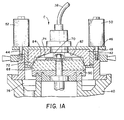
- FIGURE 1A is an enlarged copy of the stator/ rotor region of FIGURE 1 with additional reference numerals.
- FIGURE 2 is a bottom view of the face of the stator of FIGURE 1;
- FIGURE 3 is a sectional view through section 3-3 of the stator of FIGURE 2;
- FIGURE 4 is a side elevational view of the rotor of FIGURE 1;
- FIGURE 5 is a top view of the rotor of FIGURE 1 with the impeller in phantom;
- FIGURES 6A through 61 are enlarged cross sectional views of a pellet being received between the stator and rotor of a comminuting apparatus with progressive rotation of the rotor, the stator and rotor spacing being exaggerated for the ease of illustration;
- FIGURE 7 is a schematic diagram of an electric control circuit for the comminuting apparatus in accordance with the present invention;
- FIGURE 8 is a diagramatic illustration in partial sectional view of an alternate embodiment of a comminuting system in accordance with the present invention;
- FIGURE 9 is a bottom view of the stator of FIGURE 8;
- FIGURE 10 is a sectional view through section 10-10 of FIGURE 9;
- FIGURE 11 is a top view of the rotor of FIGURE 8;
- FIGURE 12 is a sectional view through section 12-12 of the rotor of FIGURE 11; and
- FIGURE 13 is a sectional view through section 13-13 of FIGURE 11.
- With reference to FIGURE 1, a feeding means A feeds fluid and pellets of the vulcanized rubber or other elastomer to be comminuted at coordinated rates. Preferably, the pellets are chunks which have a maximum cross sectional dimension on the order of a centimeter or less. The apparatus may be scaled up to handle larger pellets. A mixing means 8 receives the pellets and fluid and mixes them into a slurry. The slurry is fed to a mill C which grinds the pellets into micron sized particles preferably with 90% of the particles by number having a diameter on the order of 20 microns or less.
- The feeding means A includes a pellet feeding means for feeding pellets at a selectable rate and a fluid feeding means for feeding fluid commensurate with the rate that the slurry is fed to the mill. The pellet feeding means includes a
hopper 10 which discharges the pellets into avibratory feeder 12. The vibratory feeder includes a generallyhorizontal trough 14 which is mounted onsprings 16 and vibrated by amotor 18. Thevibratory feeder 12 moves the pellets at a rate controlled by the speed or duty cycle of themotor 18. Optionally, a plurality of vibratory feeders may be used. The fluid feeding means includes a water orother fluid inlet 20 and a level controlledvalve 22. - The mixing means B includes a
mixing tank 30 which receives pellets from the pellet feeding means and fluid from the fluid feeding means. An agitating means 32 mixes the pellets and fluid into a slurry. The slurry is pumped by apositive displacement pump 34 driven by a variablespeed pump motor 36 from themixing tank 30 through afeed line 38 to the mill C. Thepump 34 is a progressing cavity positive displacement pump or other pump which supplies the slurry to the mill with a generally constant pressure. The fluid level in the mixing tank is maintained substantially constant by the fluid feeding means which adds fluid at the same rate that pump 34 pumps fluid from the tank. Theslurry feed line 38 is of sufficiently small diameter that the slurry velocity maintains the pellets suspended in the slurry but not so small that thepump 34 orpump motor 36 are overloaded. - The mill C has a
mill housing 40 upon which are mounted a plurality, four in the preferred embodiment, of upward extending posts, includingposts stator mounting bracket 46 in which astator 48 is mounted is slidably disposed on the posts for longitudinal, but not rotational, movement relative thereto. Connected between each of the posts and thestator mounting bracket 46 is a plurality of fluid cylinders, includingcylinders - A
rotor motor 60, such as 75 kilowatt (100 horsepower) motor, is mounted in a mill frame which is rigidly secured to themill housing 40. Therotor motor 60 is coupled to ashaft 62 which is supported on themill housing 40 by a thrust bearing 64. Mounted on the end of themill shaft 62 is arotor plate 66 for supporting arotor 68. - A central portion of the
rotor 68 and thestator 48 define a receivingregion 70 for receiving the pellet and fluid slurry from the mixing means B. A peripheral region of thestator 48 androtor 68 define a grindingzone 72 for comminuting the pellets into micron sized particles. - An
impeller 74 is disposed in the said receivingregion 70 to facilitate movement of the pellets into the grindingzone 72. The particles and the fluid passing from the grindingzone 72 are collected in atrough 76 and pass through anoutlet pipe 78. Downstream, not shown, the comminuted rubber particles and the fluid are separated. - With continuing reference to FIGURES 1 and 1A and further reference to FIGURES 2 and 3, the
stator 48 is a unitary abrasive structure. - The
stator 48 has a central,slurry receiving aperture 80 surrounded by a receiving region 70 (FIG. 1A) defined by a generally conical shaped upper statorabrasive surface 82 and by a generally peripheral statorabrasive surface 84 which itself surrounds the receivingregion 70. - The
stator 48 has a plurality, four in the preferred embodiment, of stator recesses, such asrecess 86, which provide fluid communication between the slurry receiving region 70 (FIG. 1A) and the grinding zone 72 (FIG. 1A). - Each of the stator recesses, note
stator recess 86, extends generally radially from a first or receivingregion end 88 to a second or grindingzone end 90. - With continued reference to FIGURES 1 and 1A and further reference to FIGURES 4 and 5, the
rotor 68 is a unitary abrasive structure. The rotor has a central receivingregion surface 100, for the lower portion of the central receiving region 70 (FIG. 1A), which supports theimpeller 74, consisting of abase plate 120 andvertical vanes 121, and a peripheral generally conical shapedabrasive surface 102 extending therearound. The stator and rotor peripheralabrasive surfaces - The
rotor 68 has a plurality of recesses, eight in the preferred embodiment such asrecess 104, which provide a path for the pellets between the slurry receiving region 70 (FIG. 1A) and the grinding zone 72 (FIG. 1A). - Each rotor recess, note
rotor recess 104, has a receivingregion end 106 and a grindingzone end 108. Further, each rotor recess has anupstream portion 110 in the direction of the rotation which is larger than the pellets and a trailingportion 112 which is smaller than the upstream portion. The trailingportion 112 wedges the pellets against the stator peripheralabrasive surface 84 and into the grinding zone 72 (FIG. 1A). - With reference to FIGURES 1, 1A, 4 and 5, the
impeller 74 is mounted on therotor 68 for rotation therewith. Theimpeller 74 includes a base plate 120which is mounted on the rotor receivingregion surface 100 and a plurality of removably attached generallyvertical vanes 121. Generally vertical is to connote that the vanes extend within the slurry receiving region 70 (FIG. 1A) and between the rotor receivingregion surface 100 and stator receiving regionabrasive surface 82 and impel the fluid and pellets toward the rotor recesses such asrecess 104. In the preferred embodiment, there are eightimpeller vanes 121 each disposed adjacent the trailing edge of a corresponding one of the eight rotor recesses 104. Eachvane 121 has a top or outward edge 122 which engages the stator receiving regionabrasive surface 82. As the stator and rotor peripheralabrasive surfaces abrasive surface 82 wears the outward impeller edge 122 at a corresponding rate. This maintains a fluid seal between theimpeller vanes 121 and the stator receivingregion surface 82 to improve the impelling action. The impeller tends to draw the slurry from the mixing means B (FIG. 1), changes the slurry flow from axial to radial, and impels the slurry with substantially even pressure into the grinding zone 72 (FIG. 1A). - As the rotor turns, the impelling action of the
impeller 74 pumps the pellets and fluid into the rotor recesses 104, etc. The centrifugal force from the rotation of the rotor recesses further urges the pellets and fluid through the rotor recesses. The highest pressure is developed at the outer orsecond end 108 of the rotor recesses. When arotor recess 104 aligns with astator recess 86, thestator recess 86 provides a path to the lower pressure in the receivingregion 70. This pressure differential allows pellets and fluid to flow from therotor recess 104 into thestator recess 86 and back into theslurry receiving region 70. This creates a turbulence in theslurry receiving region 70 maintaining the pellets suspended in the fluid. Further, the pellets tend to be wedged into the grindingzone 72. - With reference to FIGURES 6A-61, a view is taken of cutaway portions of
upper stator 48 andlower rotor 68, shown for convenience as a horizontal view, as therotor 68 rotates past thestator 48 from left to right. The view is taken in a direction from the stator grindingzone end 90 toward the statorabrasive surface 82 in the region of the stator peripheralabrasive surface 84. - In FIGURE 6A a
pellet 130 is received in therotor recess 104 and carried along the stator. When therotor recess 104 aligns with the stator recess 86 (FIGURES 6B and 6C), the pellet tends to move toward thestator recess 86. Although some pellets may return to the receiving region 70 (FIG. 1A) through the stator recess, other pellets are caught between the recesses as they move out of alignment (FIGURES 6D and 6E). As the rotor and stator recesses move further out of alignment, the pellets are stretched and wedged into the grinding zone 72 (FIGURES 6F, 6G and 61). The pellet is stretched between the rotor and stator recesses 104 and 86 and peripheralabrasive surfaces recesses - With particular reference to FIGURE 6H, at least one and preferably both of the stator and rotor peripheral
abrasive surfaces pore 132, which have a median pore size of about 10-200 microns. Between pores, the abrasive surfaces have substantiallysmooth regions 134. Although shown separated for ease of illustration, thesmooth regions 134 of the stator and rotor slide generally along each other creating a shearing interaction. This cuts the vulcanized rubber of the pellets into smaller particles, generally on the order of the size ofpores 132. - As the rotor continues to rotate (FIGURE 61), the rubber spirals outward from the rotor and stator recesses towards the edge of the rotor and stator peripheral
abrasive surfaces - The composition of the stator and
rotor grinding surfaces number 90% of the particles having a diameter of less than 20 microns. In the preferred embodiment, the rotor and stator are constructed of silicon carbide with a grit size in the range of36to 60 mesh or aluminum oxide with a grit size in the range of 46 to 80 mesh. Other pore sizes may be used to obtain larger or smaller comminuted particles or when comminuting pellets of other materials. Preferably these abrasives are vitreous bonded with about 22% glass by weight, although resin bonding and other bonding techniques may be used. These compositions have an interconnected porosity. To provide for a relatively long life, the rotor and stator are a P hardness or higher, the preferred embodiment being a T hardness, as commonly defined by the grinding wheel industry. Generally, the grits will not have thesmooth surfaces 134 asthe stones are manufactured. To achieve these flat surfaces, the stones are lapped together to wear sharper naturally occurring edges flat. The stator and rotor recesses may be cut or molded into the stone composition. - With reference to FIGURE 7, an electric control circuit is provided to maintain the concentration of pellets in the grinding zone within a range which produces satisfactory results.
- Briefly stated, the control circuit adjusts the feed rate of pellets into the mixing tank to maintain the power drawn by the
rotor motor 60 substantially constant. The control increases the pellet feed rate relative to the fluid feed rate when the motor draws less than a preselected amount of power and reduces the pellet feed rate relative to the fluid feed rate when more than the selected amount of the power is drawn. - The electrical control circuit includes first and second
electric power lines watt transducer 154 is connected with therotor motor 60 to monitor the amount of power (kilowatts) drawn thereby. Adigital kilowatt meter 156 is connected with the watt transducer to provide a visual display of the instantaneous amount of power being drawn by the rotor motor. Acalibration circuit 158 connects the watt transducer with a maximum kilowatt selector means 160. The maximum kilowatt selection means 160 has dials, or the like, on which an operator selects a maximum power which the rotor motor is to be allowed to draw. When the amount of power monitored by thewatt transducer 154 is below the amount of power selected by the operator, the maximum power selector means 160 is in its activated state. When the amount of power monitored by the watt transducer meets or exceeds the selected maximum power, the maximum power selector means takes on its deactivated state. In its activated state, the maximum watt selector means 162 closes a normallyopen relay contact 162 and opens a normally closedrelay contact 164. The normally open maximumpower selector contact 162 controls the coil of apilot relay 170. The maximumpower pilot relay 170 has a normallyopen contact 172, shown in the lower portion of FIG. 7 which is used in controlling the vibratory feeding means 12. When the monitored power meets or exceeds the selected maximum power, the maximum power selector means 160 takes on its deactivated state opening the normallyopen contacts closed contact 164. The maximum watt selector normally closedrelay contact 164 controls anindicator lamp 166 for indicating that pellets are not being fed to the mixing tank. - To protect the
pump motor 36, a pump motor overload control means is provided. Aspeed controller 180 controls the speed at which thepump motor 36 is operated. Aspeed selection potentiometer 182 allows the operator to select the speed at which the pump motor is to be operated and aspeed indicator 184 provides a visual indication of the present pump motor speed. The speed controller produces a signal which varies in proportion to the amount of current being drawn by thepump motor 36 on a pair ofterminals 186. A maximum current selector means 190 has dials, or the like, on which the operator selects a maximum current at which the pump motor is to be operated. The maximum current selector means 190 compares the selected maximum current with the current indicated onterminals 186. The maximum current selector means maintains the pump motor current below the maximum by controlling the pellet feeding means 12 to keep the slurry sufficiently fluid. When the current drawn by thepump motor 36 exceeds the maximum current, the maximum current selector means closes a normallyclosed contact 192 and opens a normallyopen contact 194. The normallyclosed contact 192 controls anindicator lamp 196 which indicates that the pump motor is running with less than the maximum current. The normally open maximumcurrent selector contact 194 controls a maximumcurrent pilot relay 200. The maximumcurrent pilot relay 200 controls a normallyopen contact 202 for controlling the rate at which pellets are fed into the mixing tank. The normally open maximum powerpilot relay contact 172 and the normally open maximum currentpilot relay contact 202 are connected in series with the vibratory feeding means 12. A variablesolid state device 204 controls the amount of power delivered to the vibratory feeder meansmotor 18 to control its frequency and amplitude of vibration. - FIGURES 8-13 illustrate another stator and rotor configuration in accordance with the present invention. In the embodiment of FIGURES 8-13 like elements with the embodiment of FIGURES 1-5 are denoted with the same reference numerals followed by a prime ('). Referring to FIGURE 8, there is shown a mill housing 40' which is stationarily mounted. Extending upward from the mill housing are a plurality of upward extending posts, including posts 42' and 44'. The posts extend slidably through apertures in a stator support bracket 46' which holds a stator 48'. This enables the stator support bracket to move longitudinally on the posts but prohibits it from rotating. Connected to each of the posts is a plurality of fluid cylinders, including cylinders 50' and 52' for urging the stator support bracket toward the mill housing with a selected constant force. When comminuting vulcanized rubber in a grinding zone of about 250-280 square centimeters (40 to 45 square inches), a load of 900-4500 kilograms (2000 to 10,000 pounds) has been found to produce satisfactory results for 25 centimeter (10 inch) diameter stators and rotors. A preferred load to be exerted by the cylinders 1750 kilograms (3850 pounds) of force for 25 centimeter (10 inch) diameter stators and rotors. Increases in the slurry pressure from the pump increase the preferred load. Decreases in the slurry pressure and decreases in the toughness of the comminuted material decrease the preferred load. The fluid, preferably hydraulic, cylinders continue to exert the same force as the stator moves longitudinally to compensate for wear on the stator and rotor abrasive surfaces. Because the stator and rotor are urged together by the fluid cylinders with a constant load but not held at a fixed spacing, the rotor and stator may undergo limited longitudinal movement with respect to each other as the pellets pass into the grinding zone. A mill shaft 52' rotates a plate 66' and a rotor 68' in mating cooperation with the stator. The rotor and stator define a slurry receiving region 70' and a grinding zone 72' therebetween. An impeller 74' is mounted on the rotor for rotation therewith.
- With continuing reference to FIGURE 8 and further reference to FIGURES 9 and 10, the stator includes a plurality of stator recesses extending outward from the receiving region 70' into a peripheral abrasive surface 84'. Because each of the stator recesses is the same, a stator recess 86' is described in detail and it is to be appreciated that the description applies by analogy to the other stator recesses. The stator recess 86' has an
upstream edge 210 which is first engaged as the rotor 68' rotates. The stator 48' has a trailingedge 212 opposite to theupstream edge 210. An enlarged portion orrelief area 214 which tapers generally between the full depth of the recess 86' to the level of the stator peripheral abrasive surface 84' extends downstream from the statorrecess tailing edge 212. The stator recess 86' has an inside or receivingregion end 216 in communication with the slurry receiving recess 86' and an outer or grindingzone end 218 in the grinding zone 72'. - With reference to FIGURES 8, 11, 12 and 13, the rotor 68' has a central receiving region surface 100' disposed adjacent the slurry receiving region 70' and a peripheral abrasive surface 102'. Extending outward from the slurry receiving region 70' into the grinding zone 72' are a plurality of generally P-shaped rotor recesses 104', in the preferred embodiment 8 P-shaped rotor recesses. Because each of the plurality of rotor recesses is substantially identical, a typical rotor recess 104' is described in detail and it is to be appreciated that the description applies by analogy to the other rotor recesses. The rotor recesses 104' have an upstream edge 110' in the direction of rotation and a trailing edge 112' opposite the upstream edge 110'. The trailing edge 112' includes a downstream enlarged portion or
relief area 220 in which a recess base wall tapers or cams generally from the lowest depth of the recess 104' toward the rotor peripheral abrasive surface 102'. The rotorrecess relief area 220 has an arched perimeter, in the preferred embodiment. Each rotor recess 104' further has a first or receiving region end 106' disposed in fluid communication with the recess 104', for receiving slurry, and a second or outer end 108' separated by asmall land 222 on the peripheral abrasive surface 102' from the edge of the rotor 68'. - As the rotor 68' and impeller 74' rotate, the pellets are impelled outward into the rotor recesses 104' by the impeller 74'. Centrifugal force from the rotation of the rotor 68' accelerates the pellets with greater pressure toward the outer end 108' of the rotor recesses 104'. As the rotor recesses 104' come into alignment with the stator recesses 86', the stator recesses 86' provide a return path for some of the fluid and pellets to the receiving region 70'. Other pellets become wedged or cammed between the stator
recess relief area 214 and either the rotorrecess relief area 220 or the rotor peripheral abrasive surface and other pellets become wedged between the rotorrecess relief area 220 and the statorrecess relief area 214 or the stator peripheral abrasive surface 102'. With continued rotation, the pellets are stretched and wedged into the grinding zone 72' and are comminuted as described above. - The invention has been described with reference to the preferred alternate embodiments. Obviously, alterations and modifications will occur to others upon reading and understanding the preceding detailed description of the preferred and alternate embodiments. It is intended that the invention be construed as including all such alterations and modifications which come within the scope of the appended claims.
Claims (21)
Applications Claiming Priority (10)
| Application Number | Priority Date | Filing Date | Title |
|---|---|---|---|
| US06/316,214 US4597536A (en) | 1981-10-29 | 1981-10-29 | Comminuting apparatus with improved rotor and stator composition |
| US316217 | 1981-10-29 | ||
| US06/316,149 US4449674A (en) | 1981-10-29 | 1981-10-29 | Comminuting apparatus with improved impeller construction |
| US06/316,216 US4449670A (en) | 1981-10-29 | 1981-10-29 | Comminuting apparatus with improved feed system |
| US316215 | 1981-10-29 | ||
| US06/316,215 US4614310A (en) | 1981-10-29 | 1981-10-29 | Comminuting apparatus with fluid cylinder rotor and stator biasing |
| US06/316,217 US4469284A (en) | 1981-10-29 | 1981-10-29 | Comminuting apparatus with improved rotor and stator recess construction |
| US316214 | 1989-02-27 | ||
| US316216 | 1994-09-30 | ||
| US316149 | 2002-12-10 |
Publications (3)
| Publication Number | Publication Date |
|---|---|
| EP0081449A2 EP0081449A2 (en) | 1983-06-15 |
| EP0081449A3 EP0081449A3 (en) | 1985-10-02 |
| EP0081449B1 true EP0081449B1 (en) | 1988-06-01 |
Family
ID=27541005
Family Applications (1)
| Application Number | Title | Priority Date | Filing Date |
|---|---|---|---|
| EP19820630099 Expired EP0081449B1 (en) | 1981-10-29 | 1982-10-28 | Comminuting apparatus |
Country Status (4)
| Country | Link |
|---|---|
| EP (1) | EP0081449B1 (en) |
| AU (1) | AU552354B2 (en) |
| BR (1) | BR8206247A (en) |
| DE (1) | DE3278558D1 (en) |
Families Citing this family (3)
| Publication number | Priority date | Publication date | Assignee | Title |
|---|---|---|---|---|
| US7036688B2 (en) | 2001-07-13 | 2006-05-02 | Crane Co. | System for whipping a fluid slurry and method therefore |
| CN106513099A (en) * | 2016-12-19 | 2017-03-22 | 江西宜人家食品有限公司 | Efficient colloid grinding structure provided with filtering device |
| CN110013900B (en) * | 2019-04-28 | 2024-01-12 | 河北工业大学 | Walnut shell crushing equipment |
Family Cites Families (2)
| Publication number | Priority date | Publication date | Assignee | Title |
|---|---|---|---|---|
| DE2936194A1 (en) * | 1979-09-07 | 1981-03-12 | Litton Systems, Inc., North Columbia, S.C. | Cone crusher with fabricated upper and lower main frames - has anti-spin mechanism allowing mantle to rotate only in one direction unless excess force is applied |
| DE2944061A1 (en) * | 1979-10-31 | 1981-05-27 | Louis W. Eugene Oreg. Johnson | Gyratory crusher for rock breaking - includes eccentric rotor which is operated by independent coupler |
-
1982
- 1982-10-14 AU AU89346/82A patent/AU552354B2/en not_active Ceased
- 1982-10-27 BR BR8206247A patent/BR8206247A/en not_active IP Right Cessation
- 1982-10-28 DE DE8282630099T patent/DE3278558D1/en not_active Expired
- 1982-10-28 EP EP19820630099 patent/EP0081449B1/en not_active Expired
Also Published As
| Publication number | Publication date |
|---|---|
| BR8206247A (en) | 1983-09-20 |
| AU8934682A (en) | 1983-05-05 |
| AU552354B2 (en) | 1986-05-29 |
| DE3278558D1 (en) | 1988-07-07 |
| EP0081449A2 (en) | 1983-06-15 |
| EP0081449A3 (en) | 1985-10-02 |
Similar Documents
| Publication | Publication Date | Title |
|---|---|---|
| US4469284A (en) | Comminuting apparatus with improved rotor and stator recess construction | |
| US4449674A (en) | Comminuting apparatus with improved impeller construction | |
| US3961758A (en) | Centrifugal pump with integral grinder | |
| US3650481A (en) | Grinder pump | |
| US4614310A (en) | Comminuting apparatus with fluid cylinder rotor and stator biasing | |
| US4625922A (en) | Elevated temperature comminution of vulcanized rubber and other elastomers | |
| US4449670A (en) | Comminuting apparatus with improved feed system | |
| CA2529421A1 (en) | Crushing and grinding mill and soybean milk maker with the mill and method therefor | |
| CN1122730A (en) | Method and apparatus for crushing material of different grain size | |
| CN105536930A (en) | Ceramic pipe grinder for food grinding processing | |
| US3658262A (en) | Sewage sludge and garbage grinder | |
| CN112206880A (en) | Stirring type ball mill | |
| EP0081449A2 (en) | Comminuting apparatus | |
| US5564634A (en) | Rubber comminuting apparatus | |
| US4597536A (en) | Comminuting apparatus with improved rotor and stator composition | |
| CA1187848A (en) | Comminuting apparatus | |
| US3454230A (en) | Combined crushing and attrition apparatus and method | |
| US2327402A (en) | Grinding mill | |
| CN110947471A (en) | Sand mill with high efficiency and stable performance | |
| CN211134052U (en) | Feeding device of flour mill | |
| US3300151A (en) | Vortex grinding mill | |
| CN207222114U (en) | A kind of colloid mill | |
| US3721504A (en) | Vertically adjustable centrifugal pump for use in manholes | |
| US4776756A (en) | Pump | |
| US3069102A (en) | Comminuting method and apparatus |
Legal Events
| Date | Code | Title | Description |
|---|---|---|---|
| PUAI | Public reference made under article 153(3) epc to a published international application that has entered the european phase |
Free format text: ORIGINAL CODE: 0009012 |
|
| 17P | Request for examination filed |
Effective date: 19821112 |
|
| AK | Designated contracting states |
Designated state(s): DE FR GB IT |
|
| PUAL | Search report despatched |
Free format text: ORIGINAL CODE: 0009013 |
|
| AK | Designated contracting states |
Designated state(s): DE FR GB IT |
|
| 17Q | First examination report despatched |
Effective date: 19870312 |
|
| GRAA | (expected) grant |
Free format text: ORIGINAL CODE: 0009210 |
|
| AK | Designated contracting states |
Kind code of ref document: B1 Designated state(s): DE FR GB IT |
|
| REF | Corresponds to: |
Ref document number: 3278558 Country of ref document: DE Date of ref document: 19880707 |
|
| ET | Fr: translation filed | ||
| ITF | It: translation for a ep patent filed | ||
| PLBE | No opposition filed within time limit |
Free format text: ORIGINAL CODE: 0009261 |
|
| STAA | Information on the status of an ep patent application or granted ep patent |
Free format text: STATUS: NO OPPOSITION FILED WITHIN TIME LIMIT |
|
| 26N | No opposition filed | ||
| REG | Reference to a national code |
Ref country code: FR Ref legal event code: CL |
|
| ITTA | It: last paid annual fee | ||
| PGFP | Annual fee paid to national office [announced via postgrant information from national office to epo] |
Ref country code: GB Payment date: 19940927 Year of fee payment: 13 |
|
| PGFP | Annual fee paid to national office [announced via postgrant information from national office to epo] |
Ref country code: FR Payment date: 19941012 Year of fee payment: 13 |
|
| PGFP | Annual fee paid to national office [announced via postgrant information from national office to epo] |
Ref country code: DE Payment date: 19941027 Year of fee payment: 13 |
|
| PG25 | Lapsed in a contracting state [announced via postgrant information from national office to epo] |
Ref country code: GB Effective date: 19951028 |
|
| GBPC | Gb: european patent ceased through non-payment of renewal fee |
Effective date: 19951028 |
|
| PG25 | Lapsed in a contracting state [announced via postgrant information from national office to epo] |
Ref country code: FR Effective date: 19960628 |
|
| PG25 | Lapsed in a contracting state [announced via postgrant information from national office to epo] |
Ref country code: DE Effective date: 19960801 |
|
| REG | Reference to a national code |
Ref country code: FR Ref legal event code: ST |