EP0081012B1 - Method and apparatus for preventing stratification of liquefied gases in a storage tank - Google Patents
Method and apparatus for preventing stratification of liquefied gases in a storage tank Download PDFInfo
- Publication number
- EP0081012B1 EP0081012B1 EP19810305689 EP81305689A EP0081012B1 EP 0081012 B1 EP0081012 B1 EP 0081012B1 EP 19810305689 EP19810305689 EP 19810305689 EP 81305689 A EP81305689 A EP 81305689A EP 0081012 B1 EP0081012 B1 EP 0081012B1
- Authority
- EP
- European Patent Office
- Prior art keywords
- liquefied gas
- tank
- storage tank
- nozzle
- jet stream
- Prior art date
- Legal status (The legal status is an assumption and is not a legal conclusion. Google has not performed a legal analysis and makes no representation as to the accuracy of the status listed.)
- Expired
Links
Images

Classifications
-
- F—MECHANICAL ENGINEERING; LIGHTING; HEATING; WEAPONS; BLASTING
- F17—STORING OR DISTRIBUTING GASES OR LIQUIDS
- F17C—VESSELS FOR CONTAINING OR STORING COMPRESSED, LIQUEFIED OR SOLIDIFIED GASES; FIXED-CAPACITY GAS-HOLDERS; FILLING VESSELS WITH, OR DISCHARGING FROM VESSELS, COMPRESSED, LIQUEFIED, OR SOLIDIFIED GASES
- F17C6/00—Methods and apparatus for filling vessels not under pressure with liquefied or solidified gases
-
- F—MECHANICAL ENGINEERING; LIGHTING; HEATING; WEAPONS; BLASTING
- F17—STORING OR DISTRIBUTING GASES OR LIQUIDS
- F17C—VESSELS FOR CONTAINING OR STORING COMPRESSED, LIQUEFIED OR SOLIDIFIED GASES; FIXED-CAPACITY GAS-HOLDERS; FILLING VESSELS WITH, OR DISCHARGING FROM VESSELS, COMPRESSED, LIQUEFIED, OR SOLIDIFIED GASES
- F17C13/00—Details of vessels or of the filling or discharging of vessels
- F17C13/12—Arrangements or mounting of devices for preventing or minimising the effect of explosion ; Other safety measures
- F17C13/126—Arrangements or mounting of devices for preventing or minimising the effect of explosion ; Other safety measures for large storage containers for liquefied gas
-
- F—MECHANICAL ENGINEERING; LIGHTING; HEATING; WEAPONS; BLASTING
- F17—STORING OR DISTRIBUTING GASES OR LIQUIDS
- F17C—VESSELS FOR CONTAINING OR STORING COMPRESSED, LIQUEFIED OR SOLIDIFIED GASES; FIXED-CAPACITY GAS-HOLDERS; FILLING VESSELS WITH, OR DISCHARGING FROM VESSELS, COMPRESSED, LIQUEFIED, OR SOLIDIFIED GASES
- F17C2221/00—Handled fluid, in particular type of fluid
- F17C2221/03—Mixtures
- F17C2221/032—Hydrocarbons
- F17C2221/033—Methane, e.g. natural gas, CNG, LNG, GNL, GNC, PLNG
-
- F—MECHANICAL ENGINEERING; LIGHTING; HEATING; WEAPONS; BLASTING
- F17—STORING OR DISTRIBUTING GASES OR LIQUIDS
- F17C—VESSELS FOR CONTAINING OR STORING COMPRESSED, LIQUEFIED OR SOLIDIFIED GASES; FIXED-CAPACITY GAS-HOLDERS; FILLING VESSELS WITH, OR DISCHARGING FROM VESSELS, COMPRESSED, LIQUEFIED, OR SOLIDIFIED GASES
- F17C2221/00—Handled fluid, in particular type of fluid
- F17C2221/03—Mixtures
- F17C2221/032—Hydrocarbons
- F17C2221/035—Propane butane, e.g. LPG, GPL
-
- F—MECHANICAL ENGINEERING; LIGHTING; HEATING; WEAPONS; BLASTING
- F17—STORING OR DISTRIBUTING GASES OR LIQUIDS
- F17C—VESSELS FOR CONTAINING OR STORING COMPRESSED, LIQUEFIED OR SOLIDIFIED GASES; FIXED-CAPACITY GAS-HOLDERS; FILLING VESSELS WITH, OR DISCHARGING FROM VESSELS, COMPRESSED, LIQUEFIED, OR SOLIDIFIED GASES
- F17C2223/00—Handled fluid before transfer, i.e. state of fluid when stored in the vessel or before transfer from the vessel
- F17C2223/01—Handled fluid before transfer, i.e. state of fluid when stored in the vessel or before transfer from the vessel characterised by the phase
- F17C2223/0146—Two-phase
- F17C2223/0153—Liquefied gas, e.g. LPG, GPL
-
- F—MECHANICAL ENGINEERING; LIGHTING; HEATING; WEAPONS; BLASTING
- F17—STORING OR DISTRIBUTING GASES OR LIQUIDS
- F17C—VESSELS FOR CONTAINING OR STORING COMPRESSED, LIQUEFIED OR SOLIDIFIED GASES; FIXED-CAPACITY GAS-HOLDERS; FILLING VESSELS WITH, OR DISCHARGING FROM VESSELS, COMPRESSED, LIQUEFIED, OR SOLIDIFIED GASES
- F17C2223/00—Handled fluid before transfer, i.e. state of fluid when stored in the vessel or before transfer from the vessel
- F17C2223/01—Handled fluid before transfer, i.e. state of fluid when stored in the vessel or before transfer from the vessel characterised by the phase
- F17C2223/0146—Two-phase
- F17C2223/0153—Liquefied gas, e.g. LPG, GPL
- F17C2223/0161—Liquefied gas, e.g. LPG, GPL cryogenic, e.g. LNG, GNL, PLNG
-
- F—MECHANICAL ENGINEERING; LIGHTING; HEATING; WEAPONS; BLASTING
- F17—STORING OR DISTRIBUTING GASES OR LIQUIDS
- F17C—VESSELS FOR CONTAINING OR STORING COMPRESSED, LIQUEFIED OR SOLIDIFIED GASES; FIXED-CAPACITY GAS-HOLDERS; FILLING VESSELS WITH, OR DISCHARGING FROM VESSELS, COMPRESSED, LIQUEFIED, OR SOLIDIFIED GASES
- F17C2223/00—Handled fluid before transfer, i.e. state of fluid when stored in the vessel or before transfer from the vessel
- F17C2223/03—Handled fluid before transfer, i.e. state of fluid when stored in the vessel or before transfer from the vessel characterised by the pressure level
- F17C2223/033—Small pressure, e.g. for liquefied gas
-
- F—MECHANICAL ENGINEERING; LIGHTING; HEATING; WEAPONS; BLASTING
- F17—STORING OR DISTRIBUTING GASES OR LIQUIDS
- F17C—VESSELS FOR CONTAINING OR STORING COMPRESSED, LIQUEFIED OR SOLIDIFIED GASES; FIXED-CAPACITY GAS-HOLDERS; FILLING VESSELS WITH, OR DISCHARGING FROM VESSELS, COMPRESSED, LIQUEFIED, OR SOLIDIFIED GASES
- F17C2223/00—Handled fluid before transfer, i.e. state of fluid when stored in the vessel or before transfer from the vessel
- F17C2223/04—Handled fluid before transfer, i.e. state of fluid when stored in the vessel or before transfer from the vessel characterised by other properties of handled fluid before transfer
- F17C2223/041—Stratification
-
- F—MECHANICAL ENGINEERING; LIGHTING; HEATING; WEAPONS; BLASTING
- F17—STORING OR DISTRIBUTING GASES OR LIQUIDS
- F17C—VESSELS FOR CONTAINING OR STORING COMPRESSED, LIQUEFIED OR SOLIDIFIED GASES; FIXED-CAPACITY GAS-HOLDERS; FILLING VESSELS WITH, OR DISCHARGING FROM VESSELS, COMPRESSED, LIQUEFIED, OR SOLIDIFIED GASES
- F17C2223/00—Handled fluid before transfer, i.e. state of fluid when stored in the vessel or before transfer from the vessel
- F17C2223/04—Handled fluid before transfer, i.e. state of fluid when stored in the vessel or before transfer from the vessel characterised by other properties of handled fluid before transfer
- F17C2223/042—Localisation of the removal point
- F17C2223/046—Localisation of the removal point in the liquid
- F17C2223/047—Localisation of the removal point in the liquid with a dip tube
-
- F—MECHANICAL ENGINEERING; LIGHTING; HEATING; WEAPONS; BLASTING
- F17—STORING OR DISTRIBUTING GASES OR LIQUIDS
- F17C—VESSELS FOR CONTAINING OR STORING COMPRESSED, LIQUEFIED OR SOLIDIFIED GASES; FIXED-CAPACITY GAS-HOLDERS; FILLING VESSELS WITH, OR DISCHARGING FROM VESSELS, COMPRESSED, LIQUEFIED, OR SOLIDIFIED GASES
- F17C2227/00—Transfer of fluids, i.e. method or means for transferring the fluid; Heat exchange with the fluid
- F17C2227/01—Propulsion of the fluid
- F17C2227/0128—Propulsion of the fluid with pumps or compressors
- F17C2227/0135—Pumps
-
- F—MECHANICAL ENGINEERING; LIGHTING; HEATING; WEAPONS; BLASTING
- F17—STORING OR DISTRIBUTING GASES OR LIQUIDS
- F17C—VESSELS FOR CONTAINING OR STORING COMPRESSED, LIQUEFIED OR SOLIDIFIED GASES; FIXED-CAPACITY GAS-HOLDERS; FILLING VESSELS WITH, OR DISCHARGING FROM VESSELS, COMPRESSED, LIQUEFIED, OR SOLIDIFIED GASES
- F17C2227/00—Transfer of fluids, i.e. method or means for transferring the fluid; Heat exchange with the fluid
- F17C2227/01—Propulsion of the fluid
- F17C2227/0128—Propulsion of the fluid with pumps or compressors
- F17C2227/0171—Arrangement
- F17C2227/0178—Arrangement in the vessel
Definitions
- the present invention relates to a method for preventing any stratification of the liquefied gases within a storage tank, and more particularly the present invention relates to improvements in and relating to a method and apparatus for introducing liquefied gas into a storage tank whereby when the multi-component liquefied gases comprising different kinds of liquefied gas such as liquefied natural gas (LNG) or liquefied petroleum gas (LPG) are stored in the same storage tank, the liquefied gas already existing in the storage tank and the newly introduced liquefied gas are prevented from being formed into separate strata within the storage tank due to differences in composition, density, temperature or the like.
- LNG liquefied natural gas
- LPG liquefied petroleum gas
- a multi-component liquefied gas e.g., LNG
- the gases of different origins differ in composition and density from one another and the same applies to those from the same origin but extracted on different days.
- a multi-component liquefied gas is introduced into a storage tank from a transport ship or the like, while there will be no problem if the storage tank is filled with the gases of the same composition (those of the same origin and the same extraction date), if the remaining quantity of the previously introduced gas is small so that the storage tank has a space in surplus and thus a new supply of liquefied gas of a different composition or temperature is introduced into the storage tank, the heavy and light gases do not mix together due to differences in density and these gases are formed into vertically separated strata. The formation of these strata may sometimes cause a dangerous phenomenon which is known as a roll over phenomenon.
- the roll over phenomenon is one in which when multi-component liquefied gases which are different in composition and hence in density are contained in the same storage tank as mentioned previously, a stratum of higher density gas and a stratum of lower density gas will be formed as vertically separate strata; in the case of for example LNG liquefied at a very low temperature of -162°C, naturally there is a heat input through the outer walls of the storage tank so that due to the nature of the boundary surface of the vertically formed two strata that it is stable and its amount of heat transfer is small, the heat is accumulated in the lower stratum of the lower density liquefied gas and the thus accumulated heat energy is rapidly dispersed in the form of evaporation of a large quantity of the liquid. As a result, there is the danger of the inner pressure exceeding the control range of the storage tank inner pressure and becoming higher than the designed limit pressure.
- the density of LNG differs depending on the place of origin, that is, the density of LNG from Alaska is 424 Kg/m 3 , that of LNG from Brunei is 473 Kg/m 3 and so on. If such .LNGs having different densities are introduced into the same storage tank, a vertical stratification will be caused by the differences in density and the above-mentioned roll over phenomenon may sometimes be caused. Thus, the usual practice to prevent this phenomenon has been such that LNG of different origins are stored in separate storage tanks and thus even the amount of the stored gas is as small as about one fifth of its holding capacity thus leaving a sufficient space in surplus, any LNG having a different composition and hence a different density will never be introduced into the storage tank.
- Patent document DE-B-1271579 describes a tanker ship liquefied gas tank having an external circulation loop including a pump operative to circulate the existing liquefied gas when a predetermined temperature difference is detected between upper and lower zones in the tank.
- the liquefied gas is withdrawn at tank floor level and re-introduced through nozzles positioned near the floor and near a side wall and oriented obliquely upwardly directly towards the nearer side wall.
- An object of the present invention is to overcome the foregoing deficiencies in the prior art and to prevent any stratification of multi-component system liquefied gases such as LNG or LPG within a storage tank due to differences in composition and thereby to prevent the occurrence of a roll over phenomenon.
- apparatus for introducing a second liquefied gas into a storage tank which is partially full with a first liquefied gas, said second liquefied gas having a different density from said first liquefied gas and being miscible therewith comprising
- the apparatus may be further characterized by an auxiliary nozzle positioned below said first-mentioned nozzle and directed towards a central portion of the floor of the storage tank to form a secondary jet stream of said second liquefied gas simultaneously with said first-mentioned jet stream, said secondary jet stream being relatively small in quantity.
- the auxiliary nozzle arrangement can be advantageously used particularly in cases where a newly introduced and issued liquefied gas is lower in density than the liquefied gas already existing in the storage tank.
- the issuing angle 0 of the main jet of liquefied gas is selected within a range 60° ⁇ eZ80°.
- the effect of utilization of the present invention is to stir up and to mix the fresh supply of liquefied gas from the filling nozzle and the previously stored liquefied gas at the time of filling, with the result that the prevention of stratification is ensured even in the case of the multi-component system liquefied gases having large differences in density, and the occurrence of the roll over phenomenon is thereby prevented.
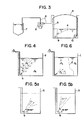
- Figs. 1a and 1b showing conventional filling. nozzles
- numeral 1 designates a filling nozzle
- numeral 2 designates the issuing direction or the axis of injection from each nozzle tip.
- Fig. 2 shows by the dotted lines the behaviour of the jet of gas resulting when a second LNG 5 of a different composition is introduced through the filling nozzle of Fig. 1b which is hung down into a storage tank 3 storing a first LNG 4 which was introduced preliminarily.
- Fig. 1 designates a filling nozzle
- numeral 2 designates the issuing direction or the axis of injection from each nozzle tip.
- Fig. 2 shows by the dotted lines the behaviour of the jet of gas resulting when a second LNG 5 of a different composition is introduced through the filling nozzle of Fig. 1b which is hung down into a storage tank 3 storing a first LNG 4 which was introduced preliminarily.
- Fig. 3 shows a flow diagram for explaining a basic example of the method according to the invention, in which LNG is introduced into a storage tank 3 from an LNG transport ship 7 via a filling line pipe 8. More specifically, a filling nozzle 6 is hung down into the preliminarily stored LNG 4 in the storage tank 3 and LNG 5 having a different density is introduced into the storage tank 3 via the filling nozzle 6. In this case, from the standpoint of improving the effect of this invention it is desirable to arrange a pressure pump 9 in the line pipe 8 so as to increase the feeding rate of the LNG 5.
- Numeral 15 designates a submerged pump for delivering the gas to the outside of the storage tank 3.
- the second liquefied gas of the density ⁇ c swallows up the first liquefied gas of the density ⁇ h so that the first and the second liquefied gases are stirred up and mixed during the introduction.
- the injection angle 0 of the filling nozzle 6 is less than 60°, as shown in Fig. 5a, the angle of jet is too small so that the resulting jet of gas may fail to reach or come near to the free surface or the jet of gas may strike against the side walls of the storage tank with the resulting deterioration of the swallow-up, thus deteriorating the effect of the nozzle.
- the issuing angle is not proper, there is the disadvantage of causing a density distribution in the following manner.
- the jet stream of the second liquefied gas decreases its flow velocity in the first liquefied gas and thus the second liquefied gas is partially distributed within the storage tank without sufficiently swallowing up the first liquefied gas.
- the gases are stored in such a manner that the lighter second liquefied gas floats to the surface and the introduction and filling of the second liquefied gas is completed without the second liquefied gas being sufficiently mixed with the heavier first liquefied gas as shown in Fig. 6 upon completion of the introduction.
- the densities ⁇ c and ⁇ h result in the formation of a density distribution / and this results in the formation of strata.
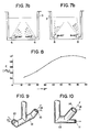
- the issuing angle from the nozzle tip of the filling nozzle is selected 60° ⁇ 8, and Fig. 5b shows the manner of mixing resulting from the use of the filling nozzle in accordance with this intention of the invention. It is also shown that where a plurality of the filling nozzles are used as in the cases of Figs. 7a and 7b, if the issuing angle is ⁇ 60° as in the cases of Figs. 5a and 5b, the resulting mixing effect is insufficient and that an excellent mixing effect is ensured with the intended issuing angle of 60° ⁇ 8 in accordance with the invention.
- the resulting issuing height h is determined in accordance with the nozzle jet diameter, the density difference and the flow rate with the angle 8 as a parameter.
- the height h can be said to be directly proportional to a quantity H having a unit of length and determined in accordance with three physical quantities including the nozzle jet diameter, the density difference and the flow rate and it has been confirmed experimentally by the inventors, etc., that its proportionality constant C varies with the angle 8 as shown in Fig. 8. It will be seen from the experimental results in Fig.
- the rate of rise in the height of jet increases with increase in the angle 8 when the angle 8 is in the range from 0 to 60°, that the rate of rise remains substantially constant when the angle ⁇ is in the range from over 60° to 80° and that the rate of rise decreases when the angle ⁇ reaches 90°.
- the most desirable range of A is from over 60° to 80° and the effect of the nozzle deteriorates when the angle 8 reaches 90°.
- the angle 8 is in the range of 60° ⁇ A ⁇ 90°. This can be conceived to be attributable to the fact that the efficiency of mixing in the vertical direction increases with increase in the height of jet of gas.
- Fig. 9 is a schematic perspective view of a filling nozzle which is suitable for use in performing a first embodiment of the method according to the invention.
- numeral 12 designates a filling nozzle proper, and 10 nozzle jet tips whose issuing angle has an elevation angle in the range 60° ⁇ 90° for the previously mentioned reasons.
- Fig. 10 is a schematic perspective view of another filling nozzle which is suitable for use in performing a second embodiment of the method according to the invention.
- numeral 13 designates a filling nozzle proper, and 14 a main nozzle whose issuing angle has an elevation angle 8 of 60° ⁇ e ⁇ 90° for the reasons mentioned previously.
- Numeral 11 designates an auxiliary nozzle which is made integral with the main nozzle 14and communicating with the lower part thereof.
- the issuing angle 8 of the filling nozzle is selected in the range 60° ⁇ 8 ⁇ 90° for the reasons that if the angle 8 is less than 60°, the value of the previously mentioned proportionality constant C becomes insufficient so that the resulting jet of gas fails to reach or come near to the surface of the liquefied gas or the jet of gas directly strikes against the side walls of the storage tank thus failing to expect the desired stirring and mixing effect, and that if the angle A is 90° or over, the height of gas jet becomes as low as when the angle ⁇ is less than 60°.
- the most desirable angle A is in the range from 60° to 80°.
- the auxiliary nozzle 11 is provided for the reason that if the density of the LNG introduced preliminarily into the storage tank is higher than that of the LNG which is introduced later, there is the possibility of the higher density LNG being detained in the tank bottom portion thus causing the formation of strata, and this possibility is prevented by the auxiliary nozzle 11.
Landscapes
- Engineering & Computer Science (AREA)
- Mechanical Engineering (AREA)
- General Engineering & Computer Science (AREA)
- Filling Or Discharging Of Gas Storage Vessels (AREA)
Abstract
Description
- The present invention relates to a method for preventing any stratification of the liquefied gases within a storage tank, and more particularly the present invention relates to improvements in and relating to a method and apparatus for introducing liquefied gas into a storage tank whereby when the multi-component liquefied gases comprising different kinds of liquefied gas such as liquefied natural gas (LNG) or liquefied petroleum gas (LPG) are stored in the same storage tank, the liquefied gas already existing in the storage tank and the newly introduced liquefied gas are prevented from being formed into separate strata within the storage tank due to differences in composition, density, temperature or the like.
- With a multi-component liquefied gas, e.g., LNG, it is well known in the art that the gases of different origins differ in composition and density from one another and the same applies to those from the same origin but extracted on different days. When such a multi-component liquefied gas is introduced into a storage tank from a transport ship or the like, while there will be no problem if the storage tank is filled with the gases of the same composition (those of the same origin and the same extraction date), if the remaining quantity of the previously introduced gas is small so that the storage tank has a space in surplus and thus a new supply of liquefied gas of a different composition or temperature is introduced into the storage tank, the heavy and light gases do not mix together due to differences in density and these gases are formed into vertically separated strata. The formation of these strata may sometimes cause a dangerous phenomenon which is known as a roll over phenomenon.
- The roll over phenomenon is one in which when multi-component liquefied gases which are different in composition and hence in density are contained in the same storage tank as mentioned previously, a stratum of higher density gas and a stratum of lower density gas will be formed as vertically separate strata; in the case of for example LNG liquefied at a very low temperature of -162°C, naturally there is a heat input through the outer walls of the storage tank so that due to the nature of the boundary surface of the vertically formed two strata that it is stable and its amount of heat transfer is small, the heat is accumulated in the lower stratum of the lower density liquefied gas and the thus accumulated heat energy is rapidly dispersed in the form of evaporation of a large quantity of the liquid. As a result, there is the danger of the inner pressure exceeding the control range of the storage tank inner pressure and becoming higher than the designed limit pressure.
- The density of LNG differs depending on the place of origin, that is, the density of LNG from Alaska is 424 Kg/m3, that of LNG from Brunei is 473 Kg/m3 and so on. If such .LNGs having different densities are introduced into the same storage tank, a vertical stratification will be caused by the differences in density and the above-mentioned roll over phenomenon may sometimes be caused. Thus, the usual practice to prevent this phenomenon has been such that LNG of different origins are stored in separate storage tanks and thus even the amount of the stored gas is as small as about one fifth of its holding capacity thus leaving a sufficient space in surplus, any LNG having a different composition and hence a different density will never be introduced into the storage tank. In other words, if the previously introduced liquefied gas is in excess of about 1/5 of the holding capacity of the storage tank, any other LNG having a different composition is not introduced into the storage tank and the remaining space is left unused. While this prevents the occurrence of any roll over phenomenon, the present situation is such that the number of storage tanks installed at a harbor or along the coast is in excess of the required number exceeding the actual holding capacity so that not only a vast plot of ground is required but also the cost amounts to a huge sum due to the installation of refrigerating equipment for maintenance of the facilities.
- Under these circumstances, as an anti-stratification measure, an attempt has heretofore been made such that when the amount of LNG contained in a storage tank is considerably less than its holding capacity, a filling nozzle is introduced into the LNG and LNG of a different composition is introduced to stir up and mix the two. The conventional filling nozzle used in this attempt has not been designed in consideration of mixing the liquefied gases having large differences in density and thus the jet of gas issued from the nozzle has failed to reach the free surface of the LNG within the storage tank thus making it impossible to stir up and mix the LNGs having large differences in density.
- Patent document DE-B-1271579 describes a tanker ship liquefied gas tank having an external circulation loop including a pump operative to circulate the existing liquefied gas when a predetermined temperature difference is detected between upper and lower zones in the tank. The liquefied gas is withdrawn at tank floor level and re-introduced through nozzles positioned near the floor and near a side wall and oriented obliquely upwardly directly towards the nearer side wall.
- An object of the present invention is to overcome the foregoing deficiencies in the prior art and to prevent any stratification of multi-component system liquefied gases such as LNG or LPG within a storage tank due to differences in composition and thereby to prevent the occurrence of a roll over phenomenon.
- In accordance with one form of the present invention, there is provided a method of introducing a second liquefied gas into a storage tank, which is partially full with a first liquefied gas, said second liquefied gas having a different density from said first liquefied gas and being miscible therewith;
- said method being consisting in:
- introducing said second liquefied gas through a nozzle positioned near the floor and near a side wall of said tank (known per se);
- said nozzle being oriented towards the centre of the tank to form a jet stream of said second liquefied gas;
- said jet stream issuing from said nozzle upwardly and towards the centre of the tank at an angle of elevation in the range between 60° and 90°; and
- said jet stream reaching or substantially reaching a free surface of liquefied gas in said tank without directly impinging on the side walls of the tank.
- In accordance with another form of the invention, there is provided apparatus for introducing a second liquefied gas into a storage tank which is partially full with a first liquefied gas, said second liquefied gas having a different density from said first liquefied gas and being miscible therewith, comprising
- a nozzle positioned near the floor and near a side wall of said tank for introduction of said second liquefied gas (known per se); characterized in that
- said nozzle is directed obliquely upwardly and oriented towards the centre of the tank to form a jet stream of said second liquefied gas upwardly towards the centre of the tank at an angle of elevation in the range between 60° and 90° to reach or substantially reach a free surface of liquefied gas in said tank without directly impinging on the side walls of the tank.
- The apparatus may be further characterized by an auxiliary nozzle positioned below said first-mentioned nozzle and directed towards a central portion of the floor of the storage tank to form a secondary jet stream of said second liquefied gas simultaneously with said first-mentioned jet stream, said secondary jet stream being relatively small in quantity.
- The auxiliary nozzle arrangement can be advantageously used particularly in cases where a newly introduced and issued liquefied gas is lower in density than the liquefied gas already existing in the storage tank. In this case, the issuing angle 0 of the main jet of liquefied gas is selected within a
range 60°<eZ80°. - The effect of utilization of the present invention is to stir up and to mix the fresh supply of liquefied gas from the filling nozzle and the previously stored liquefied gas at the time of filling, with the result that the prevention of stratification is ensured even in the case of the multi-component system liquefied gases having large differences in density, and the occurrence of the roll over phenomenon is thereby prevented.
- Further, while in the past the introduction of any replenishing supply of liquefied gas of a different composition is avoided in order to prevent the occurrence of stratification and roll over phenomenon, even if a storage tank is only partially full, in accordance with the method of this invention the introduction of a new supply of liquefied gas having a different density is possible for replenishing purposes. Thus, the storage tank can be filled with such liquefied gases up to its holding capacity and effective utilization of the storage tank is ensured. Therefore, the present invention greatly contributes to industrial efficiency.
- Embodiments of the invention will now be described, by way of example, with reference to the accompanying drawings, in which:
- Figs. 1a a and 1b are schematic views of conventional filling nozzles.
- Fig. 2 is a schematic diagram showing the manner in which a jet of gas is issued from the filling nozzle of Fig. 1b.
- Fig. 3 is a basic flow diagram showing the use of a filling nozzle according to the present invention.
- Fig. 4 is a diagram showing the flow conditions of the liquefied gases within a storage tank into which the liquefied gas having a different density is issued in accordance with the invention.
- Fig. 5 is a diagram showing the flow condition of the liquefied gas in a case where the issuing angle 8:560'.
- Fig. 5b is a diagram showing the flow condition of the liquefied gas in another case where the issuing angle θ>60°.
- Fig. 6 is a diagram for explaining the formation of strata due to the differences in density of the gases.
- Fig. 7a is a diagram similar to Fig. 5a but using two of the filling nozzle of Fig. 5a.
- Fig. 7b is a diagram similar to Fig. 5b but using two of the filling nozzle of Fig. 5b.
- Fig. 8 is a graph showing the relation between the issuing angle of the filling nozzle and the height of jet stream.
- Figs. 9 and 10 are schematic perspective views showing preferred forms of the filling nozzle used with the present invention.
- Prior to a detailed description of the invention, the prior art will be described briefly with reference to Figs. 1 and 2.
- In Figs. 1a and 1b showing conventional filling. nozzles, numeral 1 designates a filling nozzle and
numeral 2 designates the issuing direction or the axis of injection from each nozzle tip. Fig. 2 shows by the dotted lines the behaviour of the jet of gas resulting when asecond LNG 5 of a different composition is introduced through the filling nozzle of Fig. 1b which is hung down into astorage tank 3 storing afirst LNG 4 which was introduced preliminarily. As will be seen from Fig. 2, due to the issuing angle of the conventional filling nozzle being directed in a horizontal direction parallel to the bottom surface of thestorage tank 3, while the gases may be stirred up and mixed together in cases where the initial depth of thefirst LNG 4 is small or the density difference of the introducedsecond LNG 5 is relatively small, the jet of gas issued from thenozzle tip 2 cannot reach or come near to the free surface of the previously storedfirst LNG 4 if the initial depth is large or the density difference is large. Thus, in such a case, when the second LNG is introduced into the storage tank, the stirring and mixing of the upper and lower gases cannot be effected satisfactorily and the formation of strata is still unavoidable. - Fig. 3 shows a flow diagram for explaining a basic example of the method according to the invention, in which LNG is introduced into a
storage tank 3 from an LNG transport ship 7 via afilling line pipe 8. More specifically, a fillingnozzle 6 is hung down into the preliminarily storedLNG 4 in thestorage tank 3 andLNG 5 having a different density is introduced into thestorage tank 3 via thefilling nozzle 6. In this case, from the standpoint of improving the effect of this invention it is desirable to arrange a pressure pump 9 in theline pipe 8 so as to increase the feeding rate of theLNG 5.Numeral 15 designates a submerged pump for delivering the gas to the outside of thestorage tank 3. - The principle of preventing stratification of the multi-component system liquefied gases in a storage tank in accordance with the invention will now be described. Where the storage tank already contains a first multi-component liquefied gas such as LNG in an amount corresponding to about 1/5 to 2/3 of its holding capacity and thus there is still a surplus space, if a second LNG which is different in composition or density from the first LNG within the storage tank is introduced into the tank, that is, ifthe density ρc of the second liquefied gas is different from the density ρh of the first liquefied gas which was previously stored in the storage tank, as shown in Fig. 4, the second liquefied gas of the density ρc swallows up the first liquefied gas of the density ρh so that the first and the second liquefied gases are stirred up and mixed during the introduction. If the injection angle 0 of the filling
nozzle 6 is less than 60°, as shown in Fig. 5a, the angle of jet is too small so that the resulting jet of gas may fail to reach or come near to the free surface or the jet of gas may strike against the side walls of the storage tank with the resulting deterioration of the swallow-up, thus deteriorating the effect of the nozzle. In other words, if the issuing angle is not proper, there is the disadvantage of causing a density distribution in the following manner. - For instance, where the densities ρc and ph are ρc<ρh and the initial depth of the first liquefied gas with the higher density ph is relatively small, if the issuing angle θ of the second liquefied gas with the density ρc has an elevation angle of less than 60°, the jet stream of the second liquefied gas decreases its flow velocity in the first liquefied gas and thus the second liquefied gas is partially distributed within the storage tank without sufficiently swallowing up the first liquefied gas. As a result, the gases are stored in such a manner that the lighter second liquefied gas floats to the surface and the introduction and filling of the second liquefied gas is completed without the second liquefied gas being sufficiently mixed with the heavier first liquefied gas as shown in Fig. 6 upon completion of the introduction. Thus, the densities ρc and ρh result in the formation of a density distribution / and this results in the formation of strata.
- In accordance with the present invention, the issuing angle from the nozzle tip of the filling nozzle is selected 60°<8, and Fig. 5b shows the manner of mixing resulting from the use of the filling nozzle in accordance with this intention of the invention. It is also shown that where a plurality of the filling nozzles are used as in the cases of Figs. 7a and 7b, if the issuing angle is θ≤60° as in the cases of Figs. 5a and 5b, the resulting mixing effect is insufficient and that an excellent mixing effect is ensured with the intended issuing angle of 60°<8 in accordance with the invention.
- Where a first liquid having a uniform density is contained in a storage tank and a second liquid having a higher density is issued into the first liquid upwardly with an
angle 8, the resulting issuing height h is determined in accordance with the nozzle jet diameter, the density difference and the flow rate with theangle 8 as a parameter. As a result, the height h can be said to be directly proportional to a quantity H having a unit of length and determined in accordance with three physical quantities including the nozzle jet diameter, the density difference and the flow rate and it has been confirmed experimentally by the inventors, etc., that its proportionality constant C varies with theangle 8 as shown in Fig. 8. It will be seen from the experimental results in Fig. 8 that the rate of rise in the height of jet increases with increase in theangle 8 when theangle 8 is in the range from 0 to 60°, that the rate of rise remains substantially constant when the angle θ is in the range from over 60° to 80° and that the rate of rise decreases when the angle θ reaches 90°. Thus, the most desirable range of A is from over 60° to 80° and the effect of the nozzle deteriorates when theangle 8 reaches 90°. Thus, in order to achieve the desired effect of the invention it is necessary that theangle 8 is in the range of 60°<A<90°. This can be conceived to be attributable to the fact that the efficiency of mixing in the vertical direction increases with increase in the height of jet of gas. - Fig. 9 is a schematic perspective view of a filling nozzle which is suitable for use in performing a first embodiment of the method according to the invention. In the Figure, numeral 12 designates a filling nozzle proper, and 10 nozzle jet tips whose issuing angle has an elevation angle in the
range 60°<θ<90° for the previously mentioned reasons. Fig. 10 is a schematic perspective view of another filling nozzle which is suitable for use in performing a second embodiment of the method according to the invention. In the Figure, numeral 13 designates a filling nozzle proper, and 14 a main nozzle whose issuing angle has anelevation angle 8 of 60°<e<90° for the reasons mentioned previously. Numeral 11 designates an auxiliary nozzle which is made integral with the main nozzle 14and communicating with the lower part thereof. - Then, in accordance with the present invention the issuing
angle 8 of the filling nozzle is selected in therange 60°<8<90° for the reasons that if theangle 8 is less than 60°, the value of the previously mentioned proportionality constant C becomes insufficient so that the resulting jet of gas fails to reach or come near to the surface of the liquefied gas or the jet of gas directly strikes against the side walls of the storage tank thus failing to expect the desired stirring and mixing effect, and that if the angle A is 90° or over, the height of gas jet becomes as low as when the angle θ is less than 60°. - Thus, the most desirable angle A is in the range from 60° to 80°. On the other hand, the auxiliary nozzle 11 is provided for the reason that if the density of the LNG introduced preliminarily into the storage tank is higher than that of the LNG which is introduced later, there is the possibility of the higher density LNG being detained in the tank bottom portion thus causing the formation of strata, and this possibility is prevented by the auxiliary nozzle 11.
Claims (4)
Priority Applications (2)
| Application Number | Priority Date | Filing Date | Title |
|---|---|---|---|
| EP19810305689 EP0081012B1 (en) | 1981-12-02 | 1981-12-02 | Method and apparatus for preventing stratification of liquefied gases in a storage tank |
| DE8181305689T DE3176639D1 (en) | 1981-12-02 | 1981-12-02 | Method and apparatus for preventing stratification of liquefied gases in a storage tank |
Applications Claiming Priority (1)
| Application Number | Priority Date | Filing Date | Title |
|---|---|---|---|
| EP19810305689 EP0081012B1 (en) | 1981-12-02 | 1981-12-02 | Method and apparatus for preventing stratification of liquefied gases in a storage tank |
Publications (2)
| Publication Number | Publication Date |
|---|---|
| EP0081012A1 EP0081012A1 (en) | 1983-06-15 |
| EP0081012B1 true EP0081012B1 (en) | 1988-02-03 |
Family
ID=8188470
Family Applications (1)
| Application Number | Title | Priority Date | Filing Date |
|---|---|---|---|
| EP19810305689 Expired EP0081012B1 (en) | 1981-12-02 | 1981-12-02 | Method and apparatus for preventing stratification of liquefied gases in a storage tank |
Country Status (2)
| Country | Link |
|---|---|
| EP (1) | EP0081012B1 (en) |
| DE (1) | DE3176639D1 (en) |
Families Citing this family (2)
| Publication number | Priority date | Publication date | Assignee | Title |
|---|---|---|---|---|
| CN102878425B (en) * | 2012-10-23 | 2014-01-22 | 张家港富瑞特种装备股份有限公司 | Device for avoiding liquid layering in liquefied natural gas storage tank |
| FR3081967B1 (en) * | 2018-05-30 | 2020-12-25 | Gaztransport Et Technigaz | LIQUEFIED GAS STORAGE DEVICE |
Family Cites Families (1)
| Publication number | Priority date | Publication date | Assignee | Title |
|---|---|---|---|---|
| DE1271579B (en) * | 1960-03-07 | 1968-06-27 | California Texas Oil Corp | Device for influencing the vapor pressure in liquid gas tanks on tankers |
-
1981
- 1981-12-02 EP EP19810305689 patent/EP0081012B1/en not_active Expired
- 1981-12-02 DE DE8181305689T patent/DE3176639D1/en not_active Expired
Also Published As
| Publication number | Publication date |
|---|---|
| EP0081012A1 (en) | 1983-06-15 |
| DE3176639D1 (en) | 1988-03-10 |
Similar Documents
| Publication | Publication Date | Title |
|---|---|---|
| KR101672606B1 (en) | Device for collecting and separating aqueous and/or oily liquids and cryogenic liquid | |
| US2459227A (en) | Underground reservoir for the storage of liquefied gases | |
| US4470402A (en) | Apparatus for storing heavy hydrocarbon oil and vessel therefor | |
| US4641690A (en) | Method and apparatus for preventing stratification of liquefied gases in a storage tank | |
| US3472033A (en) | Fluid storage apparatus | |
| US3106071A (en) | System for filling closed containers with volatile liquids | |
| FI66480B (en) | FOERFARANDE FOER FYLLANDE AV EN TERMISKT ISOLERAD TANK MED FLYTANDE GAS OCH TERMISKT ISOLERAD TANK AV FLYTANDE GAS | |
| US4343621A (en) | Process for the production of aqueous solutions of sodium chloride from rock salt | |
| EP0081012A1 (en) | Method and apparatus for preventing stratification of liquefied gases in a storage tank | |
| US12600444B2 (en) | Method for controlling the trim of a transport ship without seawater ballast | |
| US20140238533A1 (en) | Efficiently effectively inserting inert gases into the entire volumes and ullage spaces of ships' steel ballast tanks to retard interior corrosion | |
| US3605774A (en) | Maritime apparatus utilizable as a hydrocarbon reservoir | |
| JPS58191399A (en) | Stratification preventive method of liquefied natural gas in tank | |
| US3850206A (en) | Foamed vapor barrier | |
| EP0002372B1 (en) | Subterranean storage pool for liquids and method for using the same | |
| JP2733858B2 (en) | Cryogenic tank rollover prevention device | |
| CN112673206B (en) | Liquefied gas storage device | |
| KR101249401B1 (en) | A Intermediate LNG Storage Tank to reject boil-off gas | |
| JPH09203500A (en) | Delayering device for liquid in storage tank | |
| US5125439A (en) | Method for controlling vapor emissions during loading of tankers | |
| US2237052A (en) | Dispensing and mixing apparatus for liquefied gas | |
| JP2000193196A (en) | Stratification prevention device in low temperature liquefied gas tank | |
| US2013685A (en) | Art of handling volatile liquids | |
| US2632466A (en) | Storage tank construction | |
| KR102629030B1 (en) | Liquefied Gas Loading apparatus |
Legal Events
| Date | Code | Title | Description |
|---|---|---|---|
| PUAI | Public reference made under article 153(3) epc to a published international application that has entered the european phase |
Free format text: ORIGINAL CODE: 0009012 |
|
| AK | Designated contracting states |
Designated state(s): DE FR GB IT NL SE |
|
| 17P | Request for examination filed |
Effective date: 19830722 |
|
| ITF | It: translation for a ep patent filed | ||
| GRAA | (expected) grant |
Free format text: ORIGINAL CODE: 0009210 |
|
| AK | Designated contracting states |
Kind code of ref document: B1 Designated state(s): DE FR GB IT NL SE |
|
| REF | Corresponds to: |
Ref document number: 3176639 Country of ref document: DE Date of ref document: 19880310 |
|
| ET | Fr: translation filed | ||
| PLBI | Opposition filed |
Free format text: ORIGINAL CODE: 0009260 |
|
| 26 | Opposition filed |
Opponent name: LINDE AKTIENGESELLSCHAFT, WIESBADEN Effective date: 19881103 |
|
| NLR1 | Nl: opposition has been filed with the epo |
Opponent name: LINDE AG |
|
| PGFP | Annual fee paid to national office [announced via postgrant information from national office to epo] |
Ref country code: GB Payment date: 19891130 Year of fee payment: 9 |
|
| PGFP | Annual fee paid to national office [announced via postgrant information from national office to epo] |
Ref country code: FR Payment date: 19891211 Year of fee payment: 9 |
|
| PGFP | Annual fee paid to national office [announced via postgrant information from national office to epo] |
Ref country code: SE Payment date: 19891214 Year of fee payment: 9 |
|
| ITTA | It: last paid annual fee | ||
| PGFP | Annual fee paid to national office [announced via postgrant information from national office to epo] |
Ref country code: NL Payment date: 19891231 Year of fee payment: 9 |
|
| PGFP | Annual fee paid to national office [announced via postgrant information from national office to epo] |
Ref country code: DE Payment date: 19900131 Year of fee payment: 9 |
|
| PG25 | Lapsed in a contracting state [announced via postgrant information from national office to epo] |
Ref country code: GB Effective date: 19901202 |
|
| PG25 | Lapsed in a contracting state [announced via postgrant information from national office to epo] |
Ref country code: SE Effective date: 19901203 |
|
| PG25 | Lapsed in a contracting state [announced via postgrant information from national office to epo] |
Ref country code: NL Effective date: 19910701 |
|
| GBPC | Gb: european patent ceased through non-payment of renewal fee | ||
| NLV4 | Nl: lapsed or anulled due to non-payment of the annual fee | ||
| PG25 | Lapsed in a contracting state [announced via postgrant information from national office to epo] |
Ref country code: FR Effective date: 19910830 |
|
| PG25 | Lapsed in a contracting state [announced via postgrant information from national office to epo] |
Ref country code: DE Effective date: 19910903 |
|
| REG | Reference to a national code |
Ref country code: FR Ref legal event code: ST |
|
| RDAG | Patent revoked |
Free format text: ORIGINAL CODE: 0009271 |
|
| STAA | Information on the status of an ep patent application or granted ep patent |
Free format text: STATUS: PATENT REVOKED |
|
| 27W | Patent revoked |
Effective date: 19911215 |
|
| EUG | Se: european patent has lapsed |
Ref document number: 81305689.2 Effective date: 19910910 |
|
| APAH | Appeal reference modified |
Free format text: ORIGINAL CODE: EPIDOSCREFNO |