EP0080888B1 - Electro-mechanical direct drive valve servo system with rotary to linear valve drive mechanism - Google Patents
Electro-mechanical direct drive valve servo system with rotary to linear valve drive mechanism Download PDFInfo
- Publication number
- EP0080888B1 EP0080888B1 EP82306344A EP82306344A EP0080888B1 EP 0080888 B1 EP0080888 B1 EP 0080888B1 EP 82306344 A EP82306344 A EP 82306344A EP 82306344 A EP82306344 A EP 82306344A EP 0080888 B1 EP0080888 B1 EP 0080888B1
- Authority
- EP
- European Patent Office
- Prior art keywords
- valve
- axial
- cam
- plunger
- rotational axis
- Prior art date
- Legal status (The legal status is an assumption and is not a legal conclusion. Google has not performed a legal analysis and makes no representation as to the accuracy of the status listed.)
- Expired
Links
- 230000007246 mechanism Effects 0.000 title description 44
- 239000012530 fluid Substances 0.000 claims description 20
- 230000007935 neutral effect Effects 0.000 claims description 16
- 125000006850 spacer group Chemical group 0.000 claims description 9
- 230000004323 axial length Effects 0.000 claims description 4
- 230000036316 preload Effects 0.000 claims description 4
- 230000000452 restraining effect Effects 0.000 claims description 4
- 230000000694 effects Effects 0.000 description 8
- RZVHIXYEVGDQDX-UHFFFAOYSA-N 9,10-anthraquinone Chemical compound C1=CC=C2C(=O)C3=CC=CC=C3C(=O)C2=C1 RZVHIXYEVGDQDX-UHFFFAOYSA-N 0.000 description 6
- 230000002411 adverse Effects 0.000 description 2
- 230000009977 dual effect Effects 0.000 description 2
- 230000003416 augmentation Effects 0.000 description 1
- 230000003190 augmentative effect Effects 0.000 description 1
- 238000004891 communication Methods 0.000 description 1
- 238000010276 construction Methods 0.000 description 1
- 239000012729 immediate-release (IR) formulation Substances 0.000 description 1
- 238000012544 monitoring process Methods 0.000 description 1
- 230000002265 prevention Effects 0.000 description 1
- 238000009877 rendering Methods 0.000 description 1
- 230000000717 retained effect Effects 0.000 description 1
Images

Classifications
-
- F—MECHANICAL ENGINEERING; LIGHTING; HEATING; WEAPONS; BLASTING
- F15—FLUID-PRESSURE ACTUATORS; HYDRAULICS OR PNEUMATICS IN GENERAL
- F15B—SYSTEMS ACTING BY MEANS OF FLUIDS IN GENERAL; FLUID-PRESSURE ACTUATORS, e.g. SERVOMOTORS; DETAILS OF FLUID-PRESSURE SYSTEMS, NOT OTHERWISE PROVIDED FOR
- F15B13/00—Details of servomotor systems ; Valves for servomotor systems
- F15B13/02—Fluid distribution or supply devices characterised by their adaptation to the control of servomotors
- F15B13/04—Fluid distribution or supply devices characterised by their adaptation to the control of servomotors for use with a single servomotor
- F15B13/0401—Valve members; Fluid interconnections therefor
- F15B13/0402—Valve members; Fluid interconnections therefor for linearly sliding valves, e.g. spool valves
-
- F—MECHANICAL ENGINEERING; LIGHTING; HEATING; WEAPONS; BLASTING
- F15—FLUID-PRESSURE ACTUATORS; HYDRAULICS OR PNEUMATICS IN GENERAL
- F15B—SYSTEMS ACTING BY MEANS OF FLUIDS IN GENERAL; FLUID-PRESSURE ACTUATORS, e.g. SERVOMOTORS; DETAILS OF FLUID-PRESSURE SYSTEMS, NOT OTHERWISE PROVIDED FOR
- F15B13/00—Details of servomotor systems ; Valves for servomotor systems
- F15B13/02—Fluid distribution or supply devices characterised by their adaptation to the control of servomotors
- F15B13/04—Fluid distribution or supply devices characterised by their adaptation to the control of servomotors for use with a single servomotor
- F15B13/044—Fluid distribution or supply devices characterised by their adaptation to the control of servomotors for use with a single servomotor operated by electrically-controlled means, e.g. solenoids, torque-motors
-
- F—MECHANICAL ENGINEERING; LIGHTING; HEATING; WEAPONS; BLASTING
- F15—FLUID-PRESSURE ACTUATORS; HYDRAULICS OR PNEUMATICS IN GENERAL
- F15B—SYSTEMS ACTING BY MEANS OF FLUIDS IN GENERAL; FLUID-PRESSURE ACTUATORS, e.g. SERVOMOTORS; DETAILS OF FLUID-PRESSURE SYSTEMS, NOT OTHERWISE PROVIDED FOR
- F15B18/00—Parallel arrangements of independent servomotor systems
-
- F—MECHANICAL ENGINEERING; LIGHTING; HEATING; WEAPONS; BLASTING
- F16—ENGINEERING ELEMENTS AND UNITS; GENERAL MEASURES FOR PRODUCING AND MAINTAINING EFFECTIVE FUNCTIONING OF MACHINES OR INSTALLATIONS; THERMAL INSULATION IN GENERAL
- F16H—GEARING
- F16H23/00—Wobble-plate gearings; Oblique-crank gearings
- F16H23/04—Wobble-plate gearings; Oblique-crank gearings with non-rotary wobble-members
- F16H23/08—Wobble-plate gearings; Oblique-crank gearings with non-rotary wobble-members connected to reciprocating members by connecting-rods
-
- Y—GENERAL TAGGING OF NEW TECHNOLOGICAL DEVELOPMENTS; GENERAL TAGGING OF CROSS-SECTIONAL TECHNOLOGIES SPANNING OVER SEVERAL SECTIONS OF THE IPC; TECHNICAL SUBJECTS COVERED BY FORMER USPC CROSS-REFERENCE ART COLLECTIONS [XRACs] AND DIGESTS
- Y10—TECHNICAL SUBJECTS COVERED BY FORMER USPC
- Y10T—TECHNICAL SUBJECTS COVERED BY FORMER US CLASSIFICATION
- Y10T74/00—Machine element or mechanism
- Y10T74/18—Mechanical movements
- Y10T74/18056—Rotary to or from reciprocating or oscillating
- Y10T74/18296—Cam and slide
- Y10T74/18336—Wabbler type
Definitions
- This invention relates generally to a fluid servo system, and more particularly to an aircraft flight control servo system. More specifically, this invention relates to an electro-mechanical control system, and still more specifically to a valve drive mechanism for use in such a system that couples a rotary motion control input, and auxiliary inputs, to a sliding-type servo valve.
- Fluid servo systems are used for many purposes, one being to position the flight control surfaces of an aircraft.
- system redundancy is desired to achieve increased reliability in various modes of operation, such as in the control augmentation or electrical mode.
- plural redundant electro-hydraulic valves have been used in conjunction with plural redundant servo actuators to assure proper position control of the control surface in the case of failure of one of the valves and/or servo actuators.
- Such added redundancy results in a complex system with many additional electrical and hydraulic elements necessary to perform the various sensing, equalization, timing and other control functions.
- the system's complexity has reduced overall reliability, has increased package size and cost, and has imposed added requirements on the associated control electronics.
- electro-hydraulic control system An alternative approach to the electro-hydraulic control system is the electro-mechanical control system wherein a force motor is coupled directly and mechanically to the main control servo valve.
- system redundancy has been accomplished by mechanical summation of forces directly within the multiple coil motor as opposed to the conventional system where redundancy is achieved by hydraulic force summing using multiple electro-hydraulic valves. If one coil or its associated electronics should fail, its counterpart channel will maintain control while the failed channel is uncoupled and made passive.
- the force motor output is in the form of either linear or rotary motion.
- Linear motion obviously may be directly coupled to a sliding-type valve whereas rotary motion is more compatible with a rotary- type valve.
- the guide shaft extends into a guide slot therefor that constrains the guide shaft to arcuate movement in a plane passing through the rotating shaft's rotational axis. This accordingly causes the sleeve and guide shaft to wobble or nutate upon rotation of the rotating shaft.
- a linkage connected between the guide shaft and sliding valve provides for linear movement of the valve in response to the nutating movement of the sleeve and guide shaft.
- valve drive mechanism While the valve drive mechanism disclosed in U.S. Patent No. 3,636,779 may find particular utility in an ordinary vehicle, its use in an aircraft flight control system may not be particularly desirable for various reasons. For instance, the high resultant forces developed in the angular contact type bearing from the applied torsional moments limit the load carrying ability of the mechanism. Such high resultant forces also tend to spread apart the inner and outer races which has an adverse effect on the mechanism's .stiffness. Moreover, to achieve control of bearing backlash or preload, the angular contact bearing must be specially fabricated or selected with no adjustments being available therein. In addition, such mechanism utilizes a semiflexible linkage to avoid undesirable valve plunger side loads and associated friction, which further adversely affects the mechanism's stiffness and load carrying ability.
- the valve drive mechanism of U.S. Patent No. 3,636,779 includes a servo system for controlling a fluid output device.
- the servo system comprises a servo valve including a linearly movable valve element for selectively supplying high pressure fluid to the output device to control same and control input means for operating the servo valve.
- the control input means includes a rotary force motor that rotatably drives a first member about a rotational axis, said first member having an axial face inclined to the rotational axis.
- a second member is journaled on the first member for rotation relative to the first member, said second member having an axial face in axial alignment and bearing engagement with the axial face of the first member.
- a radial arm on the second member is restrained for movement in a plane parallel to the rotational axis and is connected to the valve element for linear movement of the valve element in response to nutating movement of the arm upon rotation of the first member by the force motor.
- servo system for controlling a fluid output device, comprising a servo valve including a linearly movable valve element for selectively supplying high pressure fluid to the output device to control same, and control input means for operating said servo valve, said control input means including a rotary force motor, a first member rotatably driven by said force motor about a rotational axis, said first member having an axial face inclined to said rotational axis, a second member journaled on said first member for rotation relative to said first member, said second member having an axial face in axial alignment and bearing engagement with said axial face of said first member, a radial arm on said second member, means for restraining said arm for movement in a plane parallel to said rotational axis, connecting means connecting said arm to said valve element for linear movement of said valve element in response to nutating movement of said arm upon rotation of said first member by said force motor, characterized in that said servo valve includes two linearly movable valve elements alternate
- Such a servo system finds particular utility in an aircraft control servo system where the servo valve controls the flow of high pressure fluid to an actuator connected to an aircraft flight control surface.
- a valve drive mechanism comprising a rotary input member which is connected to and rotatably driven by the rotary force motor, and which has an axial driving face inclined or canted to its rotational axis.
- the rotary member is rotatable with respect to a wobble member journaled thereon, which wobble member has an axial driven face axially aligned with and in bearing engagement with the axial face of the rotary member, whereby the wobble member is canted by the rotary member with respect to the rotational axis of the rotary member.
- An output arm on the wobble member extends radially thereof, and means are provided for restraining the output arm for movement in a plane parallel to the rotational axis of the rotary member and for connecting the output arm to the valve for linear movement of the valve in response to the nutating arcuate movement of the output arm upon rotation of the rotary member. Because the engaged axial faces of the rotary member and wobble member are in axial alignment, the bearing surfaces transmitting the applied torsional moment are aligned in the direction of the developed reaction forces whereby high loads can be supported and adequate stiffness obtained. Moreover, an essentially linear relationship exists between the rotary input motion and linear output motion of the mechanism over a desired working range of the valves. In addition, a wide range of valve stroke/force relationships may be readily achieved by changing the cant of the wobble member and/or effective length of the output arm.
- the valve drive mechanism includes a pair of axially spaced rotary members that are connected to the force motor for common rotation about an axis parallel to the line of movement of the sliding-type valve.
- a wobble member in the form of a disc or plate is located between commonly inclined axial faces of the rotary members and canted thereby with respect to such rotational axis.
- Disposed between the axially aligned and opposed faces of the rotary members and wobble member are thrust ball bearings which effect the bearing engagement therebetween.
- the opposed faces of the rotary members and wobble members are provided with cooperating circular grooves which receive and retain the ball bearings. In this manner, the wobble member and bearings are supported between and by the rotary members.
- the spacing between the rotary members is precisely set by a spacer positoned therebetween at assembly whereby bearing backlash and preload may be precisely controlled at assembly.
- the spacer preferably is lapped to precisely the correct axial length to achieve a lightly preloaded conditon without any backlash.
- the wobble member has a radially extending output arm which has a ball received in a socket in the linearly movable element of the valve whereby the arm is constrained for arcuate movement in a plane intersecting the line of movement of the valve element. Accordingly, rotation of the rotary member effects a nutating movement of the wobble member which movement effects linear movement of the valve element.
- the valve drive mechanism readily accommodates additional or auxiliary control inputs, such as braking and re-centering function inputs.
- one of the rotary members is provided with a V-shape cam slot and a friction brake surface both radially offset from the rotational axis of such members.
- a cam plunger is movable into the cam slot in response to said electrical system failure in the aircraft control servo system. Initial movement of the cam plunger releases a brake shoe which engages the brake surface on the rotary member to hold the drive mechanism in its then existing position. The cam plunger continues to move into engagement with the sloping walls of the cam slot at a predetermined controlled rate to center the drive mechanism. During re-centering, the brake holding friction is overcome.
- valve drive mechanism When the cam plunger is fully engaged, it is received in a sharply shouldered slot or detent at the vertex of the V-shape cam slot to lock the drive mechanism in its neutral or centered position. When so locked at its input end, the valve drive mechanism establishes a high mechanical "disadvantage" against any external forces that would tend to back-drive the drive mechanism, thereby providing excellent holding or reactive capability.
- the servo actuators 12 and 14 each have an inlet port 20 for connection with a source of high pressure hydraulic fluid and a return port 22 for connection with a hydraulic reservoir.
- the respective inlet and return ports of the servo actuators are connected to separate and independent hydraulic systems in the aircraft. In the event one of the hydraulic systemsfails or is shut down, the servo actuator coupled to the other still functioning hydraulic system may be operated to effect the position control function.
- a passage 24 connects the inlet port 20 to a check valve 26.
- the check valve 26 in turn is connected by a passage 28 to' a servo valve 30.
- Another passage 32 connects the return port 22 to the servo valve 30.
- the servo valve 30 includes a spool 34 which is longitudinally shiftable in a sleeve 36.
- the sleeve 36 in turn is longitudinally shiftable in a tubular insert 38 in the system housing 40.
- the spool and sleeve are divided into two fluidically isolated vaiving sections indicated generally at 42 and 44 in Fig. 1, which valving sections are associated respectively with the actuators 12 and 14 and the passages 28 and 32 thereof.
- Each valving section of the spool and sleeve is provided with suitable lands, grooves and passages such that either one of the spool or sleeve may be maintained at a nominal or centered position, and the other selectively shifted for selectively connecting the passages 28 and 32 of each servo actuator to passages 46 and 48 in the same servo actuator.
- the passages 46 and 48 of both servo actuators 12 and 14 are connected to the dual cylinder tandem actuator 16 which includes a pair of cylinders 50.
- the passages 46 and 48 of each servo actuator are connected to a corresponding one of the cylinders at opposite sides of the piston 52 therein. If desired, anti-cavitation valves may be provided as indicated in the passages 46 and 48.
- the pistons 52 of the cylinders 50 are interconnected by connecting rod 54 and further are connected by output rod 56 to the control element 18 through linkage 57.
- valving sections 42 and 44 which selectively connect one side of each cylinder 50 to a high pressure hydraulic fluid source and the other side to fluid return for effecting controlled movement of the output rod 56 either to the right or left as seen in Fig. 1.
- the other servo actuator will maintain control responsive to selective relative movement of the spool and sleeve.
- the relatively shiftable spool 34 and sleeve 36 provide for two separate operational modes for effecting the position control function.
- the spool for example, may be operatively associated with a manual operational mode while the sleeve is operatively associated with a control augmented or electrical operational mode.
- spool postioning may be effected through direct mechanical linkage to a control element in the aircraft cockpit.
- the spool may have a cylindrical socket 58 which receives a ball 60 at the end of a crank 62.
- the crank 62 may be connected by a suitable mechanical linkage system to the aircraft cockpit control element.
- the manual control mode will remain passive unless a failure renders the electrical mode inoperable.
- the spool 34 is held in a neutral or centered position while the sleeve 36 is con- trollably shifted to effect the positon control function.
- Controlled shifting of the valve sleeve 36 is effected by a valve drive assembly 63 including a rotary force motor 64 which is responsive to electrical command signals received from the aircraft cockpit.
- the force motor 64 preferably has redundant multiple parallel coils so that if one coil or its associated electronics should fail, its counterpart channel will maintain control.
- suitable failure monitoring circuitry is provided to detect when and which channel has failed, and to uncouple or render passive the failed channel.
- the force motor 64 can be seen to include a motor housing 66 which is secured to the system housing 40 that contains the servo valve 30.
- the motor stator 68 is fixed in the motor housing whereas the rotor 70 is journaled by bearings 72 and 74 in the motor housing.
- the bearings 72 and 74 are of the radial and thrust type and are slightly preloaded for prevention of axial and radial shifting of the rotor in the motor housing.
- the rotor 70 has a central axial bore in which the motor shaft 76 is fixed.
- the motor shaft 76 extends through the base plate 78 of the motor housing into a chamber 80 in the system housing 40.
- Suitable seals 82 are provided in the base plate 78 to preclude passage of hydraulic fluid from the chamber 80 into the interior of the motor 64.
- the shaft 76 of the force motor 64 is coupled to the servo valve sleeve 36 by a drive mechanism 84 which is contained within the chamber 80 in the system housing 40.
- the drive mechanism 84 includes a pair of rotary input members 86 and 88 which are secured on a tubular shaft extension 89 connected to the motor shaft 76 for rotation therewith about the shaft's rotational axis.
- the rotary members 86 and 88 are axially spaced apart by a spacer 90 and have opposed parallel axial end faces 92 and 94, respectively, which are commonly inclined or canted at an angle (other than 90°) to the rotational axis of the motor shaft as seen in Fig. 3.
- a disc or plate-like wobble member 96 Journaled between the axial faces 92 and 94 is a disc or plate-like wobble member 96 which has parallel axial end faces 98 and 100 respectively in bearing engagement with the faces 92 and 94 of the rotary members.
- Such bearing engagement preferably is obtained by annular ball thrust bearings 102 disposed between the opposed faces of the wobble plate and rotary members. The balls of the bearings are rceived and retained in circular grooves in the faces of the wobble plate and rotary members. In this manner, the wobble member and the bearings are supported between and by the rotary members.
- the drive mechanism 84 is maintained in the above described assembled relationship by dowel pins 104 which are press fitted in bores extending through the rotary member 86 and 88 and spacer 90. When so assembled, the rotary members are maintained in tight engagement with the spacer 90. It should be noted that by carefully selecting the thickness of the spacer i.e., the axial length of the spacer, such as by lapping its axial end faces, the bearing clearance or preload may be precisely set at a predetermined amount at assembly. Preferably, the spacer is lapped to precisely the correct axial length to achieve a slightly preloaded condition without backlash.
- the wobble member 96 can be seen in Fig. 2 to have a radially extending output arm 106. At the radially outermost end of the arm 106, a ball 108 is integrally formed or secured thereto. This ball is closely fitted in a cylindrical socket 110 provided in an axial extension 112 on the servo valve sleeve 36. Because the servo valve sleeve is restrained for liner movement along its longitudinal axis in the housing insert 38, which axis is parallel to the rotational axis of the rotary members 86 and 88, the output arm is constrained for arcuate movement in a plane parallel to such longitudinal axis of the sleeve.
- the wobble member 96 is restrained against rotation along with the rotary member 86 and 88 as the latter are rotated by the force motor shaft 76 in response to a command input to the force motor 64. Accordingly, the wobble member and arm 106 will nutate about an axis perpendicular to the longitudinal axis of the sleeve and also the rotational axis of the rotary members. During such movement of the arm, the ball 108 at the end thereof will bear against the sides of the socket 110 to generate a force along the longitudinal axis of the sleeve for effecting linear movement of such sleeve.
- the rise and fall of the ball during such arcuate movement will be accommodated by the socket, such ball sliding along the socket in a direction normal to the longitudinal axis of the sleeve.
- the output arm 106 may be provided with a guide ball 112 which is constrained by laterally spaced parallel guide lands 114 and 115 as illustrated in Fig. 5 wherein primed reference numerals designate elements corresponding generally to those indentified above by the same unprimed reference numerals.
- the guide lands 114 and 115 which may be fitted in the housing 40, extend in a direction parallel to the longitudinal axis of the valve sleeve 36, and accordingly constrain movement of the ball 112, and hence the output arm 106, against movement in any direction other than in a plain parallel to such axis.
- the guide lands 114 and 115 bear any developed lateral side loads and not the valve sleeve.
- a linear realtionship essentially exists between the rotary input motion of the drive motor shaft 76 and the linear motion of the valve sleeve 36 generally within plus or minus 40° of rotation of the motor shaft from a center or neutral position. It also should be noted that by changing the angle of inclination of the wobble member 96 with respect to the axis of the motor shaft and/or the effective radial length of the output arm 106, a wide range of valve stroke/force relationships may be achieved without redesign of the basic drive mechanism configuration and hence with a minimum of hardware changes.
- an auxiliary input to the drive mechanism 84 such as the valve centering and lock assembly designated generally by reference numeral 116 in Fig. 1 is provided for controlling failure transients and for positioning the servo valve sleeve 36 at its centered or neutral position.
- the centering and lock assembly 116 includes a cam plunger 118 which is biased by a plunger spring 119 to the left in Fig. 1.
- the cam plunger 118 includes pistons 120 and 122 which are positioned in cylinders 124 and 126.
- the cylinders 124 and 126 are in the form of inserts received in a bore in the housing 40 and are associated respectively with the servo actuators 12 and 14.
- the hydraulic circuitry in the servo actuators associated with each piston and cylinder is similar and for ease in description, like reference numerals will be used to identify corresponding elements of such circuitry.
- each cylinder 124, 126 is connected by a passage 134 to a solenoid-operated shut-off valve 136.
- a solenoid-operated shut-off valve 136 In the energized position of the shut-off valve 136, fluid communication is established between the passage 134 and a passage 138 that connects the shut-off valve to the passage 28.
- the shut-off valve When de-energized upon failure in the electrical operational mode, the shut-off valve connects the passage 134 to the return passage 32.
- each shut-off valve 136 supplies high pressure fluid to the left side of the respective cylinders 124, 126. This forces the respective pistons 120, 122 to the right which in turn forces the cam plunger 118 to the right against the plunger spring 119.
- a passage 142 is connected to the right side of each cylinder 124, 126 for returning fluid therein to the return passage 32 to permit such movement of the pistons to the right.
- each passage 134 is bifurcated into two passages 144 and 146.
- Each passage 144 is connected to the far left side of the respective cylinders 124, 126, and has therein a centering rate control or metering orifice 148 for a purpose which will become more apparent below.
- the other passage 146 is connected more centrally to the respective cylinder and is open to the left side of the respective pistons 120,122 only when the cam plunger 118 is in or near its retracted position.
- the cam plunger 118 at its left end has a rounded V-shaped nose 150 and a stop shoulder or collar 152 axially to the right of the nose.
- the stop collar 152 engages and restrains a brake shoe 154 mounted for sliding movement on the cam plunger.
- the brake shoe 154 is biased to the left by a brake spring 156 positioned between the brake shoe and the cylinder insert 124.
- the nose 150 and brake shoe 154 are adapted to engage respectively a cam slot 158 in the outer rotary member 88 and brake member 160 of the drive mechanism 84.
- the brake member 160 has an axially extending cylindrical portion 162 fitted into the interior of the tubular shaft extension 89.
- the brake member further has a radially extending brake plate 164 which is substantially radially offset from the rotational axis of the shaft extension 89.
- the plate 164 abuts the end of the tubular end portion of the outer rotary member 88 and is secured thereto for common rotation by pins 166.
- Such plate has an axially outer brake surface 168 adapted for frictional engagement with the brake shoe 154, and an opening or window 170 aligned with the cam slot 158 formed in the outer rotary member 88.
- the cam slot 158 is radially offset from the rotational axis of the rotary member 88 and opens axially in longitudinal alignment with the cam plunger 118.
- the cam slot has sloping side walls 172 which give the slot a V shape. At the vertex of the slot, the side walls slope sharply and substantially axially to form a sharply shouldered detent 174 having a shape generally corresponding to the shape of the nose 150 of the cam plunger.
- the detent is circumferentially positioned in the rotary member such that when the plunger nose is received and seated in the detent, the servo valve sleeve 36 will be in its centered or neutral positon and locked therein by reason of the sharp or axial shoulders of the detent that preclude the plunger nose from being cammed out of the detent.
- each shut-off valve 136 is energized. This supplies hydraulic pressure to the left side of each piston 120, 122 thereby retracting the cam plunger 118 to the rightto its retacted position seen in Fig. 1. As the cam plunger nears its retracted position, the stop collar 152 engages the brake shoe 154 and retracts it out of contact with the brake plate 164. Accordingly, the valve centering and lock assembly 116 is disengaged to allow controlled positioning orshifting ofthevalve sleeve 36 by the valve drive mechanism 84 in response to electrical command signals received from the aircraft cockpit.
- both shut-off valves 136 are de-energized. This connects the left side of the pistons to return pressure. Initially, high pressure fluid will fow out of the left side of each cylinder 124, 126 through the nonrestricted passage 146 to the return port 22 for initial rapid movement of the cam plunger 118 to the left in Fig. 1, such movement being effected by plunger spring 119. This initial rapid movement causes immediate release of the brake shoe 154which is urged by the brake spring 156 into friction engagement with the brake plate 164. The brake holding friction will maintain the drive mechanism, and hence the servo valve, in its then existing position.
- the drive mechanism 84 of the present invention is of relatively simple construction while providing many advantages.
- the drive mechanism exhibits very good linearity between the rotary motion of the force motor 64 and the sliding motion at the servo valve sleeve 36 over a desired working range of the valve.
- the drive mechanism provides gearing between the force motor output and valve input which easily accommodates gearing changes by relatively simple hardware changes such that a wide range of valve stroke/force relationships may be achieved without re-design of the basic motor/valve configurations. For instance, by changing the angle of the canted faces of the rotary members 86 and 88 with respect to their rotational axis and/or the radial length of the output arm 106, a wide range of gearing may be readily obtained.
- the drive mechanism with its inherent gearing provides convenient means for accommodating other control inputs, such as the described braking and recentering device, while taking advantage of the gearing force ratio. This reduces the complexity and size of such other control inputs. That is, the braking and centering functions may be accomplished at the input end of the gearing thereby achieving considerable mechanical advantage to accomplish the braking -and centering functions smoothly. Moreover, when locked, the holding or reactive capability of the mechanism utilizes the input end of the gearing to establish a high mechanical "disadvantage" against any external forces that would tend to backdrive the mechanism during operation in the manual mode.
- the drive mechanism also is freed from inherent backlash and may be pre-loaded at assembly without the need for specially selected ad designed components. Precise control over valve position may be achieved as well as high mechanical stiffness.
Landscapes
- Engineering & Computer Science (AREA)
- General Engineering & Computer Science (AREA)
- Mechanical Engineering (AREA)
- Physics & Mathematics (AREA)
- Fluid Mechanics (AREA)
- Servomotors (AREA)
- Fluid-Pressure Circuits (AREA)
Description
- This invention relates generally to a fluid servo system, and more particularly to an aircraft flight control servo system. More specifically, this invention relates to an electro-mechanical control system, and still more specifically to a valve drive mechanism for use in such a system that couples a rotary motion control input, and auxiliary inputs, to a sliding-type servo valve.
- Fluid servo systems are used for many purposes, one being to position the flight control surfaces of an aircraft. In such an application, system redundancy is desired to achieve increased reliability in various modes of operation, such as in the control augmentation or electrical mode. In conventional electro-hydraulic systems, plural redundant electro-hydraulic valves have been used in conjunction with plural redundant servo actuators to assure proper position control of the control surface in the case of failure of one of the valves and/or servo actuators. Such added redundancy, however, results in a complex system with many additional electrical and hydraulic elements necessary to perform the various sensing, equalization, timing and other control functions. The system's complexity has reduced overall reliability, has increased package size and cost, and has imposed added requirements on the associated control electronics.
- An alternative approach to the electro-hydraulic control system is the electro-mechanical control system wherein a force motor is coupled directly and mechanically to the main control servo valve. In this system, system redundancy has been accomplished by mechanical summation of forces directly within the multiple coil motor as opposed to the conventional system where redundancy is achieved by hydraulic force summing using multiple electro-hydraulic valves. If one coil or its associated electronics should fail, its counterpart channel will maintain control while the failed channel is uncoupled and made passive.
- Various force motor configurations have been developed for directly driving the main servo valve in the control system. Basically, the force motor output is in the form of either linear or rotary motion. Linear motion obviously may be directly coupled to a sliding-type valve whereas rotary motion is more compatible with a rotary- type valve. For various reasons, it may be desirable to mate a force motor having a rotary output motion to a sliding-type valve. Accordingly, it would be advantageous and desirable to have a drive mechanism that couples a rotary force motor to a sliding-type valve.
- It also would be advantageous and desirable to provide a rotary-to-linear drive mechanism that accommodates additional control inputs. This is particularly desirable in those servo systems wherein a manual input to the main servo valve is provided in the event that a mechanical reversion is necessary after multiple failures have rendered the electrical mode inactive. In known servo systems of this type, the manual input may operate upon the spool of the main servo valve whereas the electrical input operates upon a movable sleeve in the main servo valve. Upon rendering the electrical input inactive, it is necessaryto move the valve sleeve to a neutral or centered position and to lock it against movement relative to the valve spool controlled by the manual input. Heretofor, this has been done by using a centering spring device which moves the valve sleeve to its centered or neutral positon and a spring biased plunger that engages a slot in the valve sleeve to lock the latter against movement. The plunger normally is maintained out of engagement with the slot during operation in the electrical mode by hydraulic system pressure, and may have a tapered nose that engages a similarly tapered slot in the valve sleeve to assist in centering the valve sleeve. Such centering and locking arrangement, however, is subject to several drawbacks. For instance, in the event a chip or some other obstruction becomes lodged between the valve spool and sleeve or otherwise a high friction conditon should occur therebetween, substantial reactive forces may be applied through the manual input path to the sleeve which may result in unseating of the plunger which is turn would render the manual mode inoperable.
- Drive mechanisms for converting rotary motion to linear motion at valves for controlled operation of hydraulic actuators also are known. In U.S. Patent No. 3,636,779, issued January 27, 1972, such a mechanism is shown for controlling the elevation and azimuth of the turret of an ordnance vehicle. This mechanism utilizes an angular or radial contact type bearing to transmit a torsional moment from a rotating shaft to a nutating sleeve. The rotating shaft has a canted land on which the inner race of the bearing is fitted. The outer race of the bearing is fitted in the sleeve which has a radially extending guide shaft. The guide shaft extends into a guide slot therefor that constrains the guide shaft to arcuate movement in a plane passing through the rotating shaft's rotational axis. This accordingly causes the sleeve and guide shaft to wobble or nutate upon rotation of the rotating shaft. A linkage connected between the guide shaft and sliding valve provides for linear movement of the valve in response to the nutating movement of the sleeve and guide shaft.
- While the valve drive mechanism disclosed in U.S. Patent No. 3,636,779 may find particular utility in an ordinary vehicle, its use in an aircraft flight control system may not be particularly desirable for various reasons. For instance, the high resultant forces developed in the angular contact type bearing from the applied torsional moments limit the load carrying ability of the mechanism. Such high resultant forces also tend to spread apart the inner and outer races which has an adverse effect on the mechanism's .stiffness. Moreover, to achieve control of bearing backlash or preload, the angular contact bearing must be specially fabricated or selected with no adjustments being available therein. In addition, such mechanism utilizes a semiflexible linkage to avoid undesirable valve plunger side loads and associated friction, which further adversely affects the mechanism's stiffness and load carrying ability.
- The valve drive mechanism of U.S. Patent No. 3,636,779 includes a servo system for controlling a fluid output device. The servo system comprises a servo valve including a linearly movable valve element for selectively supplying high pressure fluid to the output device to control same and control input means for operating the servo valve. The control input means includes a rotary force motor that rotatably drives a first member about a rotational axis, said first member having an axial face inclined to the rotational axis. Also, a second member is journaled on the first member for rotation relative to the first member, said second member having an axial face in axial alignment and bearing engagement with the axial face of the first member. A radial arm on the second member is restrained for movement in a plane parallel to the rotational axis and is connected to the valve element for linear movement of the valve element in response to nutating movement of the arm upon rotation of the first member by the force motor.
- According to the present invention in one aspect there is provided as servo system for controlling a fluid output device, comprising a servo valve including a linearly movable valve element for selectively supplying high pressure fluid to the output device to control same, and control input means for operating said servo valve, said control input means including a rotary force motor, a first member rotatably driven by said force motor about a rotational axis, said first member having an axial face inclined to said rotational axis, a second member journaled on said first member for rotation relative to said first member, said second member having an axial face in axial alignment and bearing engagement with said axial face of said first member, a radial arm on said second member, means for restraining said arm for movement in a plane parallel to said rotational axis, connecting means connecting said arm to said valve element for linear movement of said valve element in response to nutating movement of said arm upon rotation of said first member by said force motor, characterized in that said servo valve includes two linearly movable valve elements alternately operable to selectively supply fluid to the output device to control the output device when the other of the two linearly movable valve elements is in a neutral position, said control input means operating one of the two linearly movable valve elements, manual control input means for operating the other valve element, and auxiliary control means for driving said one valve element to its neutral position in response to failure in or shut-down of said control input means.
- Such a servo system finds particular utility in an aircraft control servo system where the servo valve controls the flow of high pressure fluid to an actuator connected to an aircraft flight control surface. One such servo system includes a valve drive mechanism comprising a rotary input member which is connected to and rotatably driven by the rotary force motor, and which has an axial driving face inclined or canted to its rotational axis. The rotary member is rotatable with respect to a wobble member journaled thereon, which wobble member has an axial driven face axially aligned with and in bearing engagement with the axial face of the rotary member, whereby the wobble member is canted by the rotary member with respect to the rotational axis of the rotary member. An output arm on the wobble member extends radially thereof, and means are provided for restraining the output arm for movement in a plane parallel to the rotational axis of the rotary member and for connecting the output arm to the valve for linear movement of the valve in response to the nutating arcuate movement of the output arm upon rotation of the rotary member. Because the engaged axial faces of the rotary member and wobble member are in axial alignment, the bearing surfaces transmitting the applied torsional moment are aligned in the direction of the developed reaction forces whereby high loads can be supported and adequate stiffness obtained. Moreover, an essentially linear relationship exists between the rotary input motion and linear output motion of the mechanism over a desired working range of the valves. In addition, a wide range of valve stroke/force relationships may be readily achieved by changing the cant of the wobble member and/or effective length of the output arm.
- More specifically, the valve drive mechanism includes a pair of axially spaced rotary members that are connected to the force motor for common rotation about an axis parallel to the line of movement of the sliding-type valve. A wobble member in the form of a disc or plate is located between commonly inclined axial faces of the rotary members and canted thereby with respect to such rotational axis. Disposed between the axially aligned and opposed faces of the rotary members and wobble member are thrust ball bearings which effect the bearing engagement therebetween. The opposed faces of the rotary members and wobble members are provided with cooperating circular grooves which receive and retain the ball bearings. In this manner, the wobble member and bearings are supported between and by the rotary members. The spacing between the rotary members is precisely set by a spacer positoned therebetween at assembly whereby bearing backlash and preload may be precisely controlled at assembly. The spacer preferably is lapped to precisely the correct axial length to achieve a lightly preloaded conditon without any backlash. The wobble member has a radially extending output arm which has a ball received in a socket in the linearly movable element of the valve whereby the arm is constrained for arcuate movement in a plane intersecting the line of movement of the valve element. Accordingly, rotation of the rotary member effects a nutating movement of the wobble member which movement effects linear movement of the valve element.
- According to another aspect of the invention, the valve drive mechanism readily accommodates additional or auxiliary control inputs, such as braking and re-centering function inputs. To this end, one of the rotary members is provided with a V-shape cam slot and a friction brake surface both radially offset from the rotational axis of such members. A cam plunger is movable into the cam slot in response to said electrical system failure in the aircraft control servo system. Initial movement of the cam plunger releases a brake shoe which engages the brake surface on the rotary member to hold the drive mechanism in its then existing position. The cam plunger continues to move into engagement with the sloping walls of the cam slot at a predetermined controlled rate to center the drive mechanism. During re-centering, the brake holding friction is overcome. When the cam plunger is fully engaged, it is received in a sharply shouldered slot or detent at the vertex of the V-shape cam slot to lock the drive mechanism in its neutral or centered position. When so locked at its input end, the valve drive mechanism establishes a high mechanical "disadvantage" against any external forces that would tend to back-drive the drive mechanism, thereby providing excellent holding or reactive capability.
- An embodiment of the invention will now be described, by way of example, with reference to the accompanying drawings, in which:
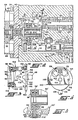
- Fig. 1 is a schematic illustration of a redundant multiple channel electro-mechanical servo system according to the invention;
- Fig. 2 is an enlargeed portion of Fig. 1 showing in section the rotary to linear valve drive mechanism of the servo system;
- Fig. 3 is a top plane view of the drive mechanism of Fig. 2 as viewed from the line 3-3 thereof with parts of the drive mechanism shown partially in section;
- Fig. 4 is a section through the drive mechanism of Fig. 2 taken substantially along the line 4-4 thereof; and
- Fig. 5 is a secton through another embodiment of drive mechanism according to the invention.
- The
servo actuators inlet port 20 for connection with a source of high pressure hydraulic fluid and areturn port 22 for connection with a hydraulic reservoir. Preferably, the respective inlet and return ports of the servo actuators are connected to separate and independent hydraulic systems in the aircraft. In the event one of the hydraulic systemsfails or is shut down, the servo actuator coupled to the other still functioning hydraulic system may be operated to effect the position control function. - In each of the
servo actuators passage 24 connects theinlet port 20 to acheck valve 26. Thecheck valve 26 in turn is connected by apassage 28 to' aservo valve 30. Anotherpassage 32 connects thereturn port 22 to theservo valve 30. - The
servo valve 30 includes aspool 34 which is longitudinally shiftable in asleeve 36. Thesleeve 36 in turn is longitudinally shiftable in atubular insert 38 in thesystem housing 40. The spool and sleeve are divided into two fluidically isolated vaiving sections indicated generally at 42 and 44 in Fig. 1, which valving sections are associated respectively with theactuators passages passages passages 46 and 48 in the same servo actuator. - The
passages 46 and 48 of bothservo actuators cylinder tandem actuator 16 which includes a pair ofcylinders 50. Thepassages 46 and 48 of each servo actuator are connected to a corresponding one of the cylinders at opposite sides of thepiston 52 therein. If desired, anti-cavitation valves may be provided as indicated in thepassages 46 and 48. Thepistons 52 of thecylinders 50 are interconnected by connectingrod 54 and further are connected byoutput rod 56 to thecontrol element 18 throughlinkage 57. - Accordingly, selective relative movement of the
spool 34 andsleeve 36 simultaneously controls both valving sections 42 and 44 which selectively connect one side of eachcylinder 50 to a high pressure hydraulic fluid source and the other side to fluid return for effecting controlled movement of theoutput rod 56 either to the right or left as seen in Fig. 1. In the event one of the servo actuators fails or is shut down, the other servo actuator will maintain control responsive to selective relative movement of the spool and sleeve. - The relatively
shiftable spool 34 andsleeve 36 provide for two separate operational modes for effecting the position control function. The spool, for example, may be operatively associated with a manual operational mode while the sleeve is operatively associated with a control augmented or electrical operational mode. In the manual operational mode, spool postioning may be effected through direct mechanical linkage to a control element in the aircraft cockpit. As seen in Fig. 1, the spool may have acylindrical socket 58 which receives aball 60 at the end of acrank 62. The crank 62 may be connected by a suitable mechanical linkage system to the aircraft cockpit control element. For a detiled description of such a mechanical linkage system, reference may be had to U.S. Patent No. 3,956,971 entitled "Stabilized Hydromechanical Servo System", issued May 18, 1976. - Normally, the manual control mode will remain passive unless a failure renders the electrical mode inoperable. During operation in the electrical mode, the
spool 34 is held in a neutral or centered position while thesleeve 36 is con- trollably shifted to effect the positon control function. - Controlled shifting of the
valve sleeve 36 is effected by avalve drive assembly 63 including arotary force motor 64 which is responsive to electrical command signals received from the aircraft cockpit. Theforce motor 64 preferably has redundant multiple parallel coils so that if one coil or its associated electronics should fail, its counterpart channel will maintain control. Preferably, suitable failure monitoring circuitry is provided to detect when and which channel has failed, and to uncouple or render passive the failed channel. - Referring now additionally to Fig. 2, the
force motor 64 can be seen to include amotor housing 66 which is secured to thesystem housing 40 that contains theservo valve 30. Themotor stator 68 is fixed in the motor housing whereas therotor 70 is journaled bybearings bearings - The
rotor 70 has a central axial bore in which themotor shaft 76 is fixed. Themotor shaft 76 extends through thebase plate 78 of the motor housing into achamber 80 in thesystem housing 40.Suitable seals 82 are provided in thebase plate 78 to preclude passage of hydraulic fluid from thechamber 80 into the interior of themotor 64. - The
shaft 76 of theforce motor 64 is coupled to theservo valve sleeve 36 by adrive mechanism 84 which is contained within thechamber 80 in thesystem housing 40. As best seen in Figs. 2 and 3, thedrive mechanism 84 includes a pair ofrotary input members tubular shaft extension 89 connected to themotor shaft 76 for rotation therewith about the shaft's rotational axis. Therotary members spacer 90 and have opposed parallel axial end faces 92 and 94, respectively, which are commonly inclined or canted at an angle (other than 90°) to the rotational axis of the motor shaft as seen in Fig. 3. Journaled between the axial faces 92 and 94 is a disc or plate-like wobble member 96 which has parallel axial end faces 98 and 100 respectively in bearing engagement with thefaces bearings 102 disposed between the opposed faces of the wobble plate and rotary members. The balls of the bearings are rceived and retained in circular grooves in the faces of the wobble plate and rotary members. In this manner, the wobble member and the bearings are supported between and by the rotary members. - The
drive mechanism 84 is maintained in the above described assembled relationship bydowel pins 104 which are press fitted in bores extending through therotary member spacer 90. When so assembled, the rotary members are maintained in tight engagement with thespacer 90. It should be noted that by carefully selecting the thickness of the spacer i.e., the axial length of the spacer, such as by lapping its axial end faces, the bearing clearance or preload may be precisely set at a predetermined amount at assembly. Preferably, the spacer is lapped to precisely the correct axial length to achieve a slightly preloaded condition without backlash. - The
wobble member 96 can be seen in Fig. 2 to have a radially extendingoutput arm 106. At the radially outermost end of thearm 106, aball 108 is integrally formed or secured thereto. This ball is closely fitted in acylindrical socket 110 provided in anaxial extension 112 on theservo valve sleeve 36. Because the servo valve sleeve is restrained for liner movement along its longitudinal axis in thehousing insert 38, which axis is parallel to the rotational axis of therotary members wobble member 96 is restrained against rotation along with therotary member force motor shaft 76 in response to a command input to theforce motor 64. Accordingly, the wobble member andarm 106 will nutate about an axis perpendicular to the longitudinal axis of the sleeve and also the rotational axis of the rotary members. During such movement of the arm, theball 108 at the end thereof will bear against the sides of thesocket 110 to generate a force along the longitudinal axis of the sleeve for effecting linear movement of such sleeve. The rise and fall of the ball during such arcuate movement will be accommodated by the socket, such ball sliding along the socket in a direction normal to the longitudinal axis of the sleeve. Preferably, there is minimal frictional resistance to such rise and fall motion of the ball to avoid valve sleeve side loads. - To further reduce valve sleeve side loads, the
output arm 106 may be provided with aguide ball 112 which is constrained by laterally spaced parallel guide lands 114 and 115 as illustrated in Fig. 5 wherein primed reference numerals designate elements corresponding generally to those indentified above by the same unprimed reference numerals. The guide lands 114 and 115, which may be fitted in thehousing 40, extend in a direction parallel to the longitudinal axis of thevalve sleeve 36, and accordingly constrain movement of theball 112, and hence theoutput arm 106, against movement in any direction other than in a plain parallel to such axis. In addition, the guide lands 114 and 115 bear any developed lateral side loads and not the valve sleeve. - A linear realtionship essentially exists between the rotary input motion of the
drive motor shaft 76 and the linear motion of thevalve sleeve 36 generally within plus or minus 40° of rotation of the motor shaft from a center or neutral position. It also should be noted that by changing the angle of inclination of thewobble member 96 with respect to the axis of the motor shaft and/or the effective radial length of theoutput arm 106, a wide range of valve stroke/force relationships may be achieved without redesign of the basic drive mechanism configuration and hence with a minimum of hardware changes. - In the event of failure in the electrical mode, an auxiliary input to the
drive mechanism 84 such as the valve centering and lock assembly designated generally byreference numeral 116 in Fig. 1 is provided for controlling failure transients and for positioning theservo valve sleeve 36 at its centered or neutral position. The centering andlock assembly 116 includes acam plunger 118 which is biased by aplunger spring 119 to the left in Fig. 1. Thecam plunger 118 includespistons 120 and 122 which are positioned incylinders cylinders housing 40 and are associated respectively with theservo actuators - The left side of each
cylinder passage 134 to a solenoid-operated shut-offvalve 136. In the energized position of the shut-offvalve 136, fluid communication is established between thepassage 134 and apassage 138 that connects the shut-off valve to thepassage 28. When de-energized upon failure in the electrical operational mode, the shut-off valve connects thepassage 134 to thereturn passage 32. - Accordingly, energization of.each shut-off
valve 136 supplies high pressure fluid to the left side of therespective cylinders respective pistons 120, 122 to the right which in turn forces thecam plunger 118 to the right against theplunger spring 119. Apassage 142 is connected to the right side of eachcylinder return passage 32 to permit such movement of the pistons to the right. - It should be noted that the end of each
passage 134 is bifurcated into twopassages passage 144 is connected to the far left side of therespective cylinders metering orifice 148 for a purpose which will become more apparent below. Theother passage 146 is connected more centrally to the respective cylinder and is open to the left side of the respective pistons 120,122 only when thecam plunger 118 is in or near its retracted position. - As best seen in Figs. 2 and 3, the
cam plunger 118 at its left end has a rounded V-shapednose 150 and a stop shoulder orcollar 152 axially to the right of the nose. When the cam plunger is in its retracted position, thestop collar 152 engages and restrains abrake shoe 154 mounted for sliding movement on the cam plunger. Thebrake shoe 154 is biased to the left by abrake spring 156 positioned between the brake shoe and thecylinder insert 124. Thenose 150 andbrake shoe 154 are adapted to engage respectively acam slot 158 in theouter rotary member 88 andbrake member 160 of thedrive mechanism 84. - Referring now additionally to Fig. 4, the
brake member 160 has an axially extendingcylindrical portion 162 fitted into the interior of thetubular shaft extension 89. The brake member further has a radially extendingbrake plate 164 which is substantially radially offset from the rotational axis of theshaft extension 89. Theplate 164 abuts the end of the tubular end portion of theouter rotary member 88 and is secured thereto for common rotation by pins 166. Such plate has an axiallyouter brake surface 168 adapted for frictional engagement with thebrake shoe 154, and an opening orwindow 170 aligned with thecam slot 158 formed in theouter rotary member 88. - The
cam slot 158 is radially offset from the rotational axis of therotary member 88 and opens axially in longitudinal alignment with thecam plunger 118. The cam slot has slopingside walls 172 which give the slot a V shape. At the vertex of the slot, the side walls slope sharply and substantially axially to form a sharply shouldereddetent 174 having a shape generally corresponding to the shape of thenose 150 of the cam plunger. It should be noted that the detent is circumferentially positioned in the rotary member such that when the plunger nose is received and seated in the detent, theservo valve sleeve 36 will be in its centered or neutral positon and locked therein by reason of the sharp or axial shoulders of the detent that preclude the plunger nose from being cammed out of the detent. - During normal operation of the system in the electrical mode, each shut-off
valve 136 is energized. This supplies hydraulic pressure to the left side of eachpiston 120, 122 thereby retracting thecam plunger 118 to the rightto its retacted position seen in Fig. 1. As the cam plunger nears its retracted position, thestop collar 152 engages thebrake shoe 154 and retracts it out of contact with thebrake plate 164. Accordingly, the valve centering andlock assembly 116 is disengaged to allow controlled positioningorshifting ofthevalve sleeve 36 by thevalve drive mechanism 84 in response to electrical command signals received from the aircraft cockpit. - In the event of failure in both channels of the electrical mode, both shut-off
valves 136 are de-energized. This connects the left side of the pistons to return pressure. Initially, high pressure fluid will fow out of the left side of eachcylinder nonrestricted passage 146 to thereturn port 22 for initial rapid movement of thecam plunger 118 to the left in Fig. 1, such movement being effected byplunger spring 119. This initial rapid movement causes immediate release of the brake shoe 154which is urged by thebrake spring 156 into friction engagement with thebrake plate 164. The brake holding friction will maintain the drive mechanism, and hence the servo valve, in its then existing position. - After such initial rapid movement of the
cam plunger 118, flow through eachpassage 146 will be precluded by itsrespective piston 120, 122 whereupon flow from therespective chamber respective pasage 144 which contains themetering orifice 148. The cam plunger will then move to the left at a predetermined controlled rate as established by the metering orifice and theplunger spring 119. As the cam plunger moves to the left, it will move into thecam slot 170 and into engagement with aside wall 172 thereof to effect centering of the drive mechanism and thus the servo valve. During re- centering, the brake holding friction is overcome. When the cam plunger is fully engaged in thedetent 174 in the cam slot, the drive mechanism is locked in its neutral position. With thevalve sleeve 36 thusly centered and locked, manual operation may be effected through the manual input which selectively controls positioning of thespool 34 with respect to the centered sleeve for effecting the position control function. - From the foregoing, it can now been seen that the
drive mechanism 84 of the present invention is of relatively simple construction while providing many advantages. For instance, the drive mechanism exhibits very good linearity between the rotary motion of theforce motor 64 and the sliding motion at theservo valve sleeve 36 over a desired working range of the valve. In addition, the drive mechanism provides gearing between the force motor output and valve input which easily accommodates gearing changes by relatively simple hardware changes such that a wide range of valve stroke/force relationships may be achieved without re-design of the basic motor/valve configurations. For instance, by changing the angle of the canted faces of therotary members output arm 106, a wide range of gearing may be readily obtained. - The drive mechanism with its inherent gearing provides convenient means for accommodating other control inputs, such as the described braking and recentering device, while taking advantage of the gearing force ratio. This reduces the complexity and size of such other control inputs. That is, the braking and centering functions may be accomplished at the input end of the gearing thereby achieving considerable mechanical advantage to accomplish the braking -and centering functions smoothly. Moreover, when locked, the holding or reactive capability of the mechanism utilizes the input end of the gearing to establish a high mechanical "disadvantage" against any external forces that would tend to backdrive the mechanism during operation in the manual mode.
- The drive mechanism also is freed from inherent backlash and may be pre-loaded at assembly without the need for specially selected ad designed components. Precise control over valve position may be achieved as well as high mechanical stiffness.
Claims (10)
Applications Claiming Priority (2)
| Application Number | Priority Date | Filing Date | Title |
|---|---|---|---|
| US326536 | 1981-12-02 | ||
| US06/326,536 US4466597A (en) | 1981-12-02 | 1981-12-02 | Electro-mechanical direct drive valve servo system with rotary to linear valve drive mechanism |
Publications (3)
| Publication Number | Publication Date |
|---|---|
| EP0080888A2 EP0080888A2 (en) | 1983-06-08 |
| EP0080888A3 EP0080888A3 (en) | 1984-08-22 |
| EP0080888B1 true EP0080888B1 (en) | 1987-03-25 |
Family
ID=23272638
Family Applications (1)
| Application Number | Title | Priority Date | Filing Date |
|---|---|---|---|
| EP82306344A Expired EP0080888B1 (en) | 1981-12-02 | 1982-11-29 | Electro-mechanical direct drive valve servo system with rotary to linear valve drive mechanism |
Country Status (6)
| Country | Link |
|---|---|
| US (1) | US4466597A (en) |
| EP (1) | EP0080888B1 (en) |
| JP (1) | JPS58128509A (en) |
| CA (1) | CA1182382A (en) |
| DE (1) | DE3275852D1 (en) |
| IL (1) | IL67345A (en) |
Families Citing this family (9)
| Publication number | Priority date | Publication date | Assignee | Title |
|---|---|---|---|---|
| EP0164469A1 (en) * | 1984-05-07 | 1985-12-18 | Pneumo Corporation | Direct drive valve and force motor assembly |
| FR2716514B1 (en) | 1994-02-24 | 1996-04-05 | Peugeot | Mechanical control energy transmission device. |
| FI123634B (en) * | 2007-10-05 | 2013-08-30 | Sandvik Mining & Constr Oy | Mining equipment, protective valve and method for using mining equipment |
| US8678033B2 (en) * | 2010-03-24 | 2014-03-25 | Eaton Corporation | Proportional valve employing simultaneous and hybrid actuation |
| JP5981567B2 (en) | 2012-02-09 | 2016-08-31 | ムーグ インコーポレーテッド | Electro-hydraulic servo valve |
| BR112014020497B1 (en) | 2012-02-23 | 2021-03-09 | Moog Inc | direct drive servo valve |
| FR3144971B1 (en) * | 2023-01-18 | 2026-01-30 | Dassault Aviat | Servo control designed to control the position of a moving part of an aircraft |
| FR3144970B1 (en) * | 2023-01-18 | 2025-10-24 | Dassault Aviat | Servo control system for controlling the position of a moving part of an aircraft, made of two distinct materials. |
| US20240384812A1 (en) * | 2023-05-18 | 2024-11-21 | Vrg Controls Llc | Interchangeable Linear Power Module |
Family Cites Families (16)
| Publication number | Priority date | Publication date | Assignee | Title |
|---|---|---|---|---|
| US2294281A (en) * | 1941-09-18 | 1942-08-25 | Glenn A Chadbourne | Mowing machine |
| US2491624A (en) * | 1945-03-29 | 1949-12-20 | Keller Tool Co | Tool operating mechanism |
| GB670352A (en) * | 1949-05-09 | 1952-04-16 | Boulton Aircraft Ltd | Improvements in and relating to duplicated fluid operated power systems |
| GB677672A (en) * | 1949-06-08 | 1952-08-20 | Gen Motors Corp | Improved reciprocable fluid-control valve |
| US2995014A (en) * | 1960-04-26 | 1961-08-08 | Bell Aerospace Corp | Dual electro-hydraulic servo actuator system |
| US3223042A (en) * | 1963-06-14 | 1965-12-14 | Frank Wheatley Corp | Multi-piston variable stroke pump |
| US3580139A (en) * | 1969-04-03 | 1971-05-25 | Honeywell Inc | Control apparatus |
| US3636779A (en) * | 1969-12-05 | 1972-01-25 | Richard J Lappin | Valve drive mechanism |
| US3679156A (en) * | 1970-07-20 | 1972-07-25 | Ltv Electrosystems Inc | Fly-by-wire |
| US3977300A (en) * | 1975-03-18 | 1976-08-31 | United Technologies Corporation | Actuator with feedback |
| US4103556A (en) * | 1976-05-12 | 1978-08-01 | Louis L. Niday | Mechanical movement mechanism |
| GB1578537A (en) * | 1976-07-10 | 1980-11-05 | Lucas Industries Ltd | Control system for a fluid pressure operated actuator arrangement |
| GB1590581A (en) * | 1976-10-14 | 1981-06-03 | Hawker Siddeley Dynamics Eng | Electro-hydraulic systems |
| US4204457A (en) * | 1976-12-30 | 1980-05-27 | Parker-Hannifin Corporation | Device for controlling hydraulic motors |
| US4133511A (en) * | 1977-01-26 | 1979-01-09 | Frieseke & Hoepfner Gmbh | Electro-hydraulic regulating valve system |
| US4176687A (en) * | 1977-08-25 | 1979-12-04 | Cla-Val Co. | Hollow spool valve |
-
1981
- 1981-12-02 US US06/326,536 patent/US4466597A/en not_active Expired - Fee Related
-
1982
- 1982-11-26 IL IL67345A patent/IL67345A/en unknown
- 1982-11-29 DE DE8282306344T patent/DE3275852D1/en not_active Expired
- 1982-11-29 EP EP82306344A patent/EP0080888B1/en not_active Expired
- 1982-11-30 CA CA000416699A patent/CA1182382A/en not_active Expired
- 1982-12-01 JP JP57211200A patent/JPS58128509A/en active Pending
Also Published As
| Publication number | Publication date |
|---|---|
| JPS58128509A (en) | 1983-08-01 |
| EP0080888A2 (en) | 1983-06-08 |
| CA1182382A (en) | 1985-02-12 |
| DE3275852D1 (en) | 1987-04-30 |
| EP0080888A3 (en) | 1984-08-22 |
| US4466597A (en) | 1984-08-21 |
| IL67345A0 (en) | 1983-03-31 |
| IL67345A (en) | 1987-01-30 |
Similar Documents
| Publication | Publication Date | Title |
|---|---|---|
| US6981439B2 (en) | Redundant flow control for hydraulic actuator systems | |
| EP0579117B1 (en) | Variable displacement hydrostatic device and neutral return mechanism therefor | |
| US4672992A (en) | Direct drive valve-ball drive mechanism | |
| US10611464B2 (en) | Electro hydrostatic actuators | |
| US5575150A (en) | Stiffness enhanced electrohydrostatic actuator | |
| US4466597A (en) | Electro-mechanical direct drive valve servo system with rotary to linear valve drive mechanism | |
| US4472998A (en) | Redundant control actuation system-concentric direct drive valve | |
| US6923212B2 (en) | Fail safe apparatus for a direct-drive servovalve | |
| JP7189676B2 (en) | Poppet type flow control valve | |
| US3550631A (en) | Valve plunger drive mechanism | |
| US3722371A (en) | High ratio linkage mechanism | |
| US4548089A (en) | Electro-mechanical direct drive valve servo system with rotary to linear valve drive mechanism | |
| EP1153225B1 (en) | Motor with symmetric braking system | |
| US11549526B2 (en) | Linear and rotary actuators | |
| US4645178A (en) | Redundant drive mechanisms for a direct drive valve and force motor assembly | |
| US12498151B2 (en) | Proportional valve assembly for refrigerant | |
| US7351179B2 (en) | Stepper motor driven proportional actuator | |
| US4534273A (en) | Control actuation system including staged direct drive valve with fault control | |
| US4987927A (en) | Direct-drive valve | |
| EP0115925A1 (en) | Control actuation system including staged direct drive valve with fault control | |
| RU2230944C2 (en) | Redundant electrohydraulic servo drive | |
| US3592236A (en) | Dual-input servo valve | |
| EP4528113A1 (en) | Direct drive valve | |
| RU2237826C2 (en) | Backed-up electrohydraulic drive | |
| EP0164469A1 (en) | Direct drive valve and force motor assembly |
Legal Events
| Date | Code | Title | Description |
|---|---|---|---|
| PUAI | Public reference made under article 153(3) epc to a published international application that has entered the european phase |
Free format text: ORIGINAL CODE: 0009012 |
|
| AK | Designated contracting states |
Designated state(s): BE DE FR GB IT SE |
|
| PUAL | Search report despatched |
Free format text: ORIGINAL CODE: 0009013 |
|
| AK | Designated contracting states |
Designated state(s): BE DE FR GB IT SE |
|
| 17P | Request for examination filed |
Effective date: 19850206 |
|
| 17Q | First examination report despatched |
Effective date: 19860204 |
|
| RAP1 | Party data changed (applicant data changed or rights of an application transferred) |
Owner name: PNEUMO ABEX CORPORATION |
|
| GRAA | (expected) grant |
Free format text: ORIGINAL CODE: 0009210 |
|
| AK | Designated contracting states |
Kind code of ref document: B1 Designated state(s): BE DE FR GB IT SE |
|
| PG25 | Lapsed in a contracting state [announced via postgrant information from national office to epo] |
Ref country code: SE Effective date: 19870325 Ref country code: IT Free format text: LAPSE BECAUSE OF FAILURE TO SUBMIT A TRANSLATION OF THE DESCRIPTION OR TO PAY THE FEE WITHIN THE PRESCRIBED TIME-LIMIT;WARNING: LAPSES OF ITALIAN PATENTS WITH EFFECTIVE DATE BEFORE 2007 MAY HAVE OCCURRED AT ANY TIME BEFORE 2007. THE CORRECT EFFECTIVE DATE MAY BE DIFFERENT FROM THE ONE RECORDED. Effective date: 19870325 Ref country code: FR Free format text: THE PATENT HAS BEEN ANNULLED BY A DECISION OF A NATIONAL AUTHORITY Effective date: 19870325 Ref country code: BE Effective date: 19870325 |
|
| REF | Corresponds to: |
Ref document number: 3275852 Country of ref document: DE Date of ref document: 19870430 |
|
| EN | Fr: translation not filed | ||
| PLBE | No opposition filed within time limit |
Free format text: ORIGINAL CODE: 0009261 |
|
| STAA | Information on the status of an ep patent application or granted ep patent |
Free format text: STATUS: NO OPPOSITION FILED WITHIN TIME LIMIT |
|
| 26N | No opposition filed | ||
| PGFP | Annual fee paid to national office [announced via postgrant information from national office to epo] |
Ref country code: GB Payment date: 19891130 Year of fee payment: 8 Ref country code: DE Payment date: 19891130 Year of fee payment: 8 |
|
| PG25 | Lapsed in a contracting state [announced via postgrant information from national office to epo] |
Ref country code: GB Effective date: 19901129 |
|
| GBPC | Gb: european patent ceased through non-payment of renewal fee | ||
| PG25 | Lapsed in a contracting state [announced via postgrant information from national office to epo] |
Ref country code: DE Effective date: 19910801 |