EP0080707B1 - Construction for holding plastics film - Google Patents
Construction for holding plastics film Download PDFInfo
- Publication number
- EP0080707B1 EP0080707B1 EP82110915A EP82110915A EP0080707B1 EP 0080707 B1 EP0080707 B1 EP 0080707B1 EP 82110915 A EP82110915 A EP 82110915A EP 82110915 A EP82110915 A EP 82110915A EP 0080707 B1 EP0080707 B1 EP 0080707B1
- Authority
- EP
- European Patent Office
- Prior art keywords
- plastics film
- film
- construction
- holding
- plastics
- Prior art date
- Legal status (The legal status is an assumption and is not a legal conclusion. Google has not performed a legal analysis and makes no representation as to the accuracy of the status listed.)
- Expired
Links
Images



Classifications
-
- B—PERFORMING OPERATIONS; TRANSPORTING
- B65—CONVEYING; PACKING; STORING; HANDLING THIN OR FILAMENTARY MATERIAL
- B65D—CONTAINERS FOR STORAGE OR TRANSPORT OF ARTICLES OR MATERIALS, e.g. BAGS, BARRELS, BOTTLES, BOXES, CANS, CARTONS, CRATES, DRUMS, JARS, TANKS, HOPPERS, FORWARDING CONTAINERS; ACCESSORIES, CLOSURES, OR FITTINGS THEREFOR; PACKAGING ELEMENTS; PACKAGES
- B65D83/00—Containers or packages with special means for dispensing contents
- B65D83/08—Containers or packages with special means for dispensing contents for dispensing thin flat articles in succession
- B65D83/0805—Containers or packages with special means for dispensing contents for dispensing thin flat articles in succession through an aperture in a wall
- B65D83/0811—Containers or packages with special means for dispensing contents for dispensing thin flat articles in succession through an aperture in a wall with means for assisting dispensing
-
- B—PERFORMING OPERATIONS; TRANSPORTING
- B65—CONVEYING; PACKING; STORING; HANDLING THIN OR FILAMENTARY MATERIAL
- B65D—CONTAINERS FOR STORAGE OR TRANSPORT OF ARTICLES OR MATERIALS, e.g. BAGS, BARRELS, BOTTLES, BOXES, CANS, CARTONS, CRATES, DRUMS, JARS, TANKS, HOPPERS, FORWARDING CONTAINERS; ACCESSORIES, CLOSURES, OR FITTINGS THEREFOR; PACKAGING ELEMENTS; PACKAGES
- B65D83/00—Containers or packages with special means for dispensing contents
- B65D83/08—Containers or packages with special means for dispensing contents for dispensing thin flat articles in succession
- B65D83/0805—Containers or packages with special means for dispensing contents for dispensing thin flat articles in succession through an aperture in a wall
- B65D83/0811—Containers or packages with special means for dispensing contents for dispensing thin flat articles in succession through an aperture in a wall with means for assisting dispensing
- B65D83/0841—Containers or packages with special means for dispensing contents for dispensing thin flat articles in succession through an aperture in a wall with means for assisting dispensing and for cutting interconnected articles
Definitions
- This invention relates to a construction for holding plastics film comprising a continuous plastics film being partitioned along its longitudinal direction by means of crosswise perforated lines into a multiplicity of sections of predetermined regular links, each of which is of a bag form or a sheet form according to the precharacterizing part of patent claim 1.
- a construction of that kind is disclosed in EP-A-53282, forming part of the state of the art according to Article 54 ( 3 ) E P C.
- the present applicant has proposed a construction for containing the plastics film in Japanese Patent "Kokai" (Lald-Open) No. 96948/82, in which a continuous plastics film is folded such that a linear cut or cuts provided at the respective folded sections are accurately superposed on one another.
- the plastics film is contained in a plastics film container such that insert members projectingly provided in the container are inserted through the linear cuts thus superposed, one end of the first section of film is drawn out to a predetermined length and then the film is cut away along the linear cut or cuts by means of the aforesaid insert members.
- the film is cut away, one end of the succeeding, i.e.
- the insert members to be inserted through the linear cuts of the film are directly affixed to the container, whereby it is difficult to manufacture the container and to automate the process of installing the plastics film, thus presenting the disadvantage that it is difficult to manufacture the container inexpensively.
- EP-A-53282 comprises insert members to be inserted through linear cuts in the plastics film and which are provided on a plate member provided separately from the container.
- the present invention has as its object the provision of a construction for holding the plastics film, wherein, even in comparison with the thus proposed constructions for containing the plastics film, the construction for holding the plastics film can be further inexpensively manufactured and sections of the thus held plastics film can be reliably and easily taken out one section after another.
- the present invention contemplates that said insert member or insert members are provided at the longitudinal sides of the folded plastics film in such a way that they partially encompass said folded plastics film and that one portion of each insert member is inserted in said superposed cuts.
- the present invention provides an arrangement by which the insert member for instance, may be a flexible chord-shaped member of a predetermined length which is once inserted to the linear cut provided on the folded plastics film and the opposite end portions of which are twisted together at a position in the edge region of the stack of plastics films.
- the film is automatically and successively folded by a bearer through a pin in that state where the insert member is inserted into the pin, whereby the process of insertion of the insert member to the linear cut of the plastics film can be eliminated.
- Fig. 1 shows the first embodiment of the construction for holding the plastics film according to the present invention, in which a container 1 is made of paper board or the like and formed into a hollow rectangular parallelepiped, and an elliptical take-out opening 2 is formed in the center of the upper surface of this container 1.
- This take-out opening 2 is formed such that the center of the upper surface of the container 1 is opened by perforated lines provided alorrg-the aforesaid elliptical shape.
- a plastics film folded in a Z-shaped manner Contained in the container 1 is a plastics film folded in a Z-shaped manner.
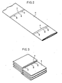
- This plastics film 4 as shown in Fig. 2 for example, is of such an arrangement that a continuous tubular film formed by the tubular film process or the like is folded along lines perpendicular to the longitudinal direction of the plastics film to be formed into double wall portion.
- Linear cuts 5 penetrating through the double wall portion of the film 4 are formed in two lines at regular intervals in a crosswise direction at the intermediate portion of the folded portion of the continuous plastics film in the longitudinal direction of the film.
- Perforated lines 6 are formed along the lines of linear cuts over the entire length in the crosswise direction except at the linear cuts 5.
- the film 4 is connected in the longitudinal direction thereof at three portions in the crosswise direction, including at the central portion, by these portions of perforated lines 6. Furthermore, a heat seal portion 7 is formed by fusion bonding between the double walls adjacent and along the respective linear cuts 5 and perforated lines 6, and this heat seal portion 7 is formed over the entire length of the crosswise direction of the film 4 in parallel with the perforated lines 6, i.e., in a direction perpendicular to the longitudinal direction of the film 4.
- the above-described film 4, as shown in Fig. 3 is (folded in a Z-shaped manner) such that the respective linear cuts 5 are superposed on one another at the center.
- the thus folded, predetermined length, sections of the film 4 are, as shown in Fig. 1, contained in the container 1 in the state of being bent into C-shapes downwardly open in looking from the longitudinal side edges of the film 4.
- Insert members 3 are inserted through the linear cuts 5 thus superposed of the plastics film 4 contained in the container 1, and the film 4 is bundled by the insert members 3 in a folded state.
- the insert members 3 are each formed of a wire-reinforced plastics tape as being a flexible cord-shaped member of a predetermined length, upon being inserted through the linear cuts 5 thus superposed, bent at opposite ends thereof in the -directions of opposite end edges, i.e., to the right and left in Fig. 1, and thereafter, engaged with each other, being twisted together.
- This plate member 10 is made of a material such as paper or plastics, but is not restricted in material quality in particular.
- a take-out opening 12 of an elliptical shape corresponding to the take-out opening 2 of the container 1.
- relief grooves 13 opening at one side of the plate member 10 are formed corresponding to the inserted portions of the insert members 3 of the plastics film 4.
- the plate member 10 is bundled together with the plastics film 4 by means of the insert members 3 inserted through the relief grooves 13 and twisted at the opposite end portions together.
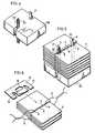
- Fig. 4 shows the essential portions of the stock device used in the manufacture of the present embodiment.
- the top end face of a bearer 20 is formed into a flat plate shape.
- the bearer 20 is vertically displaceable.
- Pins 21 are upwardly projectingly provided at predetermined positions on the top end face of the bearer 20.
- the pins 21 are not vertically displaceable.
- Each of the pins 21 is formed in the longitudinal direction thereof with an elongate groove 22 opening toward the outer periphery of the bearer 20. These elongate grooves 22 are adapted to receive therein the insert members 3.
- the plastics film 4 is folded by a folding machine or the like, not shown, so that the film 4 can be folded by a predetermined width on the bearer 20 with the linear cuts 5 being accurately superposed with one another.
- the pins 21 are inserted through the linear cuts 5, and the bearer 20 gradually descends as the folding progresses.
- the insert members 3 When the plastics film 4 of a predetermined quantity is folded on the bearer 20 as shown in Fig. 5, the insert members 3 are inserted through the elongate grooves 22 (or may be previously inserted therethrough), subsequently, the opposite end portions of the insert members 3 are bent toward the outer periphery of the bearer 20, twisted together and engaged with each other, then the plastics film 4 is bundled by the insert members 3, and thereafter, the plastics film 4 is removed from the bearer 20, thus enabling the completion of the construction for holding the plastics film.
- the plate member 10 is secured to the plastics film 4 in such a manner that the insert members 3 are inserted through the relief grooves 12 as shown in Fig. 6 after the plastics film 4 has been removed from the bearer 20 as described above" the plate member 10 and the plastics film 4 are bundled together by means of the insert members 3. The thus bundled article is installed in the container 1.
- a forward end of the film 4 should be picked out of the take-out opening 2, and then, drawn out.
- an end of the film 4 constituting a second bag subsequent to the first one, engages the insert members 3 because the insert members 3 are inserted through the linear cuts 5, with the result that the opposite end portions and the central portions of the film 4 other than the linear cuts 5, where the perforated lines 6 are formed, are torn off by a resisting force due to the above-described engagement.
- the film 4 When torn off, the film 4 is drawn out of the take-out opening 2 formed in the center of the container 1. Hence, when the film 4 is drawn out by a length of bag, part of the central portion of the succeeding portion of the film 4, connected to the first portion through the perforated lines 6, is drawn out of the take-out opening 2 because the linear cuts 5 of the film 4 have widths to some extent and no resisting force is generated in the draw-out direction until the insert members 3 inserted through the linear cuts 5 reach the opposite end portions of the film 4 where connections are effected through the perforated lines 6.
- the plastics film 4 can be reliably taken out in the same manner as in the pop-up take-out method of tissue paper, one section after another.
- the manufacturing process is very simple, so that the manufacturing efficiency can be improved to a considerable extent.
- the insert members 3 are previously inserted through the film 4 continuously folded on the bearer 20, whereby a predetermined number of sections of the film 4 can be bundled by means of the insert members 3, so that the manufacturing process as a whole can be automated by the provision of a device of cutting the film by a predetermined number of sections and a device of twisting the insert members 3 together, thereby enabling the production at a reduced cost.
- the outer dimensions of the plate member 10 is made slightly smaller than the inner dimensions of the container 1, so that, when the plate member 10 with the plastics film 4 engaged therewith is-inserted into the container 1, the workability is high. Further, the dimensions of the plate member 10 and the container 1 are slightly different in dimensions from each other, whereby there is no possibility of a shift of the take-out opening 12 of the plate member 10 from the take-out opening 2 of the container 1 after the plate member 10 has been installed into the container 1. Moreover, the plate member 10 can be secured to the plastics film 4, which has been bundled by means of the insert members 3, whereby no particular reduction in the manufacturing efficiency is caused due to the provision of the plate member 10.
- this plate member 10 may be replaced by one inserted into the plastics film 4 by every predetermined number of sections of the film 4 folded on the bearer 20, and thereafter, the predetermined number of sections of the plastics film 4 and the plate member 10 are bundled together by means of the insert members 3.
- the plastics film 4 in the above-described embodiment may be replaced by a plastics film 14, a longitudinal side edge of which is opened as shown in Fig. 7 or a plastics film 24 formed of a single sheet as shown in Fig. 8.
- the plastics film 14 shown in Fig. 7 is provided with two linear cuts 15 disposed at regular intervals in the longitudinal direction thereof, perforated lines 16 are provided at a position incorporating the linear cuts 15, and heat seal portions 17 are provided at both sides of the perforated lines 16.
- the plastics film 24 shown in Fig. 8 is provided with two linear cuts 25 disposed at regular intervals in the longitudinal direction thereof, and perforated lines 26 are provided at a position incorporating the linear cuts 25.
- the same operation as those described above can be performed by use of these films 14 and 24.
- the perforated lines 6, 16 or 26 need not necessarily be provided, but, the provision of those perforated lines can offer advantages that facilitate the tear- off operation.
- the number of linear cuts 5, 15 or 25 need not be two, but, may be reduced to one disposed at the center of the film 4,14 or 24 in the widthwise direction or shifted from the center in the widthwise direction toward either one of side edges of the film.
- the plate member 10 has relief grooves 13 opening at one side of the plate member 10, but, this specific form may be replaced by a plate member 110 in the second embodiment shown in Fig. 9, which has cylindrical insertion holes 113.
- the plate member need not necessarily be one which is provided at the side of the take-out opening 2 of the container 1, but, may be one which is provided at a position opposite to the take-out opening 2 of the container 1, i.e. on the side of the bottom of the container 1 like a plate member 210 of the third embodiment shown in Fig. 10.
- the plate member need not necessarily be one which is bundled together with the film by means of the insert members, but, may be one in which the plate members 310 are secured to the film 4 by means of substantially an inverted U-shaped retainers 311 formed separately of the insert members 3 as in the fourth embodiment shown in Fig. 11.
- a stage of work of bundling the film 4 by means of the insert members 3 can be separated from a stage of work of securing the plate members 310 to the film 4, and, the plate members 310 are ones easily secured to the film 4, thus enabling to improve the manufacturing efficiency.
- the plate members 10, 110, 210 and 310 may not be provided at all.
- the insert members 3 are formed of flexible cord-shaped members such as wire-reinforced plastics tapes, however, need not necessarily be plastic or have so-called nerve, but, may be flexible cord-shaped members having no nerve at all such as a simplevinyl cords, cotton strings orthe like.
- the insert members 103 can be easily inserted through the linear cuts 5.
- reference numeral 122 in Fig. 12 designates a spool as being a supply source of the insert members 103.
- the insert members need not necessarily be formed of flexible cord-shaped members, but, may be clips made of plastics, having rigidity and formed into substantially C-shapes like insert members 303 of the fifth embodiment shown in Fig. 13. In the latter case, fingers 303A formed at the side of an opening of the insert member303 should be inserted through the linear cuts 5 of the film 4.
- the installed state of the plastics film 4 folded in the container 1 need not necessarily be the downwardly bent C-shape, but, may be an upwardly bent C-shape or any other shape, or may not be bent at all.
- a container 101 as in the sixth embodiment shown in Fig. 14, is formed of a transparent or opaque polyethylene bag and provided at one side edge thereof with a mount 102.
- the box-shaped or bag-shaped containers need not necessarily be provided. In short, it suffices to retain the folded plastics film.
- the film 4 may be mounted on a plate member 500 functioning as a mount as in the seventh embodiment shown in Fig. 15. in the seventh embodiment shown in Fig. 15, the fiim 4 is secured to and retained on the plate member 500 by means of retainers 501 of substantially U-shape in cross section, which are formed separately of the insert members 3.
- the present invention with the above-described arrangement can provide the holding construction which can be manufactured at a reduced cost, and in which the installed film can be reliably and easily taken out one section after another.
Landscapes
- Engineering & Computer Science (AREA)
- Mechanical Engineering (AREA)
- Packages (AREA)
- Dental Preparations (AREA)
- Containers And Packaging Bodies Having A Special Means To Remove Contents (AREA)
- Sheet Holders (AREA)
Abstract
Description
- This invention relates to a construction for holding plastics film comprising a continuous plastics film being partitioned along its longitudinal direction by means of crosswise perforated lines into a multiplicity of sections of predetermined regular links, each of which is of a bag form or a sheet form according to the precharacterizing part of patent claim 1. A construction of that kind is disclosed in EP-A-53282, forming part of the state of the art according to Article 54(3) EPC.
- Heretofore, there have been proposed various containers in which a multiplicity of bags made of plastics such as polyethylene are to be drawn out therefrom one after another when necessary. Nevertheless, such a bag made of plastics has a frictional resistance by far smaller than a piece of tissue paper, so that drawing out of one bag cannot bring the succeeding bag to a take-out opening by use of the Z-shaped fold-in type pop-up take-out method commonly used in the case of tissue paper, so that the latter method is not practicable for use with plastics bags. In view of the above, there has been proposed a construction, in which continuous plastics bags formed thereon with perforated lines are folded and superposed on one another, these folded bags are received in a container box, and, when a bag is to be drawn out, the aforesaid perforated line is brought into contact with an edge (corner) of the container box to thereby tear the bag off (Japanese Utility Model "Kokai" (Laid Open) No. 52431/79). The above arrangement, however, is disadvantageous in that, when the bag is to be drawn out, the container box must be firmly held, and no such readiness in handling can be offered as with the pop-up take-out method applied to tissue paper.
- Further, there has been proposed such a construction that, plastics bags which have been separated from one another are superposed in a container, with each bag being partially overlapped onto the succeeding one, to thereby generate a force resisting drawing out of the bag in the direction of the draw-out. With the above arrangement, however, the bags could not always be drawn out one after another, but on the contrary, several bags tend to be drawn out together, whereby useless bags are accumulated to a large number, thus proving to be uneconomical.
- To solve the above problems, the present applicant has proposed a construction for containing the plastics film in Japanese Patent "Kokai" (Lald-Open) No. 96948/82, in which a continuous plastics film is folded such that a linear cut or cuts provided at the respective folded sections are accurately superposed on one another. The plastics film is contained in a plastics film container such that insert members projectingly provided in the container are inserted through the linear cuts thus superposed, one end of the first section of film is drawn out to a predetermined length and then the film is cut away along the linear cut or cuts by means of the aforesaid insert members. When the film is cut away, one end of the succeeding, i.e. second, section of the film is automatically drawn out to a take-out opening through the action of connected portions other than the linear cut portions, thereby enabling the achievement of the readiness of the pop-up take-out method as applied to tissue paper and the reliable take-out of the bag-shaped or sheet- shaped film sections one after another.
- However, in the thus proposed construction for containing the plastics film, the insert members to be inserted through the linear cuts of the film are directly affixed to the container, whereby it is difficult to manufacture the container and to automate the process of installing the plastics film, thus presenting the disadvantage that it is difficult to manufacture the container inexpensively.
- The construction disclosed in EP-A-53282 comprises insert members to be inserted through linear cuts in the plastics film and which are provided on a plate member provided separately from the container. Although the work of mounting the insert members onto the plate member is facilitated and the work of fastening of the plastics film and installing the film in the container are automated, thereby providing a manufacture of the container which is less expensive than before, it has been found that further improvements should be made.
- The present invention has as its object the provision of a construction for holding the plastics film, wherein, even in comparison with the thus proposed constructions for containing the plastics film, the construction for holding the plastics film can be further inexpensively manufactured and sections of the thus held plastics film can be reliably and easily taken out one section after another.
- To achieve the above object, the present invention contemplates that said insert member or insert members are provided at the longitudinal sides of the folded plastics film in such a way that they partially encompass said folded plastics film and that one portion of each insert member is inserted in said superposed cuts.
- Thereby, the present invention provides an arrangement by which the insert member for instance, may be a flexible chord-shaped member of a predetermined length which is once inserted to the linear cut provided on the folded plastics film and the opposite end portions of which are twisted together at a position in the edge region of the stack of plastics films. Such an advantage can be offered that the film is automatically and successively folded by a bearer through a pin in that state where the insert member is inserted into the pin, whereby the process of insertion of the insert member to the linear cut of the plastics film can be eliminated.
- The invention may now be further explained with reference to the accompanying drawings in which preferred embodiments of the invention are disclosed.
-
- Fig. 1 is a partially cut-away perspective view showing a first embodiment of the holding construction for holding the plastics film according to the present invention;
- Fig. 2 is a perspective view of the essential portions showing one embodiment of the plastics film used in the embodiment shown in Fig. 1;
- Fig. 3 is a perspective view showing the folded state of the plastics film shown in Fig. 2;
- Fig. 4 is a perspective view of the essential portions showing an embodiment of a stock device used in manufacturing the embodiment shown in Fig. 1;
- Fig. 5 is a perspective view showing the plastics film shown in Fig. 2, folded into the stock device shown in Fig. 4;
- Fig. 6 is a perspective view showing the state where a plate member is secured to the plastics film shown in Fig. 2, folded by the stock device shown in Fig. 4;
- Figs. 7 and 8 are perspective views of the essential portions showing other embodiments of the plastics film differing from each other according to the present invention;
- Figs. 9 through 11 are perspective views, partially cut away, showing a second through a fourth embodiments;
- Fig. 12 is a perspective view showing the state where the plastics film shown in Fig. 2 is folded by an embodiment of the stock device other than the above;'
- Figs. 13 is a perspective view, partially cut away, showing a fifth embodiment; and
- Figs. 14 and 15 are perspective views showing a sixth and a seventh embodiments, respectively.
- Fig. 1 shows the first embodiment of the construction for holding the plastics film according to the present invention, in which a container 1 is made of paper board or the like and formed into a hollow rectangular parallelepiped, and an elliptical take-out
opening 2 is formed in the center of the upper surface of this container 1. This take-out opening 2 is formed such that the center of the upper surface of the container 1 is opened by perforated lines provided alorrg-the aforesaid elliptical shape. - Contained in the container 1 is a plastics film folded in a Z-shaped manner. This
plastics film 4, as shown in Fig. 2 for example, is of such an arrangement that a continuous tubular film formed by the tubular film process or the like is folded along lines perpendicular to the longitudinal direction of the plastics film to be formed into double wall portion.Linear cuts 5 penetrating through the double wall portion of thefilm 4 are formed in two lines at regular intervals in a crosswise direction at the intermediate portion of the folded portion of the continuous plastics film in the longitudinal direction of the film.Perforated lines 6 are formed along the lines of linear cuts over the entire length in the crosswise direction except at thelinear cuts 5. Thefilm 4 is connected in the longitudinal direction thereof at three portions in the crosswise direction, including at the central portion, by these portions ofperforated lines 6. Furthermore, aheat seal portion 7 is formed by fusion bonding between the double walls adjacent and along the respectivelinear cuts 5 andperforated lines 6, and thisheat seal portion 7 is formed over the entire length of the crosswise direction of thefilm 4 in parallel with theperforated lines 6, i.e., in a direction perpendicular to the longitudinal direction of thefilm 4. - The above-described
film 4, as shown in Fig. 3 is (folded in a Z-shaped manner) such that the respectivelinear cuts 5 are superposed on one another at the center. The thus folded, predetermined length, sections of thefilm 4 are, as shown in Fig. 1, contained in the container 1 in the state of being bent into C-shapes downwardly open in looking from the longitudinal side edges of thefilm 4. - Insert
members 3 are inserted through thelinear cuts 5 thus superposed of theplastics film 4 contained in the container 1, and thefilm 4 is bundled by theinsert members 3 in a folded state. - The
insert members 3 are each formed of a wire-reinforced plastics tape as being a flexible cord-shaped member of a predetermined length, upon being inserted through thelinear cuts 5 thus superposed, bent at opposite ends thereof in the -directions of opposite end edges, i.e., to the right and left in Fig. 1, and thereafter, engaged with each other, being twisted together. - A
plate member 10 slightly smaller than the inside dimensions of the container 1 and capable of being readily put into and taken out of the container 1 is disposed inside a surface of the container 1 where the take-out opening is formed. Thisplate member 10 is made of a material such as paper or plastics, but is not restricted in material quality in particular. - Formed at the central portion of the
plate member 10 is a take-out opening 12 of an elliptical shape corresponding to the take-outopening 2 of the container 1. At longitudinally opposite ends of this take-out opening 12 as seen in Fig. 1,relief grooves 13 opening at one side of theplate member 10 are formed corresponding to the inserted portions of theinsert members 3 of theplastics film 4. Theplate member 10 is bundled together with theplastics film 4 by means of theinsert members 3 inserted through therelief grooves 13 and twisted at the opposite end portions together. - Description will hereunder be given of the manufacturing process of the present embodiment.
- Fig. 4 shows the essential portions of the stock device used in the manufacture of the present embodiment. In this drawing, the top end face of a
bearer 20 is formed into a flat plate shape. Thebearer 20 is vertically displaceable.Pins 21 are upwardly projectingly provided at predetermined positions on the top end face of thebearer 20. Thepins 21 are not vertically displaceable. - Each of the
pins 21 is formed in the longitudinal direction thereof with anelongate groove 22 opening toward the outer periphery of thebearer 20. Theseelongate grooves 22 are adapted to receive therein theinsert members 3. - The
plastics film 4 is folded by a folding machine or the like, not shown, so that thefilm 4 can be folded by a predetermined width on thebearer 20 with thelinear cuts 5 being accurately superposed with one another. In this case, thepins 21 are inserted through thelinear cuts 5, and thebearer 20 gradually descends as the folding progresses. - When the
plastics film 4 of a predetermined quantity is folded on thebearer 20 as shown in Fig. 5, theinsert members 3 are inserted through the elongate grooves 22 (or may be previously inserted therethrough), subsequently, the opposite end portions of theinsert members 3 are bent toward the outer periphery of thebearer 20, twisted together and engaged with each other, then theplastics film 4 is bundled by theinsert members 3, and thereafter, theplastics film 4 is removed from thebearer 20, thus enabling the completion of the construction for holding the plastics film. - If the
plate member 10 is secured to theplastics film 4 in such a manner that theinsert members 3 are inserted through therelief grooves 12 as shown in Fig. 6 after theplastics film 4 has been removed from thebearer 20 as described above" theplate member 10 and theplastics film 4 are bundled together by means of theinsert members 3. The thus bundled article is installed in the container 1. - To take out a section of a predetermined length of the
plastics film 4 to form a bag in the present embodiment, firstly, a forward end of thefilm 4 should be picked out of the take-outopening 2, and then, drawn out. When thefilm 4 folded and contained in the container 1 is drawn out by a length of bag, an end of thefilm 4, constituting a second bag subsequent to the first one, engages theinsert members 3 because theinsert members 3 are inserted through thelinear cuts 5, with the result that the opposite end portions and the central portions of thefilm 4 other than thelinear cuts 5, where theperforated lines 6 are formed, are torn off by a resisting force due to the above-described engagement. When torn off, thefilm 4 is drawn out of the take-outopening 2 formed in the center of the container 1. Hence, when thefilm 4 is drawn out by a length of bag, part of the central portion of the succeeding portion of thefilm 4, connected to the first portion through theperforated lines 6, is drawn out of the take-outopening 2 because thelinear cuts 5 of thefilm 4 have widths to some extent and no resisting force is generated in the draw-out direction until theinsert members 3 inserted through thelinear cuts 5 reach the opposite end portions of thefilm 4 where connections are effected through theperforated lines 6. If the draw-out operation is continued in this condition, the opposite end portions of thefilm 4 connected to the succeeding section of thefilm 4 through theperforated lines 6 engage theinsert members 3 as if the opposite end portions of thefilm 4 are wound around theinsert member 3. At this time, tensile forces act on the opposite end portions of thefilm 4, whereby, firstly, theperforated lines 6 at the opposite end portions are cut. Thereafter, if the draw-out operation is further continued, a tensile force acts on the central portion of thefilm 4 due to a resisting force resulting from the engagement of the opposite end portions of thefilm 4 with theinsert members 3, whereby theperforated line 6 at the central portion is cut. In consequence, part of the succeeding section of thefilm 4 should project out of the take-outopening 2 without fail. - With this embodiment as described above, the
plastics film 4 can be reliably taken out in the same manner as in the pop-up take-out method of tissue paper, one section after another. - Moreover, the manufacturing process is very simple, so that the manufacturing efficiency can be improved to a considerable extent. Further, the
insert members 3 are previously inserted through thefilm 4 continuously folded on thebearer 20, whereby a predetermined number of sections of thefilm 4 can be bundled by means of theinsert members 3, so that the manufacturing process as a whole can be automated by the provision of a device of cutting the film by a predetermined number of sections and a device of twisting theinsert members 3 together, thereby enabling the production at a reduced cost. - Furthermore, the outer dimensions of the
plate member 10 is made slightly smaller than the inner dimensions of the container 1, so that, when theplate member 10 with theplastics film 4 engaged therewith is-inserted into the container 1, the workability is high. Further, the dimensions of theplate member 10 and the container 1 are slightly different in dimensions from each other, whereby there is no possibility of a shift of the take-outopening 12 of theplate member 10 from the take-outopening 2 of the container 1 after theplate member 10 has been installed into the container 1. Moreover, theplate member 10 can be secured to theplastics film 4, which has been bundled by means of theinsert members 3, whereby no particular reduction in the manufacturing efficiency is caused due to the provision of theplate member 10. Further, thisplate member 10 may be replaced by one inserted into theplastics film 4 by every predetermined number of sections of thefilm 4 folded on thebearer 20, and thereafter, the predetermined number of sections of theplastics film 4 and theplate member 10 are bundled together by means of theinsert members 3. - In working the invention, the
plastics film 4 in the above-described embodiment may be replaced by aplastics film 14, a longitudinal side edge of which is opened as shown in Fig. 7 or aplastics film 24 formed of a single sheet as shown in Fig. 8. Theplastics film 14 shown in Fig. 7 is provided with twolinear cuts 15 disposed at regular intervals in the longitudinal direction thereof,perforated lines 16 are provided at a position incorporating thelinear cuts 15, andheat seal portions 17 are provided at both sides of theperforated lines 16. Further, theplastics film 24 shown in Fig. 8 is provided with twolinear cuts 25 disposed at regular intervals in the longitudinal direction thereof, andperforated lines 26 are provided at a position incorporating thelinear cuts 25. The same operation as those described above can be performed by use of thesefilms perforated lines linear cuts film linear cuts film linear cut linear cut film film linear cuts film film linear cuts film insert members 3 are inserted at opposite sides of the take-out opening, then there are presented advantages such that a resisting force present when thefilm film - In the above-described embodiment, the
plate member 10 hasrelief grooves 13 opening at one side of theplate member 10, but, this specific form may be replaced by aplate member 110 in the second embodiment shown in Fig. 9, which has cylindrical insertion holes 113. - Furthermore, the plate member need not necessarily be one which is provided at the side of the take-out
opening 2 of the container 1, but, may be one which is provided at a position opposite to the take-outopening 2 of the container 1, i.e. on the side of the bottom of the container 1 like aplate member 210 of the third embodiment shown in Fig. 10. Further, the plate member need not necessarily be one which is bundled together with the film by means of the insert members, but, may be one in which theplate members 310 are secured to thefilm 4 by means of substantially an invertedU-shaped retainers 311 formed separately of theinsert members 3 as in the fourth embodiment shown in Fig. 11. In this case, a stage of work of bundling thefilm 4 by means of theinsert members 3 can be separated from a stage of work of securing theplate members 310 to thefilm 4, and, theplate members 310 are ones easily secured to thefilm 4, thus enabling to improve the manufacturing efficiency. In addition, theplate members - Further, in the above-described embodiment, the
insert members 3 are formed of flexible cord-shaped members such as wire-reinforced plastics tapes, however, need not necessarily be plastic or have so-called nerve, but, may be flexible cord-shaped members having no nerve at all such as a simplevinyl cords, cotton strings orthe like. In this case, as shown in Fig. 12, ifpins 120 are formed into tubular forms and insertmembers 103 formed of cotton strings or the like are inserted throughhollow portions 121 of thepins 120, then insertmembers 103 can be easily inserted through thelinear cuts 5. In addition,reference numeral 122 in Fig. 12 designates a spool as being a supply source of theinsert members 103. - Furthermore, the insert members need not necessarily be formed of flexible cord-shaped members, but, may be clips made of plastics, having rigidity and formed into substantially C-shapes like
insert members 303 of the fifth embodiment shown in Fig. 13. In the latter case,fingers 303A formed at the side of an opening of the insert member303 should be inserted through thelinear cuts 5 of thefilm 4. - Further, the installed state of the
plastics film 4 folded in the container 1 need not necessarily be the downwardly bent C-shape, but, may be an upwardly bent C-shape or any other shape, or may not be bent at all. - Furthermore, the container need not necessarily be the hollow parallelepiped, i.e. box shape, but, may be replaced by a plastics bag made of polyethylene or the like, which is very inexpensive as compared with the box-shaped one. More specifically, a
container 101 as in the sixth embodiment shown in Fig. 14, is formed of a transparent or opaque polyethylene bag and provided at one side edge thereof with amount 102. - Further, the box-shaped or bag-shaped containers need not necessarily be provided. In short, it suffices to retain the folded plastics film. In consequence, the
film 4 may be mounted on aplate member 500 functioning as a mount as in the seventh embodiment shown in Fig. 15. in the seventh embodiment shown in Fig. 15, thefiim 4 is secured to and retained on theplate member 500 by means ofretainers 501 of substantially U-shape in cross section, which are formed separately of theinsert members 3. - The present invention with the above-described arrangement can provide the holding construction which can be manufactured at a reduced cost, and in which the installed film can be reliably and easily taken out one section after another.
Claims (12)
Priority Applications (1)
| Application Number | Priority Date | Filing Date | Title |
|---|---|---|---|
| AT82110915T ATE21372T1 (en) | 1981-12-01 | 1982-11-25 | DEVICE FOR HOLDING A PLASTIC FILM. |
Applications Claiming Priority (2)
| Application Number | Priority Date | Filing Date | Title |
|---|---|---|---|
| JP194004/81 | 1981-12-01 | ||
| JP56194004A JPS5899372A (en) | 1981-12-01 | 1981-12-01 | Encasing structure of plastic film |
Publications (2)
| Publication Number | Publication Date |
|---|---|
| EP0080707A1 EP0080707A1 (en) | 1983-06-08 |
| EP0080707B1 true EP0080707B1 (en) | 1986-08-13 |
Family
ID=16317364
Family Applications (1)
| Application Number | Title | Priority Date | Filing Date |
|---|---|---|---|
| EP82110915A Expired EP0080707B1 (en) | 1981-12-01 | 1982-11-25 | Construction for holding plastics film |
Country Status (6)
| Country | Link |
|---|---|
| US (1) | US4506801A (en) |
| EP (1) | EP0080707B1 (en) |
| JP (1) | JPS5899372A (en) |
| AT (1) | ATE21372T1 (en) |
| CA (1) | CA1235395A (en) |
| DE (1) | DE3272622D1 (en) |
Families Citing this family (23)
| Publication number | Priority date | Publication date | Assignee | Title |
|---|---|---|---|---|
| US4592739A (en) * | 1982-01-20 | 1986-06-03 | Idemitsu Petrochemical Co., Ltd. | Web material folding device |
| US4637812A (en) * | 1984-09-12 | 1987-01-20 | Idemitsu Petrochemical Co., Ltd. | Apparatus for folding web-shaped member |
| US4708243A (en) * | 1986-05-06 | 1987-11-24 | Nailon Wayne M | Portable bag storage assembly |
| US4850508A (en) * | 1988-07-05 | 1989-07-25 | Lee Lawrence K | Litter disposal mechanism |
| US4850486A (en) * | 1988-10-17 | 1989-07-25 | Neibaur Ira L | Trash and like bag and bag closure storage and dispensing |
| US5269423A (en) * | 1992-03-16 | 1993-12-14 | Advance Polybag, Inc. | Bag dispenser system |
| US5348399A (en) * | 1992-12-23 | 1994-09-20 | Dematteis Robert B | Plastic bags with waveform edge configurations |
| EP0618148B1 (en) * | 1993-03-30 | 1997-10-29 | The Procter & Gamble Company | Sleeved stacks for compact packaging of flexible articles |
| US5353950A (en) * | 1993-09-13 | 1994-10-11 | Taylor Richard S | Collapsible trash bag dispenser for dispensing trash bags from the bottom of a trash container |
| US5755355A (en) * | 1995-12-15 | 1998-05-26 | Minnesota Mining And Manufacturing Company | Pad including coadhesively adhered sheets |
| USD398841S (en) | 1996-04-02 | 1998-09-29 | Tim Sargent | Trash bag receptacle |
| US6013722A (en) * | 1998-01-27 | 2000-01-11 | 3M Innovative Properties Company | Non-whitening emulsion pressure sensitive adhesives |
| US6056235A (en) * | 1998-05-28 | 2000-05-02 | Brozinsky; Steven | Refillable dispenser for replacing standard roll of toilet tissue with roll of pre-moistened wipes |
| US6575301B2 (en) * | 2001-07-16 | 2003-06-10 | Ebrahim Simhaee | Plastic bag package |
| US20030111381A1 (en) * | 2001-12-14 | 2003-06-19 | Somsak Borrisuttanakul | Bag dispenser and a bag unit therefore |
| US6967951B2 (en) * | 2002-01-11 | 2005-11-22 | Internet Machines Corp. | System for reordering sequenced based packets in a switching network |
| US7624881B2 (en) * | 2004-01-20 | 2009-12-01 | Hilex Poly Co., Llc | Dispensing apparatus for plastic bags |
| US20050279757A1 (en) * | 2004-06-16 | 2005-12-22 | Bitowft Bruce K | Wipes dispenser with a wide-mouthed dispensing aperture |
| US8083097B2 (en) * | 2004-09-30 | 2011-12-27 | Kimberly-Clark Worldwide, Inc | Interleaved towel fold configuration |
| US20070062967A1 (en) * | 2005-09-13 | 2007-03-22 | Uri Zaidman | System, container, pack and method for packing and dispensing wipes |
| US7926680B2 (en) * | 2007-08-31 | 2011-04-19 | Kimberly-Clark Worldwide, Inc. | Carton with internal clip retainer for dispensing clips of a stacked sheet material |
| US20170305606A1 (en) * | 2016-04-25 | 2017-10-26 | Better Bags, Inc. | Packs of Plastic Bags and Racks for Suspending The Packs of Plastic Bags |
| US12552597B2 (en) * | 2024-05-01 | 2026-02-17 | 2574718 Alberta LTD. | Packaged grain/silage bag |
Family Cites Families (17)
| Publication number | Priority date | Publication date | Assignee | Title |
|---|---|---|---|---|
| US487026A (en) * | 1892-11-29 | Toilet or wrapping paper | ||
| US374399A (en) * | 1887-12-06 | Toilet-paper fixture | ||
| US445857A (en) * | 1891-02-03 | Sample-case | ||
| US2077664A (en) * | 1935-11-08 | 1937-04-20 | Brown Co | Pad of paper sheets for hanging on a wall |
| FR1218534A (en) * | 1958-12-16 | 1960-05-11 | Lincrusta | Packaging for elongated flat objects |
| US3198325A (en) * | 1960-08-12 | 1965-08-03 | Bemis Bro Bag Co | Bag package |
| US3221929A (en) * | 1962-06-22 | 1965-12-07 | Jack E Dominik | Paper towel dispenser |
| US3266666A (en) * | 1965-01-12 | 1966-08-16 | Kimberly Clark Co | Tissue dispensing carton having a detachable control panel as an integral part of the top wall |
| US3338398A (en) * | 1966-07-29 | 1967-08-29 | Eagle Picher Co | Flexible plastic bag package |
| US3380579A (en) * | 1967-06-20 | 1968-04-30 | Young William E | Grouping of flexible bags |
| DE2408831A1 (en) * | 1974-02-23 | 1975-08-28 | Elwaplastic Maschinenbau Gmbh | Paper or plastics bag block - has bags stacked in pairs and held by clips along joining line |
| US3918589A (en) * | 1974-11-04 | 1975-11-11 | Union Carbide Corp | Pivoted wicket bag opening dispenser |
| GB1575072A (en) * | 1977-03-09 | 1980-09-17 | Vila Omella R | An assembly of bags |
| JPS5452431A (en) * | 1977-10-04 | 1979-04-25 | Toshiba Corp | Semiconductor memory device |
| US4305503A (en) * | 1980-04-24 | 1981-12-15 | Hercules Membrino | Package of plastic bags |
| EP0053282B1 (en) * | 1980-11-28 | 1985-01-30 | Idemitsu Kosan Company Limited | Construction for containing plastics film |
| JPS5940702A (en) * | 1982-08-30 | 1984-03-06 | Matsushita Electric Ind Co Ltd | Converter of waveguide-strip line |
-
1981
- 1981-12-01 JP JP56194004A patent/JPS5899372A/en active Pending
-
1982
- 1982-11-22 US US06/443,790 patent/US4506801A/en not_active Expired - Fee Related
- 1982-11-22 CA CA000416070A patent/CA1235395A/en not_active Expired
- 1982-11-25 EP EP82110915A patent/EP0080707B1/en not_active Expired
- 1982-11-25 AT AT82110915T patent/ATE21372T1/en active
- 1982-11-25 DE DE8282110915T patent/DE3272622D1/en not_active Expired
Also Published As
| Publication number | Publication date |
|---|---|
| US4506801A (en) | 1985-03-26 |
| JPS5899372A (en) | 1983-06-13 |
| CA1235395A (en) | 1988-04-19 |
| DE3272622D1 (en) | 1986-09-18 |
| ATE21372T1 (en) | 1986-08-15 |
| EP0080707A1 (en) | 1983-06-08 |
Similar Documents
| Publication | Publication Date | Title |
|---|---|---|
| US4506801A (en) | Construction for holding plastic film | |
| US4453649A (en) | Construction for containing plastic film | |
| SE453283B (en) | PLACE PHASE AND WAY TO MAKE IT SAME | |
| US4484904A (en) | Manufacturing plastic bags | |
| US7036987B2 (en) | Reclosable bag having wicket flap and slider-actuated string zipper | |
| US6131370A (en) | Zipper applied across a film in transverse direction | |
| US4207983A (en) | Packeting net bags | |
| AU6662494A (en) | A web for package blanks | |
| EP0972715A1 (en) | Fastener assembly for plastics bag | |
| US5203634A (en) | Double guide strip opening device | |
| US4720010A (en) | Stock assembly for storing and successively supplying closed loop members for suspending sausages | |
| US7165886B2 (en) | Top-fill reclosable bag having wicket flap and related method of manufacture | |
| CN118343343B (en) | Intelligent chip in-box packaging equipment and packaging technology thereof | |
| US4292033A (en) | Method of providing net bags with wicketing flaps | |
| US4700883A (en) | Tubular package and end cap forming component of same | |
| US5961434A (en) | Method and apparatus for arranging twist-ties | |
| EP0395370B1 (en) | A method of packaging objects | |
| EP0016601B1 (en) | Thermoplastic bags | |
| EP1110876B1 (en) | Slider device and method for positioning a slider device onto reclosable packaging | |
| EP1447341A1 (en) | Bag with suspension means and a slider operated zipper | |
| US7604407B2 (en) | Closure strips for a sheet or a bag, and a resulting sheet or a bag | |
| JPS5940703B2 (en) | plastic film packaging | |
| EP0129269B1 (en) | Device for sealing coin containing bag or the like | |
| GB2235883A (en) | Lateral tear tapes | |
| EP0293527B1 (en) | Tubular package and end cap forming component of same |
Legal Events
| Date | Code | Title | Description |
|---|---|---|---|
| PUAI | Public reference made under article 153(3) epc to a published international application that has entered the european phase |
Free format text: ORIGINAL CODE: 0009012 |
|
| AK | Designated contracting states |
Designated state(s): AT BE CH DE FR GB IT LI LU NL SE |
|
| 17P | Request for examination filed |
Effective date: 19830713 |
|
| GRAA | (expected) grant |
Free format text: ORIGINAL CODE: 0009210 |
|
| AK | Designated contracting states |
Kind code of ref document: B1 Designated state(s): AT BE CH DE FR GB IT LI LU NL SE |
|
| REF | Corresponds to: |
Ref document number: 21372 Country of ref document: AT Date of ref document: 19860815 Kind code of ref document: T |
|
| ITF | It: translation for a ep patent filed | ||
| REF | Corresponds to: |
Ref document number: 3272622 Country of ref document: DE Date of ref document: 19860918 |
|
| ET | Fr: translation filed | ||
| PGFP | Annual fee paid to national office [announced via postgrant information from national office to epo] |
Ref country code: AT Payment date: 19861114 Year of fee payment: 5 |
|
| PG25 | Lapsed in a contracting state [announced via postgrant information from national office to epo] |
Ref country code: LU Free format text: LAPSE BECAUSE OF NON-PAYMENT OF DUE FEES Effective date: 19861130 |
|
| PLBE | No opposition filed within time limit |
Free format text: ORIGINAL CODE: 0009261 |
|
| STAA | Information on the status of an ep patent application or granted ep patent |
Free format text: STATUS: NO OPPOSITION FILED WITHIN TIME LIMIT |
|
| 26N | No opposition filed | ||
| PGFP | Annual fee paid to national office [announced via postgrant information from national office to epo] |
Ref country code: NL Payment date: 19871130 Year of fee payment: 6 |
|
| ITTA | It: last paid annual fee | ||
| PGFP | Annual fee paid to national office [announced via postgrant information from national office to epo] |
Ref country code: DE Payment date: 19881230 Year of fee payment: 7 |
|
| PG25 | Lapsed in a contracting state [announced via postgrant information from national office to epo] |
Ref country code: GB Effective date: 19891125 Ref country code: AT Effective date: 19891125 |
|
| PG25 | Lapsed in a contracting state [announced via postgrant information from national office to epo] |
Ref country code: SE Effective date: 19891126 |
|
| PG25 | Lapsed in a contracting state [announced via postgrant information from national office to epo] |
Ref country code: LI Effective date: 19891130 Ref country code: CH Effective date: 19891130 Ref country code: BE Effective date: 19891130 |
|
| BERE | Be: lapsed |
Owner name: IDEMITSU KOSAN CY LTD Effective date: 19891130 |
|
| PG25 | Lapsed in a contracting state [announced via postgrant information from national office to epo] |
Ref country code: NL Effective date: 19900601 |
|
| NLV4 | Nl: lapsed or anulled due to non-payment of the annual fee | ||
| GBPC | Gb: european patent ceased through non-payment of renewal fee | ||
| PG25 | Lapsed in a contracting state [announced via postgrant information from national office to epo] |
Ref country code: FR Effective date: 19900731 |
|
| REG | Reference to a national code |
Ref country code: CH Ref legal event code: PL |
|
| PG25 | Lapsed in a contracting state [announced via postgrant information from national office to epo] |
Ref country code: DE Effective date: 19900801 |
|
| REG | Reference to a national code |
Ref country code: FR Ref legal event code: ST |
|
| EUG | Se: european patent has lapsed |
Ref document number: 82110915.4 Effective date: 19900705 |