EP0079789B1 - Solar powered engine - Google Patents
Solar powered engine Download PDFInfo
- Publication number
- EP0079789B1 EP0079789B1 EP82306063A EP82306063A EP0079789B1 EP 0079789 B1 EP0079789 B1 EP 0079789B1 EP 82306063 A EP82306063 A EP 82306063A EP 82306063 A EP82306063 A EP 82306063A EP 0079789 B1 EP0079789 B1 EP 0079789B1
- Authority
- EP
- European Patent Office
- Prior art keywords
- piston
- port
- reservoir
- condenser
- liquid
- Prior art date
- Legal status (The legal status is an assumption and is not a legal conclusion. Google has not performed a legal analysis and makes no representation as to the accuracy of the status listed.)
- Expired
Links
Images


Classifications
-
- F—MECHANICAL ENGINEERING; LIGHTING; HEATING; WEAPONS; BLASTING
- F22—STEAM GENERATION
- F22D—PREHEATING, OR ACCUMULATING PREHEATED, FEED-WATER FOR STEAM GENERATION; FEED-WATER SUPPLY FOR STEAM GENERATION; CONTROLLING WATER LEVEL FOR STEAM GENERATION; AUXILIARY DEVICES FOR PROMOTING WATER CIRCULATION WITHIN STEAM BOILERS
- F22D11/00—Feed-water supply not provided for in other main groups
- F22D11/02—Arrangements of feed-water pumps
- F22D11/06—Arrangements of feed-water pumps for returning condensate to boiler
-
- F—MECHANICAL ENGINEERING; LIGHTING; HEATING; WEAPONS; BLASTING
- F03—MACHINES OR ENGINES FOR LIQUIDS; WIND, SPRING, OR WEIGHT MOTORS; PRODUCING MECHANICAL POWER OR A REACTIVE PROPULSIVE THRUST, NOT OTHERWISE PROVIDED FOR
- F03G—SPRING, WEIGHT, INERTIA OR LIKE MOTORS; MECHANICAL-POWER PRODUCING DEVICES OR MECHANISMS, NOT OTHERWISE PROVIDED FOR OR USING ENERGY SOURCES NOT OTHERWISE PROVIDED FOR
- F03G6/00—Devices for producing mechanical power from solar energy
- F03G6/003—Devices for producing mechanical power from solar energy having a Rankine cycle
-
- F—MECHANICAL ENGINEERING; LIGHTING; HEATING; WEAPONS; BLASTING
- F03—MACHINES OR ENGINES FOR LIQUIDS; WIND, SPRING, OR WEIGHT MOTORS; PRODUCING MECHANICAL POWER OR A REACTIVE PROPULSIVE THRUST, NOT OTHERWISE PROVIDED FOR
- F03G—SPRING, WEIGHT, INERTIA OR LIKE MOTORS; MECHANICAL-POWER PRODUCING DEVICES OR MECHANISMS, NOT OTHERWISE PROVIDED FOR OR USING ENERGY SOURCES NOT OTHERWISE PROVIDED FOR
- F03G6/00—Devices for producing mechanical power from solar energy
- F03G6/071—Devices for producing mechanical power from solar energy with energy storage devices
-
- Y—GENERAL TAGGING OF NEW TECHNOLOGICAL DEVELOPMENTS; GENERAL TAGGING OF CROSS-SECTIONAL TECHNOLOGIES SPANNING OVER SEVERAL SECTIONS OF THE IPC; TECHNICAL SUBJECTS COVERED BY FORMER USPC CROSS-REFERENCE ART COLLECTIONS [XRACs] AND DIGESTS
- Y02—TECHNOLOGIES OR APPLICATIONS FOR MITIGATION OR ADAPTATION AGAINST CLIMATE CHANGE
- Y02E—REDUCTION OF GREENHOUSE GAS [GHG] EMISSIONS, RELATED TO ENERGY GENERATION, TRANSMISSION OR DISTRIBUTION
- Y02E10/00—Energy generation through renewable energy sources
- Y02E10/40—Solar thermal energy, e.g. solar towers
- Y02E10/46—Conversion of thermal power into mechanical power, e.g. Rankine, Stirling or solar thermal engines
Definitions
- This invention relates to an engine in which solar power is used as the source of energy to produce a power output from the engine.
- FR-A-2 428 157 discloses a closed circuit solar engine in which a fluid such as Freon is vapourised in a solar collector and fed via a three port two-way valve (of which no detail is given) into a flexible inflatable bag which inflates and thus lifts a plate to perform work.
- the valve moves to close off the flow of vapourised liquid from the solar collector and connect the bag to the condenser.
- the plate descends under the influence of gravity and causes the vapourised liquid in the bag to exhaust to the condenser.
- the vapourised liquid condenses in the condenser and then flows back again under the influence of gravity to the solar collector.
- the engine relies solely on the force of gravity to return the condensed liquid from the condenser to the solar collector.
- a solar powered engine comprising:
- the engine of the present invention utilises not only the force of gravity, but also the difference in fluid levels in the collector and the condenser, and the pressure exerted by the vapourised fluid, to return the condensed liquid from the condenser to the solar collector. Further, the engine of the present invention does not utilise an inflatable flexible bag with a movable plate thereon, but a piston movable in a sealed chamber.
- valve means when the valve means is in its first position, the pressures in the reservoir and in the soloar collector are allowed to equalise and when the valve means is in its second position, the pressures in the reservoir and in the condenser are allowed to equalise.
- the valve means preferably comprises a three-port two-position valve, the first port communicating with the solar collector, the second port communicating with the inlet and the third port communicating with the vapour end of the condenser, and a vapour passage is provided between the chamber below the piston and the reservoir above the liquid level therein, the valve being movable between a first position in which the first port is in communication with the second port so that the pressures in the solar collector, the chamber below the piston and the reservoir are substantially the same, with the condenser being isolated, and a second position in which the second port is in communication with the third port so that the pressures in the chamber below the piston, the condenser and the reservoir are substantially the same, with the solar collector being isolated.
- the three-port two-position valve is preferably operated by movement of the piston in the chamber so that when the piston reaches its second position the valve is moved to its second position and when the piston reaches its first position the valve is moved to its first position.
- valve means when the valve means is in its first position, the pressures in the reservoir and in the condenser are allowed to equalise and when the valve means is in its second position, the pressures in the reservoir and in the solar collector are allowed to equalise.
- valve means preferably comprise a four-port two-position valve, the first port communicating with the solar collector, the second port communicating with the inlet, the third port communicating with the vapour end of the condenser and the fourth port communicating with the reservoir, the valve being movable between a first position in which the first port is in communication with the second port and the third port is in communication with the fourth port, and a second position in which the first port is in communication with the fourth port and the second port is in communication with the third port.
- the four-port two-position valve is preferably operated by movement of the piston in the chamber so that when the piston reaches its second position, the valve is moved to its second position and when the piston reaches its first position, the valve is moved to its first position.
- the four-port two-position valve preferably comprises a chamber having an inlet corresponding to the first port, and three outlets corresponding to the second, third and fourth ports, a cup-shaped sliding member which is movable between a first position in which it brings the third port and the fourth port into communication and seals them off from the first port and the second port which are in communication, and a second position in which it brings the second port and the third port into communication and seals them off from the first port and the fourth port which are in communication, and a linkage connecting the sliding member to the piston and adapted to move the sliding member to its first position when the piston reaches its first position and to move the sliding member to its second position when the piston reaches its second position.
- the linkage may comprise a pin attached to the piston, a compression spring located between two stops on the sliding member, the pin moving with movement of the piston through its cycle to compress the spring, first latching means adapted to hold the sliding member in its first position until the piston reaches its second position and then to release the sliding member allowing it to move to its second position under the influence of the compression spring, and second latching means adapted to hold the sliding member in its second position until the piston reaches its first position and then to release the sliding member allowing it to move to its first position under the influence of the compression spring.
- the reservoir preferably communicates with the liquid end of the condenser by means of a passage including a non-return valve which is adapted to open to permit liquid to flow from the liquid end of the condenser to the reservoir when the vapour pressures in the condenser and the reservoir are substantially equal and to close when the vapour pressure in the reservoir is greater than the vapour pressure in the condenser
- the reservoir preferably also communicates with the solar collector by means of a passage including a non-return valve which is adapted to open to permit liquid to flow from the reservoir to the solar collector when the vapour pressures in the reservoir and the solar collector are substantially equal and to close when the vapour pressure in the solar collector is greater than the vapour pressure in the reservoir.
- the piston preferably includes a diaphragm for providing a seal between the piston and the interior wall of the chamber.
- the engine preferably includes transmission means attached to the piston for transmitting the reciprocal movement of the piston to a load, which may be a reciprocating water pump.
- the liquid which is caused to vapourise in the solar collector may be a low boiling point liquid such as trichlorotrifluoroethane or trichloromonofluoromethane or the like.
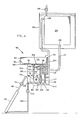
- a solar powered engine 10 has a chamber 12 in which is located a piston 14.
- a diaphragm 16 is attached to the piston 14 to provide a gas-tight seal between the piston 14 and the interior wall of the chamber 12.
- the piston 14 is connected to a rod 18 which provides the mechanical output from the engine 10.
- the rod 18 may be connected, for example, to a reciprocating water pump.
- An inlet 20 opens into the space 22 in the chamber 12 below the piston 14.
- the valve 24 is operably linked via a linkage 32 to the piston 14.
- the valve 24 and the linkage 32 are illustrated in more detail in Figures 2 and 3.
- the linkage 32 comprises a first rod 34 which is connected to the piston 14, a second rod 36 which is connected to a valve spindle 38 and a spring 40 connecting the two rods 34 and 36.
- the valve spindle 38 alternately provides communication between the ports 26 and 28 ( Figure 2) and the ports 26 and 30 ( Figure 3).
- the rod 34 moves upwards until at the top of the stroke of the piston 14 (i.e. the second position of the piston) the rod 34 and the spring 40 cause the rod 36 to flip over which in turn causes the valve spindle 38 to rotate until the port 26 communicates with the port 30.
- the operation reverses itself so that the port 26 again communicates with the port 28.
- the valve 24 only moves from one position to the other when the piston 14 reaches either the bottom (first position) or top (second position) of its movement in the chamber 12.
- the port 28 of the valve 24 is connected to a fluid storage tank 42 via a feed line 44.
- the storage tank 42 is in turn connected to a solar collector 46 via feed lines 48 and 50.
- the port 30 of the valve 24 is connected via a feed line 52 to the vapour end 54 of condenser 56 which can be air or water cooled.
- the port 26 of the valve 24 communicates with the space 22 in the chamber 12 below the piston 14.
- the condenser 56 also has a liquid end 58 which is connected via a feed line 60 and a non-return valve 62 to a reservoir 64.
- the reservoir 64 is also connected via a feed line 66 and a non-return valve 68 to the storage tank 42.
- a vapour passage or feed line 70 is connected between the reservoir 64 above the liquid level therein, and the chamber 12 below the piston 14.
- the feed line 52 is connected to the space 72 above the piston 14 by a feed line 74.
- the liquid contained in the solar collector 46 which may be any suitable liquid such as trichlorotrifluoroethane or preferably trichloromonofluoromethane heats up and vapourises.
- the vapour builds up a pressure in the solar collector 46 and flows via the feed line 48 into the storage tank 42.
- the valve 24 Prior to, and during the build-up of vapour pressure, the valve 24 is in the position shown in Figures 1 and 2, i.e. the port 28 which is connected to the storage tank 42, is in communication with the port 26, which opens into the space 22.
- the vapourised liquid thus flows from the storage tank 42 through the ports 28 and 26 into the space 22.
- the space 22 is also connected via the feed line 70 to the reservoir 64.
- the pressure in the reservoir 64 also builds up.
- the net liquid head resulting from the difference in liquid levels of the reservoir 64 and the storage tank 42 causes the non-return valve 68 to open, permitting liquid to flow from the reservoir 64 into the storage tank 42.
- the liquid then flows from the storage tank 42 into the solar collector 46 via the feed line 50 to replenish the vapourised liquid which has flowed into the space 22.
- the non-return valve 62 remains closed.
- the linkage 32 to the valve 24 causes this valve to move so as to cut off the flow of vapour from the storage tank 42 to the space 22 (i.e. ports 26 and 28 are no longer in communication), and to connect the ports 26 and 30 so that the space 22 is in communication with the vapour end 54 of the condenser 56.
- the exhausted vapour now flows from the space 22 via the ports 26 and 30 into the feed line 52 and to the vapour end 54 of the condenser 56.
- the exhausted vapour also flows via the feed line 74 to the space 72 on the other side of the piston 14 thus equalising the pressures on either side of the piston 14.
- the exhausted vapour is condensed in the condenser 56 and flows to the liquid end of the condenser 58.
- the higher vapour pressure in the storage tank 42 than in the reservoir 64 ensures that the non-return valve 68 closes. Since the pressures on either side of the piston 14 are substantially equal, the piston 14 drops to its lower position under the influence of gravity. On reaching the lower position, the valve 24 is once again moved by the linkage 32 so that ports 28 and 26 are again in communication. The cycle now recommences.
- the engine 10 is a closed system as the liquid which is vapourised in the solar collector 46 flows into the space 22, then out of the space 22 to the condenser 56 where it is condensed and from there to the reservoir 64 and then back to the solar collector 46.
- a solar powered .engine 80 has a chamber 82 in which is located a piston 84.
- a diaphragm 86 is attached to the piston 84 to provide a gas-tight seal between the piston 84 and the interior wall of the chamber 82.
- the piston 84 is connected to a piston rod 88 which turn is connected to a chain 90 which passes over a sprocket 92.
- a shaft 94 is attached to the sprocket 92.
- Mounted on the shaft 94 is a driven pulley 96 which in turn drives, e.g. a reciprocating water pump (not shown).
- An inlet 98 opens into the space 100 in the chamber 82 below the piston 84.
- a second chamber 102 having an inlet 104 and three outlets 106, 108 and 110.
- the inlet 104 is connected via a feed line 112 and a stop valve 114 to a solar collector 116.
- the second chamber also includes a liquid outlet 118 which is connected via a feed line 120 and a stop valve 122 to the solar collector 116.
- the first outlet 106 communicates with the inlet 98 into the space 100 in the chamber 82 below the piston 84.
- the second outlet 108 is connected via a feed line 124 to a condenser 126 having a vapour end 128 and a liquid end 129.
- the liquid end 129 of the condenser 126 is connected via a feed line 131 to a storage chamber 130.
- the feed line 124 also communicates via a feed line 132 with the space 134 in the chamber 82 above the piston 84.
- the condenser 126 comprises a set of vertical sided closed containers immersed in approximately 2000 litres of water in a large tank 136.
- the closed containers may be flat sided envelopes or conventional circular drums.
- the condenser 126 utilises the heat pipe principle, since condensation takes place continuously on the water cooled inner skin of the condenser 126. As soon as the condensate forms, it drains away via feed line 131 to the storage chamber 130, drawing fresh vapourised liquid into the condenser 126 via the feed line 124.
- the latent heat of condensation rejected into the condenser skin is carried away by natural convection of the water in the tank 136, causing the water temperature to rise slowly and ultimately transfer the heat to the outside air through the walls of the tank 136.
- An evacuation manifold and valve 138 located at the highest point of the condenser 126 permits the evacuation of all trapped air from the system.
- the third outlet 110 communicates via a feed line 140 with a reservoir 142.
- the reservoir 142 is connected via a feed line 144 and a non-return valve 146 to the storage chamber 130 and also via a feed line 148 and a non-return valve 150 to the second chamber 102.
- valve 152 Located in the second chamber 102 is a valve 152 which will be described in more detail with reference to Figures 5 and 6.
- the valve 152 comprises a frame 154 mounted in the second chamber 102 and having three openings therein corresponding to the three outlets 106, 108 and 110.
- a carriage 156 is supported for movement on two rails 158 which are mounted in the frame 154.
- a cup-shaped sliding member 160 is coupled to the carriage 156 by a lug 162 and is lightly pre-loaded against the interior surface 164 of the frame 154 by springs 166.
- a compression spring 168 Encased in the carriage 156 is a compression spring 168 and two spring followers 170 and 172, and located at either end of the carriage 156 are two pairs of stops 174 and 176 respectively.
- Protruding into the carriage 156, on either end of the spring 168, are two driving pins 178 and 180 which are fixedly attached to the piston rod 88.
- latches 184 and 186 Mounted on a support bar 182 which is attached to the frame 154, are two latches 184 and 186 which are mounted for rotation about pivot pins 188 and 190 respectively.
- the latches 184 and 186 act against two stops 192 and 194 respectively which are attached to the . carriage 156.
- the latches 184 and 186 are pre-loaded into their locked position by means of latch springs 196 and 198 respectively.
- the driving pins 178 and 180 move up and down in the carraige 156 on movement of the piston 84 and piston rod 88, and cause up and down movement of the carriage 156 and hence the sliding member 160, between a first position when the outlet 108 is brought into communication with the outlet 110, and a second position in which the outlet 106 is brought into communication with the outlet 108.
- the up and down directions are illustrated by arrows.
- valve 152 The exact operation of the valve 152 will now be described.
- the valve 152 is shown in Figures 5 and 6 in its second position, with the sliding member 160 bringing the outlets 106 and 108 into communication.
- the latch 184 is locked against the stop 192 thus preventing the carriage 156 from moving down.
- the driving pins 178 and 180 carry the spring 168 with them downwards, leaving the carriage 156 locked in is second position.
- the spring follower 172 contacts the stops 176 preventing further movement of the spring follower 172.
- the driving pin 178 continues to move downwards compressing the spring 168 until the driving pin 178 reaches the latch 184, which it then rotates in a counter-clockwise direction causing it to unlatch from the stop 192.
- the carriage 156 and the sliding member 160 are then driven by the compressed spring 168 downward to the first position, thus bringing the outlets 108 and 110 into communication.
- the driving pin 180 picks up the spring follower 172 before the carriage 156 strikes the frame 154 minimising any carriage/frame impact shock. With the carriage 156 in its first position, the latch spring 198 rotates the latch 186 into its locked position against the stop 194, thus locking the carriage 156 in this position.
- the piston 84 now rises and the spring 168 and the spring followers 170 and 172 are carried upwards by the driving pins 178 and 180 until the spring follower 170 contacts the stops 174.
- the spring 168 is now compressed in the upward direction until the latch 186 is unlatched by the driving pin 180 and the carriage 156 and the sliding member 160 are driven upward by the compressed spring 168. This completes a full cycle of the valve 152.
- the piston 84 is in its first low position in the chamber 82, the valve 152 is in its first position with the inlet 104 in communication with the outlet 106, and the two outlets 108 and 110 in communication, and the stop valve 114 is open (all as shown in Figure 4).
- Solar energy falling on the solar collector 116 causes the liquid therein, which may be e.g. trichlorotrifluoroethane or trichloromonofluoromethane, to vapourise.
- the vapourised liquid flows via the feed line 112 into the second chamber 102 and via the outlet 106 into the inlet 98 communicating with the space 100 below the piston 84.
- the valve 1 52 moves to its second position as previously described, thus bringing the outlets 108 and 106 into communication, with the inlet 104 now being in communication with the outlet 110.
- the vapourised liquid under the piston 84 flows out of the inlet 98 into the outlet 106 and thence to the vapour end 128 of the condenser 126, and to the space 134 above the piston 84.
- the vapourised liquid is condensed in the condenser 126 and flows to the storage chamber 130 from the liquid end 129 of the condenser 126 via the feed line 131.
- the piston 84 descends in the chamber 82 under the influence of gravity, back to its first position.
- the pressures in the solar collector 116 and second chamber' 102 and the reservoir 142 are equalised.
- the difference in liquid levels in the second chamber 102 and the reservoir 142 causes the non-return valve 150 to open so that liquid flows from the reservoir 142 via the feed line 148 into the second chamber 102 and from there via the feed line 120 back to the solar collector 116.
- the non-return valve 146 remains closed.
- the valve 152 moves back to its first position and the cycle is repeated. If it is desired to stop the operation of the engine 80, the stop valve 114 is closed.
- the engine 80 also forms a closed system with the liquid which is vapourised in the solar collector being condensed and then returned thereto.
Landscapes
- Engineering & Computer Science (AREA)
- Chemical & Material Sciences (AREA)
- Combustion & Propulsion (AREA)
- Mechanical Engineering (AREA)
- General Engineering & Computer Science (AREA)
- Life Sciences & Earth Sciences (AREA)
- Sustainable Development (AREA)
- Sustainable Energy (AREA)
- Water Supply & Treatment (AREA)
- Physics & Mathematics (AREA)
- Thermal Sciences (AREA)
- Control Of The Air-Fuel Ratio Of Carburetors (AREA)
- Photovoltaic Devices (AREA)
- Lubrication Of Internal Combustion Engines (AREA)
- Engine Equipment That Uses Special Cycles (AREA)
- Catching Or Destruction (AREA)
- Luminescent Compositions (AREA)
- Pharmaceuticals Containing Other Organic And Inorganic Compounds (AREA)
- Heat Treatment Of Water, Waste Water Or Sewage (AREA)
- Transition And Organic Metals Composition Catalysts For Addition Polymerization (AREA)
- Control Of Electric Motors In General (AREA)
- Electric Propulsion And Braking For Vehicles (AREA)
- Arrangement Or Mounting Of Propulsion Units For Vehicles (AREA)
- Electromechanical Clocks (AREA)
Priority Applications (1)
| Application Number | Priority Date | Filing Date | Title |
|---|---|---|---|
| AT82306063T ATE12045T1 (de) | 1981-11-16 | 1982-11-15 | Sonnenkraftmaschine. |
Applications Claiming Priority (2)
| Application Number | Priority Date | Filing Date | Title |
|---|---|---|---|
| ZA817915 | 1981-11-16 | ||
| ZA817915 | 1981-11-16 |
Publications (2)
| Publication Number | Publication Date |
|---|---|
| EP0079789A1 EP0079789A1 (en) | 1983-05-25 |
| EP0079789B1 true EP0079789B1 (en) | 1985-03-06 |
Family
ID=25575758
Family Applications (1)
| Application Number | Title | Priority Date | Filing Date |
|---|---|---|---|
| EP82306063A Expired EP0079789B1 (en) | 1981-11-16 | 1982-11-15 | Solar powered engine |
Country Status (13)
| Country | Link |
|---|---|
| US (1) | US4471617A (https=) |
| EP (1) | EP0079789B1 (https=) |
| JP (1) | JPS58131375A (https=) |
| AT (1) | ATE12045T1 (https=) |
| AU (1) | AU9063282A (https=) |
| BR (1) | BR8206599A (https=) |
| DE (1) | DE3262502D1 (https=) |
| ES (1) | ES8401228A1 (https=) |
| GR (1) | GR77762B (https=) |
| IL (1) | IL67225A0 (https=) |
| MW (1) | MW4682A1 (https=) |
| PT (1) | PT75824B (https=) |
| ZW (1) | ZW24582A1 (https=) |
Families Citing this family (15)
| Publication number | Priority date | Publication date | Assignee | Title |
|---|---|---|---|---|
| FR2519693B2 (fr) * | 1982-01-14 | 1989-10-13 | Sorelec | Moteur a conversion thermomecanique, notamment moteur a fluide a basse temperature d'ebullition |
| FR2516593B1 (fr) * | 1981-11-19 | 1989-08-18 | Sorelec | Moteur a conversion thermo-mecanique notamment moteur a fluide a basse temperature d'ebullition |
| GB8525850D0 (en) * | 1985-10-19 | 1985-11-20 | Save The Children | Pump |
| US4884953A (en) * | 1988-10-31 | 1989-12-05 | Ergenics, Inc. | Solar powered pump with electrical generator |
| JPH0430236U (https=) * | 1990-07-03 | 1992-03-11 | ||
| ES2114759B1 (es) * | 1994-03-14 | 1999-02-01 | Cusido Vallmitjana J | Sistema de bombeo impulsado por energia solar. |
| DE4409197A1 (de) * | 1994-03-17 | 1995-09-21 | Siemens Ag | Verfahren und Einrichtung zur solaren Dampferzeugung |
| US5461858A (en) * | 1994-04-04 | 1995-10-31 | Energy Conversation Partnership, Ltd. | Method of producing hydroelectric power |
| GB2352276B (en) * | 1996-09-08 | 2002-04-10 | Goldenblum Haim | Method,device and system for converting environmental heat into usable energy |
| US8065876B2 (en) * | 2005-09-21 | 2011-11-29 | Solartrec Inc. | Heat engine improvements |
| US7536861B2 (en) * | 2005-09-21 | 2009-05-26 | Solartrec Inc. | Solar heat engine system |
| US20070101989A1 (en) * | 2005-11-08 | 2007-05-10 | Mev Technology, Inc. | Apparatus and method for the conversion of thermal energy sources including solar energy |
| US20090134004A1 (en) * | 2007-11-27 | 2009-05-28 | Asprey William J | Driving or driven distiller with heat pump function |
| US9664180B2 (en) * | 2014-02-28 | 2017-05-30 | John A. Saavedra | Power generating system utilizing expanding liquid |
| US11767824B2 (en) | 2014-02-28 | 2023-09-26 | Look For The Power Llc | Power generating system utilizing expanding fluid |
Family Cites Families (6)
| Publication number | Priority date | Publication date | Assignee | Title |
|---|---|---|---|---|
| FR837406A (fr) * | 1937-04-30 | 1939-02-09 | Procédé hydrostatique d'alimentation des chaudières à vapeur et dispositif d'alimentation des chaudières d'après ce procédé | |
| FR934256A (fr) * | 1946-09-17 | 1948-05-18 | Appareil moteur utilisant l'énergie solaire | |
| US3790305A (en) * | 1972-11-28 | 1974-02-05 | A Ledner | Thermal-gravity fluid pumping method and apparatus |
| AR219049A1 (es) * | 1975-07-24 | 1980-07-31 | Tacchi V | Combinacion de un captador de energia solar y disposicion orientadora para el mismo |
| US4180982A (en) * | 1977-03-21 | 1980-01-01 | Israel Siegel | Instant return-stroke differential temperature engine |
| FR2428157A1 (fr) * | 1978-06-05 | 1980-01-04 | Paris Ecole Nale Sup Arts Meti | Moteur solaire sans piston ni lubrification |
-
1982
- 1982-11-08 US US06/439,781 patent/US4471617A/en not_active Expired - Fee Related
- 1982-11-10 ZW ZW245/82A patent/ZW24582A1/xx unknown
- 1982-11-10 PT PT75824A patent/PT75824B/pt unknown
- 1982-11-10 IL IL67225A patent/IL67225A0/xx unknown
- 1982-11-12 MW MW46/82A patent/MW4682A1/xx unknown
- 1982-11-12 BR BR8206599A patent/BR8206599A/pt unknown
- 1982-11-15 DE DE8282306063T patent/DE3262502D1/de not_active Expired
- 1982-11-15 GR GR69818A patent/GR77762B/el unknown
- 1982-11-15 AT AT82306063T patent/ATE12045T1/de not_active IP Right Cessation
- 1982-11-15 JP JP57200253A patent/JPS58131375A/ja active Pending
- 1982-11-15 EP EP82306063A patent/EP0079789B1/en not_active Expired
- 1982-11-16 AU AU90632/82A patent/AU9063282A/en not_active Abandoned
- 1982-11-16 ES ES517414A patent/ES8401228A1/es not_active Expired
Also Published As
| Publication number | Publication date |
|---|---|
| AU9063282A (en) | 1983-05-26 |
| MW4682A1 (en) | 1984-09-12 |
| US4471617A (en) | 1984-09-18 |
| ZW24582A1 (en) | 1983-03-09 |
| EP0079789A1 (en) | 1983-05-25 |
| BR8206599A (pt) | 1983-10-04 |
| JPS58131375A (ja) | 1983-08-05 |
| ES517414A0 (es) | 1983-11-16 |
| GR77762B (https=) | 1984-09-25 |
| PT75824A (en) | 1982-12-01 |
| DE3262502D1 (en) | 1985-04-11 |
| ES8401228A1 (es) | 1983-11-16 |
| IL67225A0 (en) | 1983-03-31 |
| PT75824B (en) | 1985-01-09 |
| ATE12045T1 (de) | 1985-03-15 |
Similar Documents
| Publication | Publication Date | Title |
|---|---|---|
| EP0079789B1 (en) | Solar powered engine | |
| US4103490A (en) | Apparatus for harnessing tidal power | |
| US3925986A (en) | Air engine | |
| US4583368A (en) | Water-powered hydraulic motor | |
| US4698973A (en) | Closed loop solar collector system powering a self-starting uniflow engine | |
| US7194861B2 (en) | Two stroke steam-to-vacuum engine | |
| US1290203A (en) | Hydraulic motor for hay-presses. | |
| US4783961A (en) | Natural gas pressure differential energy recovery system | |
| US4149383A (en) | Internal vaporization engine | |
| US4270351A (en) | Heat engine and thermodynamic cycle | |
| US4156343A (en) | Power generating assembly | |
| US4372123A (en) | Thermal-gravity engine | |
| DE3133387C2 (de) | Lösungspumpe zur Erhöhung des Kälte- oder Lösungsmitteldruckes in Absorptionswärmepumpen | |
| US1294271A (en) | Method and apparatus for raising or forcing liquids. | |
| SU1553801A1 (ru) | Гелиоводоподъемное устройство | |
| US4314447A (en) | Refrigerant motor | |
| US3956893A (en) | Hydraulic power transmission | |
| US1334281A (en) | Storage and utilization of energy by means of liquids | |
| US4788823A (en) | Valve mechanism for controlling a reciprocating engine power stroke | |
| WO1985000855A1 (en) | Closed loop solar collector system powering a self-starting uniflow steam engine | |
| US4627241A (en) | Closed loop solar collector system powering a self-starting uniflow steam engine | |
| RU2011019C1 (ru) | Кессонный насос | |
| US1203335A (en) | Air-compressor. | |
| US230149A (en) | powers | |
| US340031A (en) | csete |
Legal Events
| Date | Code | Title | Description |
|---|---|---|---|
| PUAI | Public reference made under article 153(3) epc to a published international application that has entered the european phase |
Free format text: ORIGINAL CODE: 0009012 |
|
| AK | Designated contracting states |
Designated state(s): AT BE CH DE FR GB IT LI LU NL SE |
|
| 17P | Request for examination filed |
Effective date: 19830523 |
|
| ITF | It: translation for a ep patent filed | ||
| GRAA | (expected) grant |
Free format text: ORIGINAL CODE: 0009210 |
|
| AK | Designated contracting states |
Designated state(s): AT BE CH DE FR GB IT LI LU NL SE |
|
| REF | Corresponds to: |
Ref document number: 12045 Country of ref document: AT Date of ref document: 19850315 Kind code of ref document: T |
|
| REF | Corresponds to: |
Ref document number: 3262502 Country of ref document: DE Date of ref document: 19850411 |
|
| ET | Fr: translation filed | ||
| PG25 | Lapsed in a contracting state [announced via postgrant information from national office to epo] |
Ref country code: LU Free format text: LAPSE BECAUSE OF NON-PAYMENT OF DUE FEES Effective date: 19851130 |
|
| PLBE | No opposition filed within time limit |
Free format text: ORIGINAL CODE: 0009261 |
|
| STAA | Information on the status of an ep patent application or granted ep patent |
Free format text: STATUS: NO OPPOSITION FILED WITHIN TIME LIMIT |
|
| 26N | No opposition filed | ||
| ITTA | It: last paid annual fee | ||
| PGFP | Annual fee paid to national office [announced via postgrant information from national office to epo] |
Ref country code: NL Payment date: 19891130 Year of fee payment: 8 |
|
| PGFP | Annual fee paid to national office [announced via postgrant information from national office to epo] |
Ref country code: FR Payment date: 19891222 Year of fee payment: 8 Ref country code: DE Payment date: 19891222 Year of fee payment: 8 |
|
| PGFP | Annual fee paid to national office [announced via postgrant information from national office to epo] |
Ref country code: BE Payment date: 19891227 Year of fee payment: 8 |
|
| PGFP | Annual fee paid to national office [announced via postgrant information from national office to epo] |
Ref country code: AT Payment date: 19891231 Year of fee payment: 8 |
|
| PGFP | Annual fee paid to national office [announced via postgrant information from national office to epo] |
Ref country code: SE Payment date: 19900102 Year of fee payment: 8 |
|
| PGFP | Annual fee paid to national office [announced via postgrant information from national office to epo] |
Ref country code: CH Payment date: 19900126 Year of fee payment: 8 |
|
| PGFP | Annual fee paid to national office [announced via postgrant information from national office to epo] |
Ref country code: LU Payment date: 19900131 Year of fee payment: 8 Ref country code: GB Payment date: 19900131 Year of fee payment: 8 |
|
| REG | Reference to a national code |
Ref country code: FR Ref legal event code: ST |
|
| PG25 | Lapsed in a contracting state [announced via postgrant information from national office to epo] |
Ref country code: GB Effective date: 19901115 Ref country code: AT Effective date: 19901115 |
|
| PG25 | Lapsed in a contracting state [announced via postgrant information from national office to epo] |
Ref country code: SE Effective date: 19901116 |
|
| REG | Reference to a national code |
Ref country code: FR Ref legal event code: DA |
|
| PG25 | Lapsed in a contracting state [announced via postgrant information from national office to epo] |
Ref country code: LI Effective date: 19901130 Ref country code: CH Effective date: 19901130 Ref country code: BE Effective date: 19901130 |
|
| BERE | Be: lapsed |
Owner name: GRINAKER EQUIPMENT CY. (PROPRIETARY) LTD Effective date: 19901130 |
|
| PG25 | Lapsed in a contracting state [announced via postgrant information from national office to epo] |
Ref country code: NL Effective date: 19910601 |
|
| GBPC | Gb: european patent ceased through non-payment of renewal fee | ||
| NLV4 | Nl: lapsed or anulled due to non-payment of the annual fee | ||
| PG25 | Lapsed in a contracting state [announced via postgrant information from national office to epo] |
Ref country code: FR Free format text: LAPSE BECAUSE OF NON-PAYMENT OF DUE FEES Effective date: 19910731 |
|
| REG | Reference to a national code |
Ref country code: CH Ref legal event code: PL |
|
| PG25 | Lapsed in a contracting state [announced via postgrant information from national office to epo] |
Ref country code: DE Effective date: 19910801 |
|
| REG | Reference to a national code |
Ref country code: FR Ref legal event code: ST |
|
| EUG | Se: european patent has lapsed |
Ref document number: 82306063.7 Effective date: 19910705 |