EP0078672B1 - Eddy current hot pipe flaw detection - Google Patents
Eddy current hot pipe flaw detection Download PDFInfo
- Publication number
- EP0078672B1 EP0078672B1 EP82305748A EP82305748A EP0078672B1 EP 0078672 B1 EP0078672 B1 EP 0078672B1 EP 82305748 A EP82305748 A EP 82305748A EP 82305748 A EP82305748 A EP 82305748A EP 0078672 B1 EP0078672 B1 EP 0078672B1
- Authority
- EP
- European Patent Office
- Prior art keywords
- shield
- workpiece
- coolant liquid
- path
- coolant
- Prior art date
- Legal status (The legal status is an assumption and is not a legal conclusion. Google has not performed a legal analysis and makes no representation as to the accuracy of the status listed.)
- Expired
Links
- 238000001514 detection method Methods 0.000 title claims description 24
- 238000012360 testing method Methods 0.000 claims description 67
- 239000002826 coolant Substances 0.000 claims description 57
- 239000007788 liquid Substances 0.000 claims description 32
- 238000000034 method Methods 0.000 claims description 15
- 239000012530 fluid Substances 0.000 claims description 10
- XLYOFNOQVPJJNP-UHFFFAOYSA-N water Substances O XLYOFNOQVPJJNP-UHFFFAOYSA-N 0.000 description 17
- 238000004382 potting Methods 0.000 description 15
- 238000001816 cooling Methods 0.000 description 12
- 239000000523 sample Substances 0.000 description 9
- 238000007689 inspection Methods 0.000 description 8
- 229910000831 Steel Inorganic materials 0.000 description 6
- 230000005284 excitation Effects 0.000 description 6
- 239000010959 steel Substances 0.000 description 6
- 238000004519 manufacturing process Methods 0.000 description 5
- 239000000203 mixture Substances 0.000 description 5
- 238000010926 purge Methods 0.000 description 5
- 150000001875 compounds Chemical class 0.000 description 4
- 238000011010 flushing procedure Methods 0.000 description 4
- 229920001971 elastomer Polymers 0.000 description 3
- 239000010935 stainless steel Substances 0.000 description 3
- 229910001220 stainless steel Inorganic materials 0.000 description 3
- VVQNEPGJFQJSBK-UHFFFAOYSA-N Methyl methacrylate Chemical compound COC(=O)C(C)=C VVQNEPGJFQJSBK-UHFFFAOYSA-N 0.000 description 2
- 229920005372 Plexiglas® Polymers 0.000 description 2
- 230000001939 inductive effect Effects 0.000 description 2
- 238000012545 processing Methods 0.000 description 2
- 230000004044 response Effects 0.000 description 2
- 230000035945 sensitivity Effects 0.000 description 2
- 229910000975 Carbon steel Inorganic materials 0.000 description 1
- 230000002411 adverse Effects 0.000 description 1
- 230000004075 alteration Effects 0.000 description 1
- 239000010962 carbon steel Substances 0.000 description 1
- 238000010276 construction Methods 0.000 description 1
- 230000002596 correlated effect Effects 0.000 description 1
- 230000002950 deficient Effects 0.000 description 1
- 230000002939 deleterious effect Effects 0.000 description 1
- 238000009826 distribution Methods 0.000 description 1
- 230000000694 effects Effects 0.000 description 1
- 230000008030 elimination Effects 0.000 description 1
- 238000003379 elimination reaction Methods 0.000 description 1
- 230000001771 impaired effect Effects 0.000 description 1
- 238000012423 maintenance Methods 0.000 description 1
- 230000007257 malfunction Effects 0.000 description 1
- 239000000463 material Substances 0.000 description 1
- 238000005259 measurement Methods 0.000 description 1
- 239000002184 metal Substances 0.000 description 1
- 238000012986 modification Methods 0.000 description 1
- 230000004048 modification Effects 0.000 description 1
- 238000013021 overheating Methods 0.000 description 1
- 229920001084 poly(chloroprene) Polymers 0.000 description 1
- 230000008569 process Effects 0.000 description 1
- 238000005086 pumping Methods 0.000 description 1
- 230000009467 reduction Effects 0.000 description 1
- 229920006395 saturated elastomer Polymers 0.000 description 1
- 238000004513 sizing Methods 0.000 description 1
- 238000005507 spraying Methods 0.000 description 1
- 238000003466 welding Methods 0.000 description 1
Images


Classifications
-
- G—PHYSICS
- G01—MEASURING; TESTING
- G01N—INVESTIGATING OR ANALYSING MATERIALS BY DETERMINING THEIR CHEMICAL OR PHYSICAL PROPERTIES
- G01N27/00—Investigating or analysing materials by the use of electric, electrochemical, or magnetic means
- G01N27/72—Investigating or analysing materials by the use of electric, electrochemical, or magnetic means by investigating magnetic variables
- G01N27/82—Investigating or analysing materials by the use of electric, electrochemical, or magnetic means by investigating magnetic variables for investigating the presence of flaws
- G01N27/90—Investigating or analysing materials by the use of electric, electrochemical, or magnetic means by investigating magnetic variables for investigating the presence of flaws using eddy currents
- G01N27/9006—Details, e.g. in the structure or functioning of sensors
-
- Y—GENERAL TAGGING OF NEW TECHNOLOGICAL DEVELOPMENTS; GENERAL TAGGING OF CROSS-SECTIONAL TECHNOLOGIES SPANNING OVER SEVERAL SECTIONS OF THE IPC; TECHNICAL SUBJECTS COVERED BY FORMER USPC CROSS-REFERENCE ART COLLECTIONS [XRACs] AND DIGESTS
- Y10—TECHNICAL SUBJECTS COVERED BY FORMER USPC
- Y10S—TECHNICAL SUBJECTS COVERED BY FORMER USPC CROSS-REFERENCE ART COLLECTIONS [XRACs] AND DIGESTS
- Y10S165/00—Heat exchange
- Y10S165/903—Convection
Definitions
- each detector coil 40 is wound around a coil form 44 having square cross sectioned ends, and defining recessed cylindrically cross-sectioned intermediate portions about which the coil itself is wound.
- Each probe coil from bears terminals of known type forming interconnection points to which the probe coil ends are attached.
- These forms 44 are then positioned about a sleeve-like probe coil potting form (not shown) and glued at their ends to an annular probe coil assembly ring 46 ( Figure 13) which is positioned coaxial to the heat shield, and which is preferably also made of plexiglass.
- the potting form has an outside diameter equal to the outside diameter of the stepped portion ( Figure 6) defined by the lip 47 of the heat shield 24.
Landscapes
- Chemical & Material Sciences (AREA)
- Chemical Kinetics & Catalysis (AREA)
- Electrochemistry (AREA)
- Physics & Mathematics (AREA)
- Health & Medical Sciences (AREA)
- Life Sciences & Earth Sciences (AREA)
- Analytical Chemistry (AREA)
- Biochemistry (AREA)
- General Health & Medical Sciences (AREA)
- General Physics & Mathematics (AREA)
- Immunology (AREA)
- Pathology (AREA)
- Investigating Or Analyzing Materials By The Use Of Magnetic Means (AREA)
Description
- The. present invention relates to hot pipe flaw detection and more particularly to an improved method and apparatus for liquid cooling and flushing of eddy current flaw detection equipment.
- In the manufacture of metal products such as pipe, it is desirable to inspect for flaws or imperfections as the product is manufactured. According to current manufacturing techniques, some inspection is done by or with the assistance of some type of automated detecting apparatus. Several widely used testing techniques utilize eddy current flaw detectors.
- In one type of eddy current detector, an oscillating power source energizes an excitation coil for inducing eddy current flow in a workpiece under inspection. A detection assembly including detection, or probe, coils, as well as the exciter coil, is positioned in proximity to the workpiece and relative movement imparted between workpiece and assembly. Flaws are sensed by the detection coils' response to variation in the eddy current flow due to inhomogeneity in the flawed region. As flaws are located their positions are marked and typically steps are also undertaken to prevent further flaws from occurring.
- In a typical system each detector assembly has one or more detecting coils, and both these and the exciter coil are inductively coupled with the workpiece. The exciter coil induces eddy currents, as noted above. The detection coils produce distinctive output signals in response to variations in eddy current flow within the workpiece. These variations are casued by flaws, such as cracks, in the workpiece which interfere with eddy current flow to an extent related to the severity (lengh and depth) of the flaw. Accordingly, variations in output signals from a detection coil can be correlated to the existence, length and depth of flaws in the workpice.
- Eddy current testing systems have been used to monitor some welded steel pipe or bar stock immediately after manufacture while still hot, which is desirable, for reasons explained below. Because of overheating of eddy current test apparatus, caused by the hot product, some steel pipe could not be inspected while hot.
- It is particularly advantageous to inspect the pipe as soon as possible after manufacture. With present high speed pipe fabricating machinery, welded pipe can be produced at speeds of the order of 488 metres (1,600 ft.) of pipe per minute. If a pipe welder is malfunctioning, causing flaws in the product, and the pipe cannot be inspected before cooling, literally kilometres of defective pipe may be fabricated before flaw inspection techniques reveal the existence of the malfunction in the welder.
- The inspection apparatus disclosed in United States Patent No. 4,024,470, to Vild et al, issued May 17, 1977, under the title "Eddy Current Detector for Hot Test Process Having Coolant Fluid and Purge Features" provided a hot pipe inspection technique unknown in the earlier art. This patent has been assigned to the Republic Steel Corporation, assignee of the present invention and is expressly incorporated now by reference.
- Apparatus disclosed in the patent US-A-4024470 overcame difficulties experienced in prior art eddy current testers by using water to both cool the detection apparatus and purge from the detector debris, such as scale and dirt, which accumulates during testing. Although representing a significant advancement in the art, use of the apparatus disclosed in the patent US-A-4 024 470 gave rise to unexpected difficulties, especially with relatively small diameter pipe, which previously had been the easiest to test while hot.
- As pointed out in the Vild et al patent, typical prior art inspection apparatus included both an exciter coil and a saturation coil which surrounded a workpiece path of travel. The saturation coil magnetically saturated the workpiece to improve the sensitivity of the eddy current testing. It was found, however, that if a steel pipe is tested at a temperature above its Curie point, (approximately 768°C (1415°F) for carbon steel) the saturation coil can be eliminated because the pipe is no longer magnetic. Thus, it was found that eddy current test apparatus could be significantly simplified if appropriate steps were taken to test at a temperature above the Curie point.
- The purging and cooling techniques disclosed in the Vild et al patent involve directing water onto the pipe in the vicinity of the test head assembly. This was an effective technique for flushing debris from the vicinity of the test head, but it has also been discovered that sometimes application of the flushing water caused localized cooling of the pipe to a temperature below the Curie point. When this occurred the eddy current tester output signals became noisy and the utility of the eddy current test was impaired. The Vild et al apparatus is thus effective in cooling the eddy current coil assembly and in removing debris from the sensitive area of the coil assembly but unfortunately can cause an unexpected loss in testing effectiveness by cooling the steel workpiece below its Curie point.
- Another problem with the device of the patent US-A-4 024 470 was that the coolant was forced through a partially closed annular chamber defined by structure in the test assembly between the coils and the pipe. The pressure of this chamber necessitated a pipe to coil spacing large enough to accommodate the structure, which spacing limited test sensitivity.
- US-A-4 024 470 also illustrates in Figures 5 and 6 thereof a coolant tube which extends longitudinally along the heat shield and which has nozzle holes for spraying coolant liquid. The position of the nozzles holes, as illustrated in Figure 6, make it clear that the coolant liquid is directed substantially horizontally to the left from the coolant tube as illustrated in Figure 5. While this construction may be employed to drop coolant on the upper surface of the heat shield, as when low pressure is used, it is obvious that, when one rotates the embodiment of Figures 5 and 6 about a circular path circumscribing a workpiece, it will be impossible to keep coolant liquid from being sprayed directly on, or dripping upon, the workpiece surface. The fluid is directed simply in a circumferential direction about the pipe.
- The present invention provides for fluid purging and cooling of eddy current hot pipe testing apparatus while assuring against undesirable cooling of the pipe workpiece itself. The apparatus enables hot pipe testing without the necessity for providing a saturation coil, inasmuch as a properly cooled and purged test head is provided which does not also reduce hot pipe workpiece temperature below its Curie point.
- According to a first aspect of the present invention, there is provided an apparatus for testing a hot metallic workpiece relatively movable along a path with respect to said apparatus, said apparatus including a shield member having a surface generally facing and directly exposed to the path and disposed proximate to the path, and eddy current detection unit mounted opposite the shield with respect to the path for testing the workpiece as it moves along the path in the region of the shield, a structure which, in use, is coupled to a source of coolant liquid and directs said coolant liquid onto said workpiece-facing surface of the shield wherein said coolant directing structure includes means directing the coolant liquid onto the workpiece-facing surface of the shield and causing the coolant liquid to flow upon and cool the shield, characterised in that said means is arranged to cause the coolant liquid to subsequently flow off the shield substantially without contacting the workpiece.
- According to a second aspect of the present invention, there is provided a method for testing a hot metallic workpiece, said method including the steps of moving the workpiece along a path relative to a test apparatus including a shield member having a surface generally facing and directly exposed to the path, testing the workpiece using an eddy current detection unit as it moves along the path in the region of the shield, and directing a liquid coolant onto said workpiece facing surface of the shield by using a structure coupled, in use, to a source of coolant liquid wherein said coolant liquid directing step comprises directing the coolant liquid onto the workpice facing surface of the shield for causing the coolant liquid to flow upon and cool the shield surface, characterised in that said coolant liquid is caused by said structure to subsequently flow off the shield substantially without contacting the workpiece.
- The present invention thus provides for directing coolant fluid onto the interior surface of the shield, but substantially without impingement on the hot workpiece being tested. The apparatus according to this invention provides for cooling of the eddy current detection unit and of the heat shield member, and for purging or flushing from the inside of the shielding sleeve material such as scale and other debris, which accumulates during testing. All this is accomplished without appreciably lowering the temperature of the workpiece, such that, where the hot pipe enters the testing unit at above its Curie temperature, the need for a saturation coil is obviated.
- In accordance with a more specific aspect of the present invention, the test head assembly includes a generally tubular shield member defining an inner surface sufficiently large to accommodate passage of the pipe workpiece therethrough, and encircling the path of the pipe. An eddy current detection coil is located outside, but proximate, the inner tubular structure, as is an exciter coil for inducing eddy currents in the workpiece. Both the excitation and the detection of eddy current flow is conducted by means of electromagnetic energy passing through the inner tubular structure between the coils and the pipe workpiece moving through the test head assembly. Housing structure, in cooperation with the inner structure, encloses the coils within a generally annular chamber.
- The housing structure defines an inlet channel suitable for communicating with a source of coolant fluid for pumping the coolant into the chamber to effect cooling of the coils located within the chamber. The inner member defines outlet ports or apertures communicating between the inside of the chamber and the interior region of the shield.
- The apertures defined by the inner member are oriented to direct coolant fluid from the chamber into the interior region of the shield, in a direction which is nonradial with respect to the pipe workpiece passing through the test assembly.
- More specifically, and in accordance with a preferred embodiment of the invention, the apertures in the shield direct fluid about the inner surface of the shield in a direction which is approximately tangential with respect to that inner surface. In this way, fluid exiting from the chamber through the shield apertures is induced to flow in a generally spiral flow path along the interior surface, until reaching one end of the shield, at which point it exits the shield.
- This preferred embodiment can thus be seen to direct coolant flow along the inner surface of the shield, with substantially no impingement of the coolant on the pipe workpiece itself. The pipe remains in a hot condition, above its Curie temperature, during testing, while the test assembly is purged and kept relatively cool by the coolant flow. Additionally, the flow of coolant about the interior surface of the shield enhances heat shielding of the test apparatus from the hot workpiece passing through it.
- In the preferred embodiment, the test head includes a generally cylindrical stainless steel inner heat shield which surrounds a portion of a pipe test path and has an inside diameter larger than the outside diameter of the pipe to be tested. Accordingly, the shield defines a passageway for a pipe being tested. The shield also defines apertures through which water flows to cool the inner surface of the shield and remove debris and foreign matter from the vicinity of the detection coils without significantly contacting the pipe and thereby reducing its temperature.
- Preferably the coolant flow of the present invention is utilized in conjunction with an eddy current coil assembly comprising a plurality of eddy current detection coils and a singular annular excitation coil. Both excitation coil and detection coils are mounted within a chamber defined by the heat shield and housing structure and containing potting compounds.
- The preferred test head housing structure includes two end plates spaced apart from each other and attached to the heat shield. One end plate has a fitting for receiving the coolant and directing it to a longitudinal bore in potting compound located around the coil assembly. A radially extending passage connects the bore with an annular coolant distributor region adjacent the heat shield which communicates with the spiral flow apertures. These apertures comprise bores formed through the shield.
- Thus, the water enters the distribution region from the potting compound bore and flows through the test head passage to exit through the apertures in a moving spiralling pattern along the inner surface of the shield. This pattern results in the maintenance of a spiralling sheet of coolant encircling the pipe over the entire inner surface without touching the pipe itself. Centrifugal force maintains the coolant in contact with the heat shield as it spirals about the pipe.
- The novel flow pattern produced so effectively cools and shields the inner member that the annular chamber between the detector coils and the heat shield, as taught in the patent US-A-4 024 470 has been eliminated. Elimination of the annular flow chamber permits the detector to workpiece distance to be reduced and thereby enhances detector performance.
- From the above it is apparent that one feature and object of the present invention is the provision of method and apparatus aimed at both cooling an eddy current test head and removing debris from the vicinity of the test head while avoiding deleterious temperature reductions of the workpiece being tested. This and other advantageous features achieved through practice of the present invention will become better understood when the accompanying drawings are considered in conjunction with the detailed description which follows.
-
- Figure 1 is a partially sectioned perspective view of a pipe processing station including pipe flaw detection apparatus.
- Figure 2 is a schematic elevation view of a detector test head mounted about a pipe.
- Figure 3 is a sectioned side elevation view of the test head shown in Figure 2.
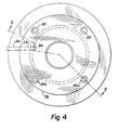
- Figure 4 is an end elevation view of the test head of Figure 2.
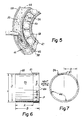
- Figure 5 is a cross sectional view, partly broken away, of the test head taken along the line 5-5 in Figure 3.
- Figures 6 and 7 are detailed elevational and end .views, respectively, of a portion of the test head of Figure 3.
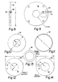
- Figures 8-14 are detailed plan and elevation views of a number of components of the test head of Figure 3.
- Turning now to the drawings, Figures 1 and 2 show a
pipe processing station 10 including pipe inspection apparatus embodying the present invention and comprising a series of roll stands 12 through which a hot pipe 14 passes soon after it has been fabricated. Thestation 10 is particularly suited for inspecting steel pipe at a temperature above its Curie temperature. - Inside the roll stands 12 at spaced locations along the pipe's length are fixed pipe guides 16, 16a for directing the pipe 14 along the path of travel. The
guides 16, 16a are spaced apart to leavegaps 18 wheredrive rollers 20 contact the pipe and propel it through theinspection station 10. - An end pipe guide 16a positioned near an exit point of the station 10 (see Figure 2) mounts an internal eddy current detector
test head assembly 22. Thetest head 22 supports an eddycurrent excitation coil 38 and a number of detector coils 40 (Figures 2, 3, 5 and 8) in proximity to a pipe path of travel. - The detector coils sense variations in eddy currents in the pipe and correlate these variations to pipe flaw locations. These flaw locations are marked and if they occur too frequently corrective steps are taken in the pipe manufacturing procedure to reduce their incidence.
- The test head 22 (Figure 3) comprises a stainless
steel heat shield 24, configured as a cylindrical sleeve having a small step defined by a lip 47 (Figures 6 and 7). The head also comprises body or housing structure including a cylindricalouter shell 28, andannular front 26 and back 30 plates which are also made of stainless steel. Thebackplate 30 is secured to theheat shield 24 and in the preferred embodiment this is accomplished by Heliarc welding the back plate's inner surface to the heat shield's outer diameter. Interposed between theback plate 30 and theshell 28 and between theshell 28 and thefront plate 26 are twoneoprene rubber gaskets - In combination, the
heat shield 24, front andback plates outer shell 28 define an annular chamber about the pipe path of travel in which are positioned the exciter coil 38 (see Figures 3 and 5) and the detector coils 40. The detector coils 40 are positioned radially inward with respect to the exciter coil which is wound around a cylindricalexciter coil form 42 made of plexiglass (see Figure 3). Both the exciter coil and all the detector coils are cylindrically wound, with their axes positioned parallel to the travel path of the pipe. - As a first step is assembly of the
test head 22, eachdetector coil 40 is wound around acoil form 44 having square cross sectioned ends, and defining recessed cylindrically cross-sectioned intermediate portions about which the coil itself is wound. Each probe coil from bears terminals of known type forming interconnection points to which the probe coil ends are attached. Theseforms 44 are then positioned about a sleeve-like probe coil potting form (not shown) and glued at their ends to an annular probe coil assembly ring 46 (Figure 13) which is positioned coaxial to the heat shield, and which is preferably also made of plexiglass. The potting form has an outside diameter equal to the outside diameter of the stepped portion (Figure 6) defined by thelip 47 of theheat shield 24. The potting form helps position the probe coils 40 in relation to the heat shield. Probe coil interconnections are then made in known fashion and theexciter coil 38 andexciter coil form 42 are positioned around the detection coils 40. Leads to the probe coils 40 are threaded through access holes 41 drilled in the coil form 42 (Figure 5) and protected with heat shrink tubing. Theouter shell 28 is then positioned about thecoils shell 28 to the outside of the potting form is filled with apotting mixture 48. Once thepotting mixture 48 has dried, the potting form is withdrawn from the interior of the assembly. - The withdrawal of the potting form leaves an unobstructed annular chamber 49 (Figure 5) which is not filled with potting compound. The radial depth of the
chamber 49 equals the height of the step on the heat shield defined by the lip 47 (Figures 6 and 7). - A hole or passageway 50 (Figures 3 and 5) is drilled longitudinally through the dry potting mixture. The potting mixture, detection coils, and exciter coil in combination comprise a potted assembly. The
gaskets test head 22, thus assembled is inserted into the exit guide 16a, and secured to the exit guide 16a byscrews excitation coil 38 and known detection circuitry is coupled to the probe coils 40. - As seen most clearly in Figures 8 and 9, attached to the
front plate 26 is an inlet fitting 54 and an outlet fitting 56 through which water or other suitable coolant may be transmitted to thetest head 22. The inlet fitting 54 communicates with the outlet fitting 56 through apassageway 58 machined into the front plate'26. Therubber gasket 32 which contacts thefront plate 26 includes a 6.35 mm (1/4") diameter hole, aligned in registration with the outlet fitting 56, through which the outlet fitting 56 extends to communicate in alignment with thepassageway 50 which was drilled through thedry potting mixture 48. - The' -
passageway 50 extends along the lingitudinal dimension of thetest head 22 and terminates at theback plate 30, by way of a slot-like passageway 60 (Figures 3 and 14) which is formed in thesecond rubber gasket 34. Thepassage 60 leads radially inward toward the pipe path of travel. - While both
rubber gaskets heat shield 24, it should be appreciated that the second of the twogaskets 34 has an inside diameter larger than the first gasket. Due to this larger inside diameter, thesecond passageway 60 terminates to define, with the shield, anannular space 62 which completely surrounds the stepped portion of theheat shield 24, and which communicates with the inlet fitting 54 on thefront plate 26. - The three
passageways test head 22 and, in a way described below, to remove foreign matter or debris from the space between the testhead heat shield 24 and the pipe 14. Once the water (or other suitable coolant) has entered theannular space 62 surrounding the heat shield, it is forced through a series ofapertures 64 which can be seen most clearly in Figures 6 and 7. These apertures are machined into the stepped portion of the heat shield and in the preferred embodiment comprise 1.5875 mm (1/16") holes extending to the interior heat shield surface in a direction nearly tangent to the interior surface to cause water passing through the apertures to immediately contact and disperse over the surface. Theapertures 64 are also angled at about 80° from the workpiece path of travel, in the direction of the path, to give the water a modest longitudinal velocity component along the pipe movement direction and thus cause it to spiral about the inside surface of the shield (as shown by arrow Q in Figure 3) until it exits the test head near thefront plate 26. - While traversing the space between the pipe and the
heat shield 24 the water dissipates heat buildup on the heat shield, which is caused by the heat shield's close proximity to the hot pipe 14. This tends to cool thecoils apertures 64 combined with their angled orientation with respect to the pipe path of travel the water remains in contact with theheat shield 24 substantially without contacting the pipe 14. This path of water travel avoids substantial cooling of the pipe and thereby allows eddy current testing to be performed without use of a saturation coil. - The disclosed test head can be constructed for use with various diameter pipes. For use with other diameter pipes, it is possible that a different number or sizing of
apertures 64 are preferably utilized to provide sufficient coolant flow rate (taking into account coolant viscosity and available pressure) to adequately cool thetest head 22. The number of apertures chosen should be such that a spiralling sheet of water is produced along substantially the entire length of theheat shield 24. Tests have shown that fourapertures 64, equally circumferentially spaced, are appropriate for many applications. More can be added to achieve the required water flow, as specified in more detail below. - Since the disclosed
test head 22 has applicability for different size pipes, the following table is disclosed to indicate various dimension parameters used in designing thetest head 22 for different pipe. These parameters are labeled on the Figures and it should be appreciated that certain tolerances in these dimensions are acceptable in the practice of the invention. All dimensions are in units of measurement where each unit equals 25.4 mm.
- Certain empirically determined approximate minimum water flow rates are needed to generate a sheet of water along the heat shield's inner surface. In test heads 22 for scanning 12.7 mm (1/2") of 19.05 mm (3/4") diameter pipe the minimum flow is 1.89 litres (.5 gallons) per minute. For 25.4 mm (I") diameter pipe, the minimum flow is 22.7 litres (.6 gallons) per minute, and for 31.75 mm (1-1/4") or 38.1 mm (1-1/2") diameter pipe, the minimum flow rate is 26.5 litres (.7 gallons) per minute.
- While a preferred embodiment of the invention has been disclosed in detail, various modifications or alterations may be made herein without departing from the scope of the invention set forth in the appended claims.
Claims (10)
Applications Claiming Priority (2)
| Application Number | Priority Date | Filing Date | Title |
|---|---|---|---|
| US316316 | 1981-10-29 | ||
| US06/316,316 US4461995A (en) | 1981-10-29 | 1981-10-29 | Cooling method and apparatus for eddy current flaw detection |
Publications (2)
| Publication Number | Publication Date |
|---|---|
| EP0078672A1 EP0078672A1 (en) | 1983-05-11 |
| EP0078672B1 true EP0078672B1 (en) | 1986-10-08 |
Family
ID=23228521
Family Applications (1)
| Application Number | Title | Priority Date | Filing Date |
|---|---|---|---|
| EP82305748A Expired EP0078672B1 (en) | 1981-10-29 | 1982-10-28 | Eddy current hot pipe flaw detection |
Country Status (5)
| Country | Link |
|---|---|
| US (1) | US4461995A (en) |
| EP (1) | EP0078672B1 (en) |
| JP (1) | JPS5883254A (en) |
| CA (1) | CA1194118A (en) |
| DE (1) | DE3273656D1 (en) |
Families Citing this family (17)
| Publication number | Priority date | Publication date | Assignee | Title |
|---|---|---|---|---|
| US4641092A (en) * | 1982-07-08 | 1987-02-03 | Sumitomo Metal Industries, Ltd. | Rotary probe apparatus for detecting flaws in a test object |
| FR2540246A1 (en) * | 1983-01-28 | 1984-08-03 | Solmer | DEVICE FOR DETECTING CRIQUES ON STEEL BRAMS OBTAINED FROM A CONTINUOUS CASTING |
| IT1194275B (en) * | 1983-06-15 | 1988-09-14 | Cise Spa | "CONTACTLESS" HIGH THICKNESS GAUGE FOR METAL MATERIALS ABOVE CURIE TEMPERATURE |
| IT1199159B (en) * | 1984-07-13 | 1988-12-30 | Centro Speriment Metallurg | PROBE FOR THE CONTROL OF SURFACE DEFECTS OF HIGH TEMPERATURE METAL BODIES |
| US4644272A (en) * | 1984-07-31 | 1987-02-17 | Republic Steel Corporation | Hot annealed weld inspection |
| SE456534B (en) * | 1985-11-25 | 1988-10-10 | Bengt Hjalmar Tornblom | DEVICE FOR SEATING AND / OR CONTROL OF PROVOBJECT WITH AN OSCILLATING SENSOR |
| US4854173A (en) * | 1988-03-02 | 1989-08-08 | The United States Of America As Represented By The United States Department Of Energy | Measurement of intergranular attack in stainless steel using ultrasonic energy |
| JPH0776766B2 (en) * | 1989-03-09 | 1995-08-16 | 新日本製鐵株式会社 | Hot flaw detector |
| US5418459A (en) * | 1993-10-08 | 1995-05-23 | Magnetic Analysis Corporation | Method and apparatus for flaw detection using an AC saturating field generated by a first coil and an eddy current sensor second coil |
| DE19719980C1 (en) * | 1997-05-13 | 1998-11-12 | Georgsmarienhuette Gmbh | Device for the non-destructive testing of hot rolled material, in particular steel bars |
| WO2000077513A1 (en) * | 1999-06-15 | 2000-12-21 | Georgsmarienhütte Gmbh | Device for nondestructive testing of especially hot, bar-shaped rolling material |
| US7324681B2 (en) | 2002-12-03 | 2008-01-29 | Og Technologies, Inc. | Apparatus and method for detecting surface defects on a workpiece such as a rolled/drawn metal bar |
| US7460703B2 (en) * | 2002-12-03 | 2008-12-02 | Og Technologies, Inc. | Apparatus and method for detecting surface defects on a workpiece such as a rolled/drawn metal bar |
| US6950546B2 (en) | 2002-12-03 | 2005-09-27 | Og Technologies, Inc. | Apparatus and method for detecting surface defects on a workpiece such as a rolled/drawn metal bar |
| RU2247977C1 (en) * | 2004-01-26 | 2005-03-10 | ЗАО "Научно-исследовательский институт интроскопии (НИИН) Московского научно-производственного объединения "Спектр" | Method of electromagnetic-field flaw detection of ferromagnetic pipes |
| DE202007007837U1 (en) * | 2007-06-01 | 2007-09-27 | Franz Haimer Maschinenbau Kg | Shrink spool with direct tool cooling |
| DE102015119548B4 (en) | 2015-07-13 | 2022-06-23 | Sms Group Gmbh | measuring device |
Family Cites Families (10)
| Publication number | Priority date | Publication date | Assignee | Title |
|---|---|---|---|---|
| US2855565A (en) * | 1955-01-06 | 1958-10-07 | Enders Walter | Method for non-destructive examination of ferro-magnetic workpieces for non-homogeneous spots |
| US2950094A (en) * | 1957-04-08 | 1960-08-23 | Republic Steel Corp | Cooling arrangement for electric furnace |
| US3234457A (en) * | 1960-11-14 | 1966-02-08 | Republic Steel Corp | Non-destructive eddy current testing device and method utilizing sensing means movable relative to the excitation means and test piece |
| BE628378A (en) * | 1962-02-23 | |||
| US3694735A (en) * | 1970-07-27 | 1972-09-26 | United States Steel Corp | Water-cooled eddy-current transducer for testing product while at high temperature |
| FR2111506A5 (en) * | 1970-10-19 | 1972-06-02 | Republic Steel Corp | |
| US3872379A (en) * | 1973-08-29 | 1975-03-18 | Magnetic Analysis Corp | Eddy current testing apparatus using slotted monoturn conductive members |
| US3916301A (en) * | 1974-05-20 | 1975-10-28 | Republic Steel Corp | Magnetic flaw detection apparatus |
| US4024470A (en) * | 1974-05-20 | 1977-05-17 | Republic Steel Corporation | Eddy current detector for hot test pieces having coolant fluid and purge features |
| JPS6018938B2 (en) * | 1977-12-29 | 1985-05-13 | 株式会社島津製作所 | Detection coil for hot flaw detection |
-
1981
- 1981-10-29 US US06/316,316 patent/US4461995A/en not_active Expired - Fee Related
-
1982
- 1982-10-27 CA CA000414263A patent/CA1194118A/en not_active Expired
- 1982-10-28 DE DE8282305748T patent/DE3273656D1/en not_active Expired
- 1982-10-28 EP EP82305748A patent/EP0078672B1/en not_active Expired
- 1982-10-28 JP JP57188323A patent/JPS5883254A/en active Pending
Also Published As
| Publication number | Publication date |
|---|---|
| JPS5883254A (en) | 1983-05-19 |
| CA1194118A (en) | 1985-09-24 |
| DE3273656D1 (en) | 1986-11-13 |
| US4461995A (en) | 1984-07-24 |
| EP0078672A1 (en) | 1983-05-11 |
Similar Documents
| Publication | Publication Date | Title |
|---|---|---|
| US4461995A (en) | Cooling method and apparatus for eddy current flaw detection | |
| US4123708A (en) | Method and apparatus for eddy current inspection of hot test pieces with means to cool the detector and to purge the test path of contaminants | |
| EP0185761B1 (en) | Eddy current flaw detector having rotatable field defining sleeve | |
| US4797613A (en) | Expandable eddy current probe for inspecting the interior of tubular conduits | |
| FI75927B (en) | FJAERRSTYRD UNDERHAOLLS- OCH KONTROLLTRANSPORTOER. | |
| KR102322952B1 (en) | Output check device of wire rope flaw detector | |
| KR102402753B1 (en) | Magnetic particle testing apparatus | |
| KR101105107B1 (en) | Hot wire surface defect on-line eddy current flaw detector | |
| WO2022195964A1 (en) | Thickness measurement device | |
| CA1240379A (en) | Eddy current flaw detector method and apparatus | |
| US8330457B2 (en) | Device for the in-line detection of surface defects in a rolled product in a rolling stand and relative method | |
| WO2011089319A1 (en) | Method and apparatus for detecting defects in a welding joint | |
| US5107214A (en) | Hot flaw detector with annular injection port for injecting cooling liquid | |
| JPH0455756A (en) | Ultrasonic flaw detecting apparatus for wire rod | |
| US5016475A (en) | Wiredrawing apparatus including an ultrasonic flaw detector | |
| EP0011896B1 (en) | Apparatus for checking the operation of a plurality of liquid sprays, especially for use in a continuous casting apparatus | |
| US8269831B2 (en) | Wire guider of air guide type | |
| KR910008653B1 (en) | Supersonic inspecting device | |
| US2980849A (en) | Sensing head for weld seam testing apparatus | |
| JPS6018938B2 (en) | Detection coil for hot flaw detection | |
| WO2025027359A1 (en) | In-process weld inspection | |
| JPH0429410Y2 (en) | ||
| KR20100031395A (en) | Wire-rod guiding apparatus for wire rod's surface flaws detector | |
| KR100782753B1 (en) | Hot wire surface defect flaw detection exit guide device | |
| Stumm | Tube testing by electromagnetic ndt methods—1 |
Legal Events
| Date | Code | Title | Description |
|---|---|---|---|
| PUAI | Public reference made under article 153(3) epc to a published international application that has entered the european phase |
Free format text: ORIGINAL CODE: 0009012 |
|
| AK | Designated contracting states |
Designated state(s): DE FR GB IT |
|
| 17P | Request for examination filed |
Effective date: 19831103 |
|
| RAP1 | Party data changed (applicant data changed or rights of an application transferred) |
Owner name: LTV STEEL COMPANY, INC. |
|
| GRAA | (expected) grant |
Free format text: ORIGINAL CODE: 0009210 |
|
| AK | Designated contracting states |
Kind code of ref document: B1 Designated state(s): DE FR GB IT |
|
| REF | Corresponds to: |
Ref document number: 3273656 Country of ref document: DE Date of ref document: 19861113 |
|
| ITF | It: translation for a ep patent filed | ||
| ET | Fr: translation filed | ||
| PLBE | No opposition filed within time limit |
Free format text: ORIGINAL CODE: 0009261 |
|
| STAA | Information on the status of an ep patent application or granted ep patent |
Free format text: STATUS: NO OPPOSITION FILED WITHIN TIME LIMIT |
|
| 26N | No opposition filed | ||
| PGFP | Annual fee paid to national office [announced via postgrant information from national office to epo] |
Ref country code: DE Payment date: 19880929 Year of fee payment: 7 |
|
| PG25 | Lapsed in a contracting state [announced via postgrant information from national office to epo] |
Ref country code: GB Effective date: 19891028 |
|
| GBPC | Gb: european patent ceased through non-payment of renewal fee | ||
| PG25 | Lapsed in a contracting state [announced via postgrant information from national office to epo] |
Ref country code: FR Effective date: 19900629 |
|
| PG25 | Lapsed in a contracting state [announced via postgrant information from national office to epo] |
Ref country code: DE Effective date: 19900703 |
|
| REG | Reference to a national code |
Ref country code: FR Ref legal event code: ST |