EP0078387B1 - Print head velocity control system with error count averaging - Google Patents
Print head velocity control system with error count averaging Download PDFInfo
- Publication number
- EP0078387B1 EP0078387B1 EP82108520A EP82108520A EP0078387B1 EP 0078387 B1 EP0078387 B1 EP 0078387B1 EP 82108520 A EP82108520 A EP 82108520A EP 82108520 A EP82108520 A EP 82108520A EP 0078387 B1 EP0078387 B1 EP 0078387B1
- Authority
- EP
- European Patent Office
- Prior art keywords
- print head
- error
- error count
- velocity
- control means
- Prior art date
- Legal status (The legal status is an assumption and is not a legal conclusion. Google has not performed a legal analysis and makes no representation as to the accuracy of the status listed.)
- Expired
Links
- 238000012935 Averaging Methods 0.000 title claims description 6
- 230000033001 locomotion Effects 0.000 claims description 13
- 230000001419 dependent effect Effects 0.000 claims description 4
- 230000008859 change Effects 0.000 description 9
- 230000007704 transition Effects 0.000 description 8
- 230000003287 optical effect Effects 0.000 description 7
- 230000002457 bidirectional effect Effects 0.000 description 6
- 230000001133 acceleration Effects 0.000 description 5
- 230000007423 decrease Effects 0.000 description 5
- 230000007246 mechanism Effects 0.000 description 3
- 238000012937 correction Methods 0.000 description 2
- 230000003247 decreasing effect Effects 0.000 description 2
- 238000010586 diagram Methods 0.000 description 2
- 230000000694 effects Effects 0.000 description 2
- 238000000034 method Methods 0.000 description 2
- 238000012544 monitoring process Methods 0.000 description 2
- 230000000630 rising effect Effects 0.000 description 2
- 238000013459 approach Methods 0.000 description 1
- 230000008901 benefit Effects 0.000 description 1
- 230000033228 biological regulation Effects 0.000 description 1
- 230000015572 biosynthetic process Effects 0.000 description 1
- 238000004891 communication Methods 0.000 description 1
- 238000002955 isolation Methods 0.000 description 1
- 238000005259 measurement Methods 0.000 description 1
- 230000008569 process Effects 0.000 description 1
- 238000012163 sequencing technique Methods 0.000 description 1
- 238000012360 testing method Methods 0.000 description 1
- 238000012795 verification Methods 0.000 description 1
Images



Classifications
-
- B—PERFORMING OPERATIONS; TRANSPORTING
- B41—PRINTING; LINING MACHINES; TYPEWRITERS; STAMPS
- B41J—TYPEWRITERS; SELECTIVE PRINTING MECHANISMS, i.e. MECHANISMS PRINTING OTHERWISE THAN FROM A FORME; CORRECTION OF TYPOGRAPHICAL ERRORS
- B41J19/00—Character- or line-spacing mechanisms
- B41J19/18—Character-spacing or back-spacing mechanisms; Carriage return or release devices therefor
- B41J19/20—Positive-feed character-spacing mechanisms
- B41J19/202—Drive control means for carriage movement
-
- H—ELECTRICITY
- H02—GENERATION; CONVERSION OR DISTRIBUTION OF ELECTRIC POWER
- H02P—CONTROL OR REGULATION OF ELECTRIC MOTORS, ELECTRIC GENERATORS OR DYNAMO-ELECTRIC CONVERTERS; CONTROLLING TRANSFORMERS, REACTORS OR CHOKE COILS
- H02P7/00—Arrangements for regulating or controlling the speed or torque of electric DC motors
- H02P7/03—Arrangements for regulating or controlling the speed or torque of electric DC motors for controlling the direction of rotation of DC motors
- H02P7/05—Arrangements for regulating or controlling the speed or torque of electric DC motors for controlling the direction of rotation of DC motors by means of electronic switching
Definitions
- This invention relates to printer control systems and relates more particularly print head to control systems for controlling the velocity of a print head used in multi-speed bidirectional printers.
- a multi-speed bidirectional printer is a device in which a print carriage containing a printing mechanism is driven past a medium on which printing is to take place, the carriage and printing mechanism being controllable to move at different speeds on different lines and being capable of printing in both directions.
- printers of this type it is necessary to accelerate the carriage in the margin area of the medium so that it is up to the required speed when it reaches the printing area, maintain the desired speed as the carriage traverses a line in the printing area; and then decelerate the carriage for stopping or stopping and turning around at the end of the printing line.
- it is important for printer throughput purposes that the acceleration and deceleration be carried out as rapidly as possible and that the speed during printing be substantially constant.
- the advantage of the present invention is to provide an improved print head velocity control means in which the velocity of the print head is maintained at a desired value.
- U.S. Patent 4,146,922, and 4,147,967 disclosed the use of microprocessors to control a print carrier.
- EP-A-31906 discloses an apparatus for dynamically monitoring the friction associated with an electromechanical system.
- neither of these patents address the problem solved by the present invention.
- EP-A-77455 European patent application n° 82107807.8 (EP-A-77455) with the same priority as the present application relates to a print head control system with controlled acceleration and deceleration and more particularly to control systems for multi-speed bidirectional printers such as the one of the present invention.
- a printer control system in which an error count, which provides a digital measure of the difference between a desired velocity and the actual velocity, is updated for each line printed so as to maintain the error count at a minimum value for the next line to be printed.
- the object of the invention is to provide a device as defined in claim 1.
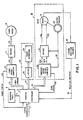
- the present invention is used with a printer system shown in Fig. 1.
- This printer system receives commands via a serial communications link 2 which are decoded by the printer controller 6 and used in conjunction with status set by an operator panel 4 connected to controller 6 by a panel cable 8.
- Controller 6 may be of the type shown in the European patent application No. 80105774.6, filed September 25, 1980, entitled “Printer Subsystem With Microprocessor Control” and published May 6, 1981 (Publication No. 27899).
- the controller commands are supplied by way of a cable 10 to a forms microcomputer 12 in the form of a single chip microcomputer which supplies open loop drive commutation signals to a power driver 14.
- the power driver provides drive voltage to a forms stepper motor 16.
- the command to move is given to forms microcomputer 12 by way of command lines on cable 10 from printer controller 6, and status is returned to the printer controller by way of the forms status lines 13.
- the print actuator system 19 attached to the print head carriage includes actuator latches 20 and print actuators 24 and does the actual print image formation of the images formed by printer controller 6.
- the dot pattern to be printed is transmitted from controller 6 to latches 20, and then to actuators 24.
- the dot placement for the characters printed is determined by printer controller 6, based on information from a linear position encoder system attached to the print head carriage system 38.
- Actuator carriage position is determined by a linear position encoder 44 which may include an optical detector attached to the carriage which is driven by the head motor system and a stationary optical grid attached to the printer frame, as is well known in the art.
- the carrier assembly is attached to the print head drive motor 36 by a timing belt and as the carrier moves, the attached optical detector moves across the grid and generates position emitter signals on a line 46 which are used by printer controller 6 to form characters.
- the actuator carriage print head motor drive system 38 includes a carriage drive microcomputer 28 and a power driver 32 attached to brush DC head motor 36 by way of cables 34a, 34b. Attached to the shaft of head motor 36 is a rotary optical encoder 40 with 810 cycles per revolution. This encoder is used by carriage drive microcomputer 28 to provide speed information. Instructions for controlling the print head motion are given to microcomputer 28 via command lines 26 and status is returned to printer controller 6 by means of status lines 50.
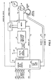
- the head drive system 38 is seen in more detail in Fig. 2.
- the carriage drive microcomputer 28 may be a single chip Intel 8049 microcomputer. As shown, microcomputer 28 is provided with a portion of read-only storage (ROS) 28a. Movement commands on line 26 are received and decoded by the carriage drive microcomputer. These commands are negative active run, go left (or plus go right), select negative active high speed (or positive active low speed), and reset error condition. The status reported to printer controller 6 by way of status lines are minus active head error and plus active carriage drive microcomputer busy.
- ROS read-only storage
- Actuator carriage motion is initiated by providing an error voltage to the head drive circuitry, this error voltage being developed by the microcomputer.
- the microcomputer outputs an 8-bit digital value to a digital to analog converter (DAC 29) such that a portion of a reference -voltage appearing at a terminal 41 is transmitted to a pulse width modulator 39 as the error voltage.
- the error voltage is used by pulse width modulation amplifier 39 to develop a chopped DC control signal with the plus duty cycle increasing as the error voltage increases.
- the duty cycle signal determines the percentage of time that the drive voltage is applied to motor 36 through the wires 34a, 34b. This pulse width modulated DC signal provides the mechanism to accomplish speed control in the system.
- the direction of application of drive voltage to motor 36 is determined by the controlling output - drive left from microcomputer 28 on line 51 to the power drive transistors 49. This permits bidirectional drive to motor 36 which allows controlled bidirectional (left to right and right to left) of the attached load 58 which is the actuator carriage or print head. Motor overcurrent is sensed and when activated disables the drive and notifies the carriage control microcomputer.
- Speed information to be used in controlling the actuator carriage velocity is obtained by monitoring the outputs of two symmetrical optical encoders that are phase shifted from one another by ninety degrees; encoder "A" 40a and encoder “B” 40b. These encoder signals are developed from the optical disk 40 monitored by the optical detector 41 attached to the motor housing.
- printer controller 6 communicates with carriage drive microcomputer 28 via command lines 26 (Fig. 2).
- the Reset command causes a reset of the error status line.
- a Diagnostic command from the printer controller 6 causes the carriage drive microcomputer 28 to perform a set of internal hardware verification diagnostics and to report an error status or satisfactory completion status. This ensures proper operation of the microcomputer and aids in printer error isolation.
- the motion commands received from the printer controller 6 are either drive at detent speed (a very low speed) in the direction commanded or run at either high or low speed in the direction selected. These two commands will be combined in further explanation of a "Run" command.
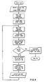
- Motion begins when a Run command is received by microcomputer 28 from the printer controller, as shown in the Command Decode flowchart in Fig. 3. Speed and direction information is read and stored. The drive direction line ("-Drive Left") is set to the desired motion direction. The speed select lines are then used to select the starting, running, and stopping table pointers in ROS 28a for the desired speed, and an initial value for the error voltage is set to DAC 29.
- microcomputer 28 waits until a change in the encoder signals from encoder 40 occurs as seen in the Start Sequence Flowchart in Fig. 4. Then timing is started and microcomputer 28 waits till the next transition occurs. Symmetry and quadrature variations in the encoder signals may make it necessary to measure from one edge transition to the next same transition (rising to rising or falling to falling) of only one encoder.
- the timer value is read and reset. The time required to move this encoder cycle is compared to a stored value in ROS 28a.
- This ROS time value represents the desired current motion velocity at this point in the acceleration (start) process.
- the ROS time value for each encoder change (or group or encoder changes) in stored in a sequential table to allow easy access. The pointer to the ROS value being used from this table changes depending upon the number of encoder transitions counted from zero velocity.
- the difference in the actual measured time and the desired encoder time from ROS 28a is measured and is used to generate a correction to the DAC error voltage. If the velocity is too large, the error voltage generation algorithm will decrease the DAC error voltage, and if the velocity is not enough, this algorithm will increase the DAC error voltage.
- the ROS table sequencing, time measurement, and error voltage correction cycle will continue until a table ROS value of 0 is reached. This indicates that starting is completed, the next ROS value in the table is the steady state run value for the speed selected. The ROS table selected and final velocity time value are different for each speed selected.
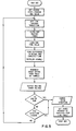
- the run sequence program maintains the desired speed.
- the encoder output signals are monitored and the DAC error output voltage is modified to ensure that sufficient drive is maintained to overcome friction and loading effects.
- the initial value set into DAC 29 when run motion is started is the steady state average error count as determined by an error averaging algorithm.
- each encoder change is timed as before.
- the measured time (velocity) value is compared with the expected time (desired velocity). The difference is used by the error voltage generation algorithm to decrease the DAC voltage if the speed is too large, or increase the DAC voltage if the speed is too slow.
- the microcomputer tests the input commands and if the run signal is no longer active or the direction command line has changed state, stopping begins. If no change is detected, constant velocity speed control continues.
- the motor drive direction (“-Drive Left") is changed and the stop sequence begins as shown in the flowchart of Fig. 6. Then the initial DAC reverse drive count is transmitted to the DAC. This induced large error voltage value (speed dependent) causes the motor to drive in the opposite direction. Then the table of ROS stopping values is accessed, as seen in Fig. 6. The time between encoder transitions (same edge to same edge as before) is measured and compared with the desired ROS time (speed) value. When the time between encoder changes becomes excessively long or the encoder sequence changes, then zero velocity has been achieved and the command input lines are sampled. Until zero velocity has been achieved, the difference in the measured and desired time values is used by the error voltage generation algorithm to increase or decrease the DAC errorvoltage and continue stopping. The ROS stopping table pointer changes depending on the number of encoder transitions counted since stopping began. Once stopping is completed, motion may then begin again in either direction desired.
- the errorvoltage generation algorithm takes the time error between the measured and desired encoder signals and determines the output DAC error voltage.
- the error voltage may be calculated using a formula or may be evaluated by using look- up tables, but the net results are the same.
- a basic principle behind either method is the concept of non-linear error signal scaling, which requires the microcomputer to change the time difference versus error voltage formula (relationship) depending on whether starting, running, or stopping is taking place.
- the encoders When first starting motion, the encoders come at a very slow rate. This means that when the time difference between actual and desired velocity is evaluated, thetimevalue may be large. However, a large resultant change in the DAC error voltage at that time is not desirable since fast acceleration is dependent on a large DAC error voltage. Therefore, the time value measured is divided down (or scaled) so that only a small portion of the time measures is used to change the DAC value, bit for bit (one data bit changes one DAC bit). As speed increases, the acceleration control on the DAC becomes more important to prevent overshoot of final velocity. Therefore, time differences measured at about half of final speed should have more effect in the DAC output.
- the scaling changes stop and the time differences translate almost bit for bit into DAC output value changes.
- the scaling changes again begin, but the weighting factors are different.
- the encoders are changing fast and the difference values are small. Scaling takes place here but the scaling magnitude is small compared to starting motion. Then as velocity decreases, the scaling decreases. This means that the difference values calculated are transmitted to the DAC, decreasing the error voltage drive as the motor slows down. Once low velocities are reached (as determined by measured encoder times) the scaling again increases. This final scaling increase is to insure that the large time difference values do not cause overshoot of zero velocity.
- FIG. 7 A typical velocity and the DAC output profile is shown in Fig. 7, illustrating the DAC error voltage stepping down to the run level, and showing the decreasing spacing in the encoder A and encoder B signals as the carriage approaches run speed. If a turnaround was desired instead of stopping, the stopping sequence scaling would be slightly different and a special turnaround scaling and ROS velocity time value table would be required.
- the error count (which is the DAC input) can be averaged over the run time. This average value is determined by an error averaging algorithm and can be used to adjust the nominal reference value for the next line to be printed. If bidirectional differences occur, it is possible to have different values for each direction and also different values for each operating speed.
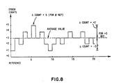
- Fig. 8 shows a typical averaging operation. For this example, the error count varies from 1 to 5 counts from the reference. If the reference is updated by the average error over this period (in this case 3 counts), then the maximum error is only plus or minus 2 counts.
Landscapes
- Engineering & Computer Science (AREA)
- Power Engineering (AREA)
- Character Spaces And Line Spaces In Printers (AREA)
- Control Of Electric Motors In General (AREA)
- Accessory Devices And Overall Control Thereof (AREA)
- Motor And Converter Starters (AREA)
Description
- This invention relates to printer control systems and relates more particularly print head to control systems for controlling the velocity of a print head used in multi-speed bidirectional printers.
- A multi-speed bidirectional printer is a device in which a print carriage containing a printing mechanism is driven past a medium on which printing is to take place, the carriage and printing mechanism being controllable to move at different speeds on different lines and being capable of printing in both directions. In printers of this type, it is necessary to accelerate the carriage in the margin area of the medium so that it is up to the required speed when it reaches the printing area, maintain the desired speed as the carriage traverses a line in the printing area; and then decelerate the carriage for stopping or stopping and turning around at the end of the printing line. In such a system, it is important for printer throughput purposes that the acceleration and deceleration be carried out as rapidly as possible and that the speed during printing be substantially constant.
- One factor which makes realization of these performance goals difficult to achieve over the life of a printer is that the printer system's dynamics often change from machine to machine and as a function of time as components wear and age. Hence, a control system which is capable of providing optimal control early in the life of a given printer may not be capable of such control later in the life of that printer or with another printer which is seemingly identical to that printer, but which has slightly different characteristics.
- An additional factor which makes it difficult to attain these goals is that even at the same speed, a printer may have different characteristics depending on which direction it is running, thus making it harder to develop a control algorithm for a common printing speed.
- The advantage of the present invention is to provide an improved print head velocity control means in which the velocity of the print head is maintained at a desired value.
- U.S. Patent 4,146,922, and 4,147,967 disclosed the use of microprocessors to control a print carrier. EP-A-31906 discloses an apparatus for dynamically monitoring the friction associated with an electromechanical system. However, neither of these patents address the problem solved by the present invention.
- European patent application n° 82107807.8 (EP-A-77455) with the same priority as the present application relates to a print head control system with controlled acceleration and deceleration and more particularly to control systems for multi-speed bidirectional printers such as the one of the present invention.
- In accordance with the present invention, a printer control system is provided in which an error count, which provides a digital measure of the difference between a desired velocity and the actual velocity, is updated for each line printed so as to maintain the error count at a minimum value for the next line to be printed.
- The object of the invention is to provide a device as defined in
claim 1. -
- FIG. 1 is a diagram of the overall printer control system;
- FIG. 2 is a diagram illustrating details of the printer carriage control system;
- FIGS. 3-6 are flow charts illustrating the sequence during start, run and stop operations;
- FIG. 7 is a graph illustrating different outputs during start, run and stop operations; and
- FIG. 8 is a graph illustrating averaging the error counts in the control system.
- The present invention is used with a printer system shown in Fig. 1. This printer system receives commands via a
serial communications link 2 which are decoded by the printer controller 6 and used in conjunction with status set by anoperator panel 4 connected to controller 6 by apanel cable 8. Controller 6 may be of the type shown in the European patent application No. 80105774.6, filed September 25, 1980, entitled "Printer Subsystem With Microprocessor Control" and published May 6, 1981 (Publication No. 27899). The controller commands are supplied by way of acable 10 to aforms microcomputer 12 in the form of a single chip microcomputer which supplies open loop drive commutation signals to apower driver 14. The power driver provides drive voltage to aforms stepper motor 16. The command to move is given toforms microcomputer 12 by way of command lines oncable 10 from printer controller 6, and status is returned to the printer controller by way of theforms status lines 13. - The print actuator system 19 attached to the print head carriage includes
actuator latches 20 andprint actuators 24 and does the actual print image formation of the images formed by printer controller 6. The dot pattern to be printed is transmitted from controller 6 tolatches 20, and then toactuators 24. The dot placement for the characters printed is determined by printer controller 6, based on information from a linear position encoder system attached to the printhead carriage system 38. - Actuator carriage position is determined by a
linear position encoder 44 which may include an optical detector attached to the carriage which is driven by the head motor system and a stationary optical grid attached to the printer frame, as is well known in the art. The carrier assembly is attached to the printhead drive motor 36 by a timing belt and as the carrier moves, the attached optical detector moves across the grid and generates position emitter signals on aline 46 which are used by printer controller 6 to form characters. - The actuator carriage print head
motor drive system 38 includes acarriage drive microcomputer 28 and apower driver 32 attached to brushDC head motor 36 by way ofcables head motor 36 is a rotaryoptical encoder 40 with 810 cycles per revolution. This encoder is used bycarriage drive microcomputer 28 to provide speed information. Instructions for controlling the print head motion are given tomicrocomputer 28 viacommand lines 26 and status is returned to printer controller 6 by means of status lines 50. - The
head drive system 38 is seen in more detail in Fig. 2. Thecarriage drive microcomputer 28 may be a single chip Intel 8049 microcomputer. As shown,microcomputer 28 is provided with a portion of read-only storage (ROS) 28a. Movement commands online 26 are received and decoded by the carriage drive microcomputer. These commands are negative active run, go left (or plus go right), select negative active high speed (or positive active low speed), and reset error condition. The status reported to printer controller 6 by way of status lines are minus active head error and plus active carriage drive microcomputer busy. - Actuator carriage motion is initiated by providing an error voltage to the head drive circuitry, this error voltage being developed by the microcomputer. The microcomputer outputs an 8-bit digital value to a digital to analog converter (DAC 29) such that a portion of a reference -voltage appearing at a
terminal 41 is transmitted to apulse width modulator 39 as the error voltage. The error voltage is used by pulsewidth modulation amplifier 39 to develop a chopped DC control signal with the plus duty cycle increasing as the error voltage increases. The duty cycle signal determines the percentage of time that the drive voltage is applied tomotor 36 through thewires motor 36 is determined by the controlling output - drive left frommicrocomputer 28 online 51 to thepower drive transistors 49. This permits bidirectional drive tomotor 36 which allows controlled bidirectional (left to right and right to left) of the attachedload 58 which is the actuator carriage or print head. Motor overcurrent is sensed and when activated disables the drive and notifies the carriage control microcomputer. - Speed information to be used in controlling the actuator carriage velocity is obtained by monitoring the outputs of two symmetrical optical encoders that are phase shifted from one another by ninety degrees; encoder "A" 40a and encoder "B" 40b. These encoder signals are developed from the
optical disk 40 monitored by theoptical detector 41 attached to the motor housing. - As mentioned above, printer controller 6 communicates with
carriage drive microcomputer 28 via command lines 26 (Fig. 2). The Reset command causes a reset of the error status line. A Diagnostic command from the printer controller 6 causes thecarriage drive microcomputer 28 to perform a set of internal hardware verification diagnostics and to report an error status or satisfactory completion status. This ensures proper operation of the microcomputer and aids in printer error isolation. The motion commands received from the printer controller 6 are either drive at detent speed (a very low speed) in the direction commanded or run at either high or low speed in the direction selected. These two commands will be combined in further explanation of a "Run" command. - Motion begins when a Run command is received by
microcomputer 28 from the printer controller, as shown in the Command Decode flowchart in Fig. 3. Speed and direction information is read and stored. The drive direction line ("-Drive Left") is set to the desired motion direction. The speed select lines are then used to select the starting, running, and stopping table pointers inROS 28a for the desired speed, and an initial value for the error voltage is set toDAC 29. - Once the DAC voltage has been applied,
microcomputer 28 waits until a change in the encoder signals fromencoder 40 occurs as seen in the Start Sequence Flowchart in Fig. 4. Then timing is started andmicrocomputer 28 waits till the next transition occurs. Symmetry and quadrature variations in the encoder signals may make it necessary to measure from one edge transition to the next same transition (rising to rising or falling to falling) of only one encoder. Each time the desired transition is reached, the timer value is read and reset. The time required to move this encoder cycle is compared to a stored value inROS 28a. This ROS time value represents the desired current motion velocity at this point in the acceleration (start) process. The ROS time value for each encoder change (or group or encoder changes) in stored in a sequential table to allow easy access. The pointer to the ROS value being used from this table changes depending upon the number of encoder transitions counted from zero velocity. - The difference in the actual measured time and the desired encoder time from
ROS 28a is measured and is used to generate a correction to the DAC error voltage. If the velocity is too large, the error voltage generation algorithm will decrease the DAC error voltage, and if the velocity is not enough, this algorithm will increase the DAC error voltage. The ROS table sequencing, time measurement, and error voltage correction cycle will continue until a table ROS value of 0 is reached. This indicates that starting is completed, the next ROS value in the table is the steady state run value for the speed selected. The ROS table selected and final velocity time value are different for each speed selected. - When the final desired speed has been reached, the run sequence program, as shown in the flowchart of Fig. 5, maintains the desired speed. The encoder output signals are monitored and the DAC error output voltage is modified to ensure that sufficient drive is maintained to overcome friction and loading effects. The initial value set into
DAC 29 when run motion is started is the steady state average error count as determined by an error averaging algorithm. - While running, each encoder change is timed as before. The measured time (velocity) value is compared with the expected time (desired velocity). The difference is used by the error voltage generation algorithm to decrease the DAC voltage if the speed is too large, or increase the DAC voltage if the speed is too slow. The microcomputer tests the input commands and if the run signal is no longer active or the direction command line has changed state, stopping begins. If no change is detected, constant velocity speed control continues.
- The motor drive direction ("-Drive Left") is changed and the stop sequence begins as shown in the flowchart of Fig. 6. Then the initial DAC reverse drive count is transmitted to the DAC. This induced large error voltage value (speed dependent) causes the motor to drive in the opposite direction. Then the table of ROS stopping values is accessed, as seen in Fig. 6. The time between encoder transitions (same edge to same edge as before) is measured and compared with the desired ROS time (speed) value. When the time between encoder changes becomes excessively long or the encoder sequence changes, then zero velocity has been achieved and the command input lines are sampled. Until zero velocity has been achieved, the difference in the measured and desired time values is used by the error voltage generation algorithm to increase or decrease the DAC errorvoltage and continue stopping. The ROS stopping table pointer changes depending on the number of encoder transitions counted since stopping began. Once stopping is completed, motion may then begin again in either direction desired.
- The errorvoltage generation algorithm takes the time error between the measured and desired encoder signals and determines the output DAC error voltage. The error voltage may be calculated using a formula or may be evaluated by using look- up tables, but the net results are the same. A basic principle behind either method is the concept of non-linear error signal scaling, which requires the microcomputer to change the time difference versus error voltage formula (relationship) depending on whether starting, running, or stopping is taking place.
- When first starting motion, the encoders come at a very slow rate. This means that when the time difference between actual and desired velocity is evaluated, thetimevalue may be large. However, a large resultant change in the DAC error voltage at that time is not desirable since fast acceleration is dependent on a large DAC error voltage. Therefore, the time value measured is divided down (or scaled) so that only a small portion of the time measures is used to change the DAC value, bit for bit (one data bit changes one DAC bit). As speed increases, the acceleration control on the DAC becomes more important to prevent overshoot of final velocity. Therefore, time differences measured at about half of final speed should have more effect in the DAC output. This is accomplished by dividing down (scaling) the time values less, such that a time value at high speed will cause more of a DAC value change than at low speed. Finally, when approaching final velocity, the timer difference between the measured and desired velocities is not scaled at all or only slightly. This increases the gain of the system providing better speed regulation. For starting, the scale factor changes are dependent on the velocity as reflected in the measured time or as the number of encoder transitions since starting began.
- Once final velocity is reached, the scaling changes stop and the time differences translate almost bit for bit into DAC output value changes. When stopping, the scaling changes again begin, but the weighting factors are different. When beginning to stop, the encoders are changing fast and the difference values are small. Scaling takes place here but the scaling magnitude is small compared to starting motion. Then as velocity decreases, the scaling decreases. This means that the difference values calculated are transmitted to the DAC, decreasing the error voltage drive as the motor slows down. Once low velocities are reached (as determined by measured encoder times) the scaling again increases. This final scaling increase is to insure that the large time difference values do not cause overshoot of zero velocity.
- A typical velocity and the DAC output profile is shown in Fig. 7, illustrating the DAC error voltage stepping down to the run level, and showing the decreasing spacing in the encoder A and encoder B signals as the carriage approaches run speed. If a turnaround was desired instead of stopping, the stopping sequence scaling would be slightly different and a special turnaround scaling and ROS velocity time value table would be required.
- Since the speed error at full speed is due to friction (once overshoot and undershoot have settled out), the error count (which is the DAC input) can be averaged over the run time. This average value is determined by an error averaging algorithm and can be used to adjust the nominal reference value for the next line to be printed. If bidirectional differences occur, it is possible to have different values for each direction and also different values for each operating speed. Fig. 8 shows a typical averaging operation. For this example, the error count varies from 1 to 5 counts from the reference. If the reference is updated by the average error over this period (in this
case 3 counts), then the maximum error is only plus or minus 2 counts.
Claims (4)
Applications Claiming Priority (2)
| Application Number | Priority Date | Filing Date | Title |
|---|---|---|---|
| US06/312,057 US4459675A (en) | 1981-10-16 | 1981-10-16 | Printer control system with error count averaging |
| US312057 | 1981-10-16 |
Publications (2)
| Publication Number | Publication Date |
|---|---|
| EP0078387A1 EP0078387A1 (en) | 1983-05-11 |
| EP0078387B1 true EP0078387B1 (en) | 1987-04-22 |
Family
ID=23209691
Family Applications (1)
| Application Number | Title | Priority Date | Filing Date |
|---|---|---|---|
| EP82108520A Expired EP0078387B1 (en) | 1981-10-16 | 1982-09-16 | Print head velocity control system with error count averaging |
Country Status (8)
| Country | Link |
|---|---|
| US (1) | US4459675A (en) |
| EP (1) | EP0078387B1 (en) |
| JP (1) | JPS5872489A (en) |
| AU (1) | AU554680B2 (en) |
| BR (1) | BR8205807A (en) |
| CA (1) | CA1191386A (en) |
| DE (1) | DE3276145D1 (en) |
| ES (1) | ES516529A0 (en) |
Families Citing this family (28)
| Publication number | Priority date | Publication date | Assignee | Title |
|---|---|---|---|---|
| GB2110852B (en) * | 1981-10-19 | 1985-02-13 | Canon Kk | Printer |
| JPS61500704A (en) * | 1983-12-15 | 1986-04-10 | バクスタ−、トラベノ−ル、ラボラトリ−ズ、インコ−ポレイテッド | motor control system |
| US4646635A (en) * | 1984-10-04 | 1987-03-03 | Pitney Bowes Inc. | Microprocessor controlled D.C. motor for controlling print value selection means |
| US4656403A (en) * | 1985-03-21 | 1987-04-07 | Siemens Aktiengensellschaft | Digital speed control circuit for a DC motor |
| US4775945A (en) * | 1985-12-11 | 1988-10-04 | International Business Machines Corporation | Print head motor control system with automatic drive parameter calculations |
| US4777609A (en) * | 1985-12-11 | 1988-10-11 | International Business Machines Corporation | Print head motor control system having steady state velocity compensation |
| JPH0681536B2 (en) * | 1987-08-25 | 1994-10-12 | 松下電器産業株式会社 | Compensator |
| JPH0681533B2 (en) * | 1986-03-11 | 1994-10-12 | 松下電器産業株式会社 | Motor speed controller |
| JPH0681534B2 (en) * | 1986-03-11 | 1994-10-12 | 松下電器産業株式会社 | Motor speed controller |
| JPH0681535B2 (en) * | 1986-03-11 | 1994-10-12 | 松下電器産業株式会社 | Motor speed controller |
| US4854756A (en) * | 1987-08-03 | 1989-08-08 | Printronix, Inc. | Adaptive print hammer timing system |
| JPH0773431B2 (en) * | 1987-08-25 | 1995-08-02 | 松下電器産業株式会社 | Compensator |
| JPH01154666A (en) * | 1987-12-11 | 1989-06-16 | Nitsuko Corp | Pos system |
| EP0352397B1 (en) * | 1988-07-26 | 1993-01-07 | MANNESMANN Aktiengesellschaft | Speed control device for pulse width-modulated electric motors, especially for direct current motors |
| JP2547079B2 (en) * | 1988-08-30 | 1996-10-23 | アルプス電気株式会社 | Printer |
| JPH0798414B2 (en) * | 1989-07-18 | 1995-10-25 | キヤノン株式会社 | Recording device |
| US5116150A (en) * | 1991-01-09 | 1992-05-26 | Apple Computer, Inc. | Apparatus and method for mapping and aligning digital images onto printed media |
| US5392706A (en) * | 1992-07-30 | 1995-02-28 | Markem Corporation | Pad transfer printing method |
| US6819448B2 (en) * | 1998-09-28 | 2004-11-16 | Hewlett-Packard Development Company, L.P. | Printer with print mode masking periodic carriage vibration |
| US6428224B1 (en) | 1999-12-21 | 2002-08-06 | Lexmark International, Inc. | Error mapping technique for a printer |
| US6583803B2 (en) | 2001-01-29 | 2003-06-24 | Zih Corporation | Thermal printer with sacrificial member |
| US6956672B1 (en) | 2001-04-05 | 2005-10-18 | Lexmark International, Inc. | Method for mixing inks for high fidelity color printing |
| US6554395B2 (en) * | 2001-06-08 | 2003-04-29 | Texas Instruments Incorporated | Print head servo and velocity controller with non-linear compensation |
| US7205738B2 (en) * | 2004-03-24 | 2007-04-17 | Lexmark International, Inc. | Method and apparatus for time-based dc motor commutation |
| US20090152351A1 (en) * | 2007-12-14 | 2009-06-18 | Michael Nordlund | Detecting An Encoder Material Reading Error |
| US9211741B2 (en) | 2012-07-17 | 2015-12-15 | Hewlett-Packard Development Company, L.P. | Position encoder systems |
| US9523947B2 (en) | 2012-09-26 | 2016-12-20 | Lexmark International, Inc. | Time-based commutation method and system for controlling a fuser assembly |
| US8836747B2 (en) | 2012-10-02 | 2014-09-16 | Lexmark International, Inc. | Motor control system and method for a laser scanning unit of an imaging apparatus |
Citations (2)
| Publication number | Priority date | Publication date | Assignee | Title |
|---|---|---|---|---|
| EP0031906A2 (en) * | 1979-12-31 | 1981-07-15 | International Business Machines Corporation | Method and apparatus for determining friction associated with an electric motor |
| EP0077455A1 (en) * | 1981-10-16 | 1983-04-27 | International Business Machines Corporation | Print head control system with controlled acceleration and deceleration |
Family Cites Families (7)
| Publication number | Priority date | Publication date | Assignee | Title |
|---|---|---|---|---|
| US4021650A (en) * | 1975-11-19 | 1977-05-03 | Xerox Corporation | Velocity command signal generating apparatus |
| JPS5272077A (en) * | 1975-12-05 | 1977-06-16 | Hitachi Ltd | Positioning system |
| US4146922A (en) * | 1977-08-29 | 1979-03-27 | Ncr Corporation | Constant velocity driving means |
| US4147967A (en) * | 1977-11-10 | 1979-04-03 | Ncr Corporation | Apparatus and method for controlling the velocity of a moveable member |
| EP0009291B1 (en) * | 1978-09-20 | 1982-10-27 | Philips Norden AB | A device for indicating the position of a printer carriage |
| US4270868A (en) * | 1978-10-24 | 1981-06-02 | International Business Machines Corporation | Digital pulse-width modulated printer escapement control system |
| US4353020A (en) * | 1978-11-01 | 1982-10-05 | Plessey Peripheral Systems | Impact printer programmed servo system |
-
1981
- 1981-10-16 US US06/312,057 patent/US4459675A/en not_active Expired - Fee Related
-
1982
- 1982-09-16 EP EP82108520A patent/EP0078387B1/en not_active Expired
- 1982-09-16 DE DE8282108520T patent/DE3276145D1/en not_active Expired
- 1982-09-21 CA CA000411850A patent/CA1191386A/en not_active Expired
- 1982-10-04 AU AU88990/82A patent/AU554680B2/en not_active Ceased
- 1982-10-04 BR BR8205807A patent/BR8205807A/en not_active IP Right Cessation
- 1982-10-08 JP JP57176507A patent/JPS5872489A/en active Granted
- 1982-10-15 ES ES516529A patent/ES516529A0/en active Granted
Patent Citations (2)
| Publication number | Priority date | Publication date | Assignee | Title |
|---|---|---|---|---|
| EP0031906A2 (en) * | 1979-12-31 | 1981-07-15 | International Business Machines Corporation | Method and apparatus for determining friction associated with an electric motor |
| EP0077455A1 (en) * | 1981-10-16 | 1983-04-27 | International Business Machines Corporation | Print head control system with controlled acceleration and deceleration |
Also Published As
| Publication number | Publication date |
|---|---|
| EP0078387A1 (en) | 1983-05-11 |
| CA1191386A (en) | 1985-08-06 |
| DE3276145D1 (en) | 1987-05-27 |
| AU8899082A (en) | 1983-04-21 |
| JPH0134158B2 (en) | 1989-07-18 |
| BR8205807A (en) | 1983-09-06 |
| JPS5872489A (en) | 1983-04-30 |
| ES8307602A1 (en) | 1983-08-01 |
| US4459675A (en) | 1984-07-10 |
| ES516529A0 (en) | 1983-08-01 |
| AU554680B2 (en) | 1986-08-28 |
Similar Documents
| Publication | Publication Date | Title |
|---|---|---|
| US4459675A (en) | Printer control system with error count averaging | |
| US4463435A (en) | Printer control system with controlled acceleration and deceleration | |
| EP0077446B1 (en) | Print head velocity control system using analog and digital feedback | |
| US4777609A (en) | Print head motor control system having steady state velocity compensation | |
| EP0077465B1 (en) | Print head motor control system with stop distance compensation | |
| US4775945A (en) | Print head motor control system with automatic drive parameter calculations | |
| US4851755A (en) | Low power stepper motor drive system and method | |
| US6838855B2 (en) | Method and apparatus for controlling motor | |
| US4477757A (en) | Phase commutator for closed loop control of a stepping motor | |
| US4507592A (en) | Microprocessor controlled tape capstan | |
| US5774626A (en) | Programmable dual-phase digital motor control with sliding proportionality | |
| US5287233A (en) | Digital data storage magnetic tape system comprising a single chip processor to control a tape tension servo, and a head drum servo | |
| EP0099977B1 (en) | Digital servo system for motor control | |
| JP2004086610A (en) | Motor control method and control device | |
| JPS6156713B2 (en) | ||
| JPS6311684B2 (en) | ||
| JPH03132380A (en) | recording device | |
| JPS6347180A (en) | Controlling method for spacing mechanism | |
| JPH03198699A (en) | Drive controlling method for carriage motor |
Legal Events
| Date | Code | Title | Description |
|---|---|---|---|
| PUAI | Public reference made under article 153(3) epc to a published international application that has entered the european phase |
Free format text: ORIGINAL CODE: 0009012 |
|
| AK | Designated contracting states |
Designated state(s): BE CH DE FR GB IT LI NL |
|
| 17P | Request for examination filed |
Effective date: 19830823 |
|
| GRAA | (expected) grant |
Free format text: ORIGINAL CODE: 0009210 |
|
| AK | Designated contracting states |
Kind code of ref document: B1 Designated state(s): BE CH DE FR GB IT LI NL |
|
| PG25 | Lapsed in a contracting state [announced via postgrant information from national office to epo] |
Ref country code: BE Effective date: 19870422 |
|
| REF | Corresponds to: |
Ref document number: 3276145 Country of ref document: DE Date of ref document: 19870527 |
|
| ITF | It: translation for a ep patent filed | ||
| ET | Fr: translation filed | ||
| PG25 | Lapsed in a contracting state [announced via postgrant information from national office to epo] |
Ref country code: LI Effective date: 19870930 Ref country code: CH Effective date: 19870930 |
|
| PLBE | No opposition filed within time limit |
Free format text: ORIGINAL CODE: 0009261 |
|
| STAA | Information on the status of an ep patent application or granted ep patent |
Free format text: STATUS: NO OPPOSITION FILED WITHIN TIME LIMIT |
|
| 26N | No opposition filed | ||
| REG | Reference to a national code |
Ref country code: CH Ref legal event code: PL |
|
| ITTA | It: last paid annual fee | ||
| PGFP | Annual fee paid to national office [announced via postgrant information from national office to epo] |
Ref country code: GB Payment date: 19900803 Year of fee payment: 9 |
|
| PGFP | Annual fee paid to national office [announced via postgrant information from national office to epo] |
Ref country code: FR Payment date: 19900828 Year of fee payment: 9 |
|
| PGFP | Annual fee paid to national office [announced via postgrant information from national office to epo] |
Ref country code: NL Payment date: 19900930 Year of fee payment: 9 |
|
| PGFP | Annual fee paid to national office [announced via postgrant information from national office to epo] |
Ref country code: DE Payment date: 19901004 Year of fee payment: 9 |
|
| PG25 | Lapsed in a contracting state [announced via postgrant information from national office to epo] |
Ref country code: GB Effective date: 19910916 |
|
| PG25 | Lapsed in a contracting state [announced via postgrant information from national office to epo] |
Ref country code: NL Effective date: 19920401 |
|
| GBPC | Gb: european patent ceased through non-payment of renewal fee | ||
| NLV4 | Nl: lapsed or anulled due to non-payment of the annual fee | ||
| PG25 | Lapsed in a contracting state [announced via postgrant information from national office to epo] |
Ref country code: FR Effective date: 19920529 |
|
| PG25 | Lapsed in a contracting state [announced via postgrant information from national office to epo] |
Ref country code: DE Effective date: 19920602 |
|
| REG | Reference to a national code |
Ref country code: FR Ref legal event code: ST |