EP0077566A1 - Disc cassette (disc cartridge) - Google Patents
Disc cassette (disc cartridge) Download PDFInfo
- Publication number
- EP0077566A1 EP0077566A1 EP82109641A EP82109641A EP0077566A1 EP 0077566 A1 EP0077566 A1 EP 0077566A1 EP 82109641 A EP82109641 A EP 82109641A EP 82109641 A EP82109641 A EP 82109641A EP 0077566 A1 EP0077566 A1 EP 0077566A1
- Authority
- EP
- European Patent Office
- Prior art keywords
- disc
- cassette
- shutter
- disc cassette
- belt
- Prior art date
- Legal status (The legal status is an assumption and is not a legal conclusion. Google has not performed a legal analysis and makes no representation as to the accuracy of the status listed.)
- Granted
Links
- 210000002105 tongue Anatomy 0.000 description 5
- 239000000428 dust Substances 0.000 description 4
- 230000008021 deposition Effects 0.000 description 1
- 238000010438 heat treatment Methods 0.000 description 1
- 230000002265 prevention Effects 0.000 description 1
- 239000012260 resinous material Substances 0.000 description 1
Images

Classifications
-
- G—PHYSICS
- G11—INFORMATION STORAGE
- G11B—INFORMATION STORAGE BASED ON RELATIVE MOVEMENT BETWEEN RECORD CARRIER AND TRANSDUCER
- G11B23/00—Record carriers not specific to the method of recording or reproducing; Accessories, e.g. containers, specially adapted for co-operation with the recording or reproducing apparatus ; Intermediate mediums; Apparatus or processes specially adapted for their manufacture
- G11B23/02—Containers; Storing means both adapted to cooperate with the recording or reproducing means
- G11B23/03—Containers for flat record carriers
- G11B23/0301—Details
- G11B23/0308—Shutters
-
- G—PHYSICS
- G11—INFORMATION STORAGE
- G11B—INFORMATION STORAGE BASED ON RELATIVE MOVEMENT BETWEEN RECORD CARRIER AND TRANSDUCER
- G11B23/00—Record carriers not specific to the method of recording or reproducing; Accessories, e.g. containers, specially adapted for co-operation with the recording or reproducing apparatus ; Intermediate mediums; Apparatus or processes specially adapted for their manufacture
- G11B23/02—Containers; Storing means both adapted to cooperate with the recording or reproducing means
- G11B23/03—Containers for flat record carriers
- G11B23/033—Containers for flat record carriers for flexible discs
Definitions
- This invention relates to a disc cassette (disc cartridge) containing a flexible magnetic disc or other information recording disc, and more particularly it deals with a shutter opening and closing system for use with this type of disc cassette (disc cartridge).
- a flexible magnetic disc of the prior art has usually been contained in a case formed with an opening, such as a head window, or a center opening. Dust or foreign matter has tended to enter the case through the opening and be readily deposited on the magnetic disc. When the cassette is held at the opening by the fingers, the finger prints have tended to be formed on the surface of the magnetic disc. Deposition of dust or finger prints on the surface of the magnetic disc tends to cause a dropout to occur in signals reproduced from the magnetic disc. Thus it has hitherto been necessary to handle the case with meticulous care.
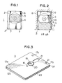
- FIG. 1 schematically shows a disc cassette of the prior art provided with a shutter.
- the disc cassette 1 includes a case 3 containing a flexible magnetic disc 2.
- the case 3 has arranged on its surface a shutter 4 adapted to move in sliding movement along guides 7.
- a spring 6 is mounted between the case 3 and the shutter 4 to normally keep the shutter 4 in a closed position by the biasing force of the spring 6.
- a projection 5 affixed to the shutter 4 abuts against a lever 9 attached to the apparatus 8, so that the spring 6 is expanded to bring the shutter 4 to an open position.
- the flexible magnetic disc 2 is exposed to view through a head window 10 formed in the case 3.
- the disc cassette 1 When it is desired to remove the disc cassette 1 from the apparatus 8, the disc cassette 1 is moved in the direction of an arrow B in Fig. 2 to contract the spring 6, so that the shutter is gradually brought to a closed position.
- This invention has as its object the provision of a disc cassette (disc cartridge) provided with a system for opening and closing a shutter for a head window of a case operative to open the shutter only when the disc cassette is mounted on a magnetic recording and reproducing apparatus and to automatically close the shutter smoothly as the disc cassette is removed from the apparatus.
- the magnetic disc uses a circular guide and the shutter moves in rotary movement along the single guide while being positively held by the guide.
- the shutter has secured thereto a spring in a position remote from the guide, to enable the shutter to be opened with a force of low magnitude and closed smoothly.
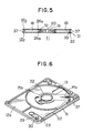
- the disc cassette according to the invention is shown in a perspective view in Fig. 3, in exploded perspective views in Figs. 4a, 4b and 4c and in a sectional view in Fig. 5.
- the disc cassette 11 comprising one embodiment comprises a half case 12a and a half case 12b rigidly formed of a synthetic resinous material and connected together in face-to-face relation to constitute a housing for containing a disc 18 therein.
- the half case 12a is formed with a head window 13, an opening 15a, an indexing window 16, positioning apertutes 17a and 17b and a cutout 21 and has a shutter 14a mounted thereon.
- the disc 18 has formed in the central portion thereof with a hub 19 formed with a hole 20.
- An indexing hole 51 is arranged on the disc 18.
- the half case 12b is formed with an opening 15b, positioning apertures 17a and 17b and a cutout 21.
- the half case 12b is formed, as is the case with the half case 12a, with a head window 13 and an indexing window 16.
- the half case 12b has a shutter 14b mounted thereon, the shutter 14b being composed of an annular portion 26a and a plate-like portion 26b, the annular portion 26a being fitted on a cylindrical guide 32 located around the opening 15b and the plate-like portion 26b being located in a position in which it is able to cover the head window 13.
- the annular portion 26a is fastened to the cylindrical guide 32 at a projection 34 formed at the cylindrical guide 32, the projection 34 being provided by heating and deforming a portion of the cylindrical guide 32.
- the shutter 14b is capable of rotating with respect to the cylindrical guide 32. Rotation of the shutter 14b causes the plate-like portion 26b to move, thereby exposing the head window 13 to view.
- the annular portion 26a is formed with a cutout 36 in one portion thereof.
- the indexing window 16 is covered with a portion of the annular portion 26a when the plate-like portion 26b of the shutter 14b is in the position in which it covers the head window 13.
- the cutput 36 is brought into index with the indexing window 16.
- the half cases 12a and 12b are formed with ribs 28a and 28b respectively which are brought into contact with each other when the half cases 12a and 12b are connected to each other.
- a vertical projection 27 is formed at each of four corners of the half case 12b which is adapted to be received in a recess, not shown, formed at each of four corners of the half case 12a. After being received in the recesses, the projections 27 are bonded to the half case 12a as by supersonic melt adhesion to connect the half cases 12a and 12b together.
- the half cases 12a and 12b are each formed with ribs 31 at opposite sides to provide the disc cassette 11 with guide channels 37.
- a rod-like guide 35 is formed in parallel with one of the ribs 31 to define there between a groove 25 which is extended in arcuate form to reach a point on a side above the head window 13.
- a resilient movable belt 22 of plate form Arranged in the groove 25 is a resilient movable belt 22 of plate form which moves in sliding movement therein.
- the half case 12a is also formed with a groove 25 in a position corresponding to that of the groove 25 of the half case 12b.
- the belt 22 is formed with a projection 23 at one end which is located in one of the guide channels 37, and a cutout 24 and a projection 33 at the other end.
- the cutout 24 has the plate-like portion 26b of the shutter 14b fitted therein.
- the movable belt 22 has fastened thereto one end of a torsion spring 29 secured at the other end to a projection 30 on the half case 12b.
- the torsion spring 29 is normally expanded to cause the belt 22 to move in sliding movement to make the shutters 14a and 14b to close the head windows 13. As a force is exerted on the projection 23, the torsion spring 29 is contracted as shown in Fig. 6, to thereby rotate the shutters 14a and 14b to open the head windows 13.
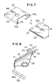
- Fig. 7 shows the essential portions of the disc cassette 11 and a cassette drive apparatus on which the disc cassette 11 is mounted.
- Cassette receiving means 41 of the apparatus including a case-like member formed with tongues 42a and 42b, guides 43 and 43, a window 44, and a hole 45.
- the disc cassette 11 is moved in the direction of an arrow A along the guides 43 and 43 to be inserted in the cassette receiving means 41.
- the tongues 42a and 42b are each in the form of a letter L and move in sliding movement along one of the channels 37 of the disc cassette 11.
- the tongue 42a abuts against the projection 23 of the disc cassette 11 to cause the latter to move in sliding movement. That is, a force is exerted by the tongue 42a on the projection 23.
- the torsion spring 29 is contracted and the shutters 14a and 14b are opened.
- the force exerted on the • projection 23 by the tongue 42a is released, to expand the torsion spring 29 and open the shutters 14a and 14b.
- the hub 19 is rotated by a shaft, not shown, extending through the hole 45, so that signals recorded in the disc 18 are reproduced through the window 44.
- Fig. 8 shows means for fastening the torsion spring 29 to the movable belt 22.
- the spring 29 its forward end portion 48 bent in the form of a letter U which is received in an opening 47 formed in a projection 46 of the movable belt 22 in locking relation.
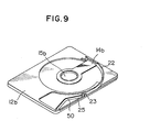
- Fig. 9 shows another embodiment of the disc cassette in conformity with the invention.
- the torsion spring 29 is replaced by a plate spring 50 which is expanded and contracted to open and close the shutter 14b.
- the shutters 14a and 14b of the disc cassette 11 rotate about one cylindrical guide 32, so that the shutters 14a and 14b can move smoothly.
- the movable belt 22 secured at one end to the torsion spring 29 is locked at the other end to a forward end of the plate-like portion 26b of the shutters 14a and 14b, so that the spring 29 is located remote from the cylindrical guide 32.
- This enables the shutters 14a and 14b to be positively closed even if the frictional dragging of the annular portion 26a of the shutters 14a and 14b on the cylindrical guide 32 is great and the spring 29 is low in resilience.
- the movable belt 22 and the projection 23 scarecely extends outwardly of the cassette 11, thereby preventing the shutters 14a and 14b being inadvertently opened.
- the shutter can be positively opened and closed.
- the shutter can be automatically opened as the disc cassette is mounted on a cassette drive apparatus and automatically closed as the former is removed from the latter.
- the chances of the shutter being inadvertently opened are very slim, and the disc cassette has the shutter closed at all times when it is not mounted in the cassette drive apparatus. This is conductive to prevention of dust or foreign matter from entering the cassette and of the fingers being mistakenly touching the surface of the disc.
Abstract
Description
- This invention relates to a disc cassette (disc cartridge) containing a flexible magnetic disc or other information recording disc, and more particularly it deals with a shutter opening and closing system for use with this type of disc cassette (disc cartridge).
-
- Fig. 1 is a front view of a disc cassette of the prior art;
- Fig. 2 is a sectional view of the disc cassette shown in Fig. 1, showing the disc cassette being mounted in a cassette drive apparatus;
- Fig. 3 is a perspective view of the disc cassette comprising one embodiment of the invention;
- Figs. 4a, 4b and 4c are exploded perspective views of the disc cassette according to the invention;
- Fig. 5 is a sectional view of the disc cassette according to the invention;
- Fig. 6 is an exploded perspective view of the disc cassette according to the invention;
- Fig. 7 is a perspective view of a cassette drive apparatus and a disc cassette;
- Fig. 8 is a perspective view of the essential portions of the disc cassette according to the invention; and
- Fig. 9 is a perspective view of the essential portions of another embodiment of the disc cassette in conformity with the invention.
- A flexible magnetic disc of the prior art has usually been contained in a case formed with an opening, such as a head window, or a center opening. Dust or foreign matter has tended to enter the case through the opening and be readily deposited on the magnetic disc. When the cassette is held at the opening by the fingers, the finger prints have tended to be formed on the surface of the magnetic disc. Deposition of dust or finger prints on the surface of the magnetic disc tends to cause a dropout to occur in signals reproduced from the magnetic disc. Thus it has hitherto been necessary to handle the case with meticulous care.
- To obviate this disadvantage of the prior art, proposals have been made to provide the case of a disc cassette with a shutter to keep dust and foreign matter from entering the case. Fig. 1 schematically shows a disc cassette of the prior art provided with a shutter. The
disc cassette 1 includes acase 3 containing a flexiblemagnetic disc 2. Thecase 3 has arranged on its surface ashutter 4 adapted to move in sliding movement alongguides 7. Aspring 6 is mounted between thecase 3 and theshutter 4 to normally keep theshutter 4 in a closed position by the biasing force of thespring 6. When thedisc cassette 1 is mounted on a magnetic recording and reproducing apparatus 8 in the direction of an arrow A in Fig. 2, a projection 5 affixed to theshutter 4 abuts against a lever 9 attached to the apparatus 8, so that thespring 6 is expanded to bring theshutter 4 to an open position. Thus the flexiblemagnetic disc 2 is exposed to view through ahead window 10 formed in thecase 3. - When it is desired to remove the
disc cassette 1 from the apparatus 8, thedisc cassette 1 is moved in the direction of an arrow B in Fig. 2 to contract thespring 6, so that the shutter is gradually brought to a closed position. - Some disadvantages are associated with this type of cassette disc provided with a shutter. In this type of disc cassette, the
shutter 4 should move along the twoguides 7 and thespring 6 is only located on one side of theshutter 4. This tends to tilt theshutter 4. Tilting of theshutter 4 increases the frictional dragging of theshutter 4 on theguides shutter 4 from being completely closed. If a spring of high resilience is used, it would be possible to close theshutter 4 against the frictional dragging thereof on theguides 7. However, a force of high magnitude would be required for opening theshutter 4 against the biasing force of such spring. - This invention has as its object the provision of a disc cassette (disc cartridge) provided with a system for opening and closing a shutter for a head window of a case operative to open the shutter only when the disc cassette is mounted on a magnetic recording and reproducing apparatus and to automatically close the shutter smoothly as the disc cassette is removed from the apparatus.
- • With only one guide, frictional dragging is little if the shutter is correctly positioned with respect to the shutter guide at all times, so that the shutter smoothly moves along the guide at all times with little frictional dragging on the guide. If this principle were worked out, it would be possible to close the shutter against the frictional dragging by using a spring of low resilience.
- The outstanding characteristic of the invention is that the magnetic disc uses a circular guide and the shutter moves in rotary movement along the single guide while being positively held by the guide. The shutter has secured thereto a spring in a position remote from the guide, to enable the shutter to be opened with a force of low magnitude and closed smoothly.
- The disc cassette according to the invention is shown in a perspective view in Fig. 3, in exploded perspective views in Figs. 4a, 4b and 4c and in a sectional view in Fig. 5. The disc cassette 11 comprising one embodiment comprises a
half case 12a and ahalf case 12b rigidly formed of a synthetic resinous material and connected together in face-to-face relation to constitute a housing for containing adisc 18 therein. Thehalf case 12a is formed with ahead window 13, an opening 15a, anindexing window 16, positioning apertutes 17a and 17b and acutout 21 and has a shutter 14a mounted thereon. Thedisc 18 has formed in the central portion thereof with ahub 19 formed with ahole 20. An indexinghole 51 is arranged on thedisc 18. Like thehalf case 12a, thehalf case 12b is formed with an opening 15b,positioning apertures cutout 21. Although not shown in Fig. 4c, thehalf case 12b is formed, as is the case with thehalf case 12a, with ahead window 13 and anindexing window 16. Thehalf case 12b has ashutter 14b mounted thereon, theshutter 14b being composed of anannular portion 26a and a plate-like portion 26b, theannular portion 26a being fitted on acylindrical guide 32 located around the opening 15b and the plate-like portion 26b being located in a position in which it is able to cover thehead window 13. Theannular portion 26a is fastened to thecylindrical guide 32 at aprojection 34 formed at thecylindrical guide 32, theprojection 34 being provided by heating and deforming a portion of thecylindrical guide 32. Theshutter 14b is capable of rotating with respect to thecylindrical guide 32. Rotation of theshutter 14b causes the plate-like portion 26b to move, thereby exposing thehead window 13 to view. Theannular portion 26a is formed with acutout 36 in one portion thereof. Theindexing window 16 is covered with a portion of theannular portion 26a when the plate-like portion 26b of theshutter 14b is in the position in which it covers thehead window 13. However, when the plate-like portion 26b has moved to a position in which it allows thehead window 13 to be exposed to view, thecutput 36 is brought into index with theindexing window 16. Thehalf cases ribs half cases - A
vertical projection 27 is formed at each of four corners of thehalf case 12b which is adapted to be received in a recess, not shown, formed at each of four corners of thehalf case 12a. After being received in the recesses, theprojections 27 are bonded to thehalf case 12a as by supersonic melt adhesion to connect thehalf cases half cases ribs 31 at opposite sides to provide the disc cassette 11 withguide channels 37. A rod-like guide 35 is formed in parallel with one of theribs 31 to define there between agroove 25 which is extended in arcuate form to reach a point on a side above thehead window 13. Arranged in thegroove 25 is a resilientmovable belt 22 of plate form which moves in sliding movement therein. Thehalf case 12a is also formed with agroove 25 in a position corresponding to that of thegroove 25 of thehalf case 12b. Thebelt 22 is formed with aprojection 23 at one end which is located in one of theguide channels 37, and acutout 24 and aprojection 33 at the other end. Thecutout 24 has the plate-like portion 26b of theshutter 14b fitted therein. As themovable belt 22 moves in sliding movement in thegrooves 25, theshutters 14a and 14b rotate. Themovable belt 22 has fastened thereto one end of atorsion spring 29 secured at the other end to aprojection 30 on thehalf case 12b. Thetorsion spring 29 is normally expanded to cause thebelt 22 to move in sliding movement to make theshutters 14a and 14b to close thehead windows 13. As a force is exerted on theprojection 23, thetorsion spring 29 is contracted as shown in Fig. 6, to thereby rotate theshutters 14a and 14b to open thehead windows 13. - Fig. 7 shows the essential portions of the disc cassette 11 and a cassette drive apparatus on which the disc cassette 11 is mounted. Cassette receiving means 41 of the apparatus including a case-like member formed with
tongues 42a and 42b, guides 43 and 43, awindow 44, and ahole 45. The disc cassette 11 is moved in the direction of an arrow A along theguides tongues 42a and 42b are each in the form of a letter L and move in sliding movement along one of thechannels 37 of the disc cassette 11. The tongue 42a abuts against theprojection 23 of the disc cassette 11 to cause the latter to move in sliding movement. That is, a force is exerted by the tongue 42a on theprojection 23. As a result, thetorsion spring 29 is contracted and theshutters 14a and 14b are opened. Upon the disc cassette 11 being withdrawn from the cassette receiving means 41, the force exerted on the •projection 23 by the tongue 42a is released, to expand thetorsion spring 29 and open theshutters 14a and 14b. While the disc cassette 11 is being inserted in the cassette receiving means 41, thehub 19 is rotated by a shaft, not shown, extending through thehole 45, so that signals recorded in thedisc 18 are reproduced through thewindow 44. - Fig. 8 shows means for fastening the
torsion spring 29 to themovable belt 22. As shown, thespring 29 itsforward end portion 48 bent in the form of a letter U which is received in anopening 47 formed in aprojection 46 of themovable belt 22 in locking relation. - Fig. 9 shows another embodiment of the disc cassette in conformity with the invention. In this embodiment, the
torsion spring 29 is replaced by aplate spring 50 which is expanded and contracted to open and close theshutter 14b. - In the invention, the
shutters 14a and 14b of the disc cassette 11 rotate about onecylindrical guide 32, so that theshutters 14a and 14b can move smoothly. Themovable belt 22 secured at one end to thetorsion spring 29 is locked at the other end to a forward end of the plate-like portion 26b of theshutters 14a and 14b, so that thespring 29 is located remote from thecylindrical guide 32. This enables theshutters 14a and 14b to be positively closed even if the frictional dragging of theannular portion 26a of theshutters 14a and 14b on thecylindrical guide 32 is great and thespring 29 is low in resilience. Also, in the disc cassette 11 according to the invention, themovable belt 22 and theprojection 23 scarecely extends outwardly of the cassette 11, thereby preventing theshutters 14a and 14b being inadvertently opened. - From the foregoing description, it will be appreciated that in the disc cassette according to the invention, the shutter can be positively opened and closed. The shutter can be automatically opened as the disc cassette is mounted on a cassette drive apparatus and automatically closed as the former is removed from the latter. The chances of the shutter being inadvertently opened are very slim, and the disc cassette has the shutter closed at all times when it is not mounted in the cassette drive apparatus. This is conductive to prevention of dust or foreign matter from entering the cassette and of the fingers being mistakenly touching the surface of the disc.
Claims (7)
Priority Applications (1)
| Application Number | Priority Date | Filing Date | Title |
|---|---|---|---|
| AT82109641T ATE19443T1 (en) | 1981-10-21 | 1982-10-19 | DISC CARTRIDGE (DISC CASE). |
Applications Claiming Priority (2)
| Application Number | Priority Date | Filing Date | Title |
|---|---|---|---|
| JP167172/81 | 1981-10-21 | ||
| JP56167172A JPS5870463A (en) | 1981-10-21 | 1981-10-21 | Disk cassette |
Publications (2)
| Publication Number | Publication Date |
|---|---|
| EP0077566A1 true EP0077566A1 (en) | 1983-04-27 |
| EP0077566B1 EP0077566B1 (en) | 1986-04-23 |
Family
ID=15844748
Family Applications (1)
| Application Number | Title | Priority Date | Filing Date |
|---|---|---|---|
| EP82109641A Expired EP0077566B1 (en) | 1981-10-21 | 1982-10-19 | Disc cassette (disc cartridge) |
Country Status (9)
| Country | Link |
|---|---|
| US (1) | US4550354A (en) |
| EP (1) | EP0077566B1 (en) |
| JP (1) | JPS5870463A (en) |
| KR (1) | KR880000866B1 (en) |
| AT (1) | ATE19443T1 (en) |
| AU (1) | AU539019B2 (en) |
| CA (1) | CA1193006A (en) |
| DE (1) | DE3270787D1 (en) |
| DK (1) | DK159696C (en) |
Cited By (11)
| Publication number | Priority date | Publication date | Assignee | Title |
|---|---|---|---|---|
| US4470083A (en) * | 1983-11-30 | 1984-09-04 | Minnesota Mining And Manufacturing Company | Magnetic recording disk cartridge |
| DE3417622A1 (en) * | 1983-05-13 | 1984-11-15 | Sony Corp., Tokio/Tokyo | FLEXIBLE PLATE CASSETTE |
| EP0167167A2 (en) * | 1984-07-04 | 1986-01-08 | Yamaha Corporation | Disc case |
| US4767348A (en) * | 1984-02-28 | 1988-08-30 | Canon Kabushiki Kaisha | External memory pack having an opening and a slideable shutter |
| US5073889A (en) * | 1989-04-18 | 1991-12-17 | Cmb Foodcan Plc | Optical disk case assembly |
| EP0669617A2 (en) * | 1990-08-24 | 1995-08-30 | Sony Corporation | Disc cartridge with a shutter |
| EP0690444A3 (en) * | 1990-02-14 | 1997-07-23 | Dainippon Printing Co Ltd | Disk cartridge |
| EP0933772A2 (en) * | 1998-02-02 | 1999-08-04 | Sony Corporation | Information recording medium cartridge |
| GB2334369A (en) * | 1998-02-11 | 1999-08-18 | Iomega Corp | Disk cartridge shutter locking mechanism |
| US5995346A (en) * | 1998-02-11 | 1999-11-30 | Iomega Corporation | Cartridge having a passive shutter opening mechanism |
| EP0982729A2 (en) * | 1998-08-24 | 2000-03-01 | Sony Corporation | Disc cartridge |
Families Citing this family (26)
| Publication number | Priority date | Publication date | Assignee | Title |
|---|---|---|---|---|
| US4622607A (en) * | 1983-01-04 | 1986-11-11 | Smith Ii Kobert R | Information storage and retrieval system including an information containing cartridge having a slidable cover |
| JPH0636267B2 (en) * | 1984-09-19 | 1994-05-11 | キヤノン株式会社 | Recording or playback device |
| JPS6228193U (en) * | 1985-07-31 | 1987-02-20 | ||
| JPS6329278U (en) * | 1986-08-07 | 1988-02-26 | ||
| JPH0719463B2 (en) * | 1986-09-01 | 1995-03-06 | ソニー株式会社 | Disco Cartridge |
| JPH0510282Y2 (en) * | 1986-10-20 | 1993-03-12 | ||
| GB2208330B (en) * | 1987-07-27 | 1991-12-04 | Hitachi Ltd | An optical disc cartridge and a mechanism for preventing an incorrect insertion of a cartridge. |
| US4864452A (en) * | 1988-02-26 | 1989-09-05 | Syquest Technology | Removable cartridge with lockable access door |
| JPH0739100Y2 (en) * | 1988-04-04 | 1995-09-06 | 日立マクセル株式会社 | Disk Cartridge |
| EP0339651B1 (en) * | 1988-04-28 | 1995-11-29 | Dai Nippon Insatsu Kabushiki Kaisha | Disc cartridge |
| US5289457A (en) * | 1988-04-28 | 1994-02-22 | Dai Nippon Insatsu Kabushiki Kaisha | Disc cartridge with bent spring design for closing a closure shutter |
| US5119256A (en) * | 1988-12-07 | 1992-06-02 | Yoshiro Nakamats | Head cleaning device for a floppy disk drive |
| JP2961816B2 (en) * | 1989-06-05 | 1999-10-12 | ソニー株式会社 | Disk cartridge |
| JPH0755723Y2 (en) * | 1989-06-22 | 1995-12-20 | 凸版印刷株式会社 | Disk storage case |
| US5247417A (en) * | 1991-09-30 | 1993-09-21 | Minnesota Mining And Manufacturing Company | Shutter stop mechanism for disk cartridges |
| US5255145A (en) * | 1991-09-30 | 1993-10-19 | Minnesota Mining And Manufacturing Company | Shutter spring stop for disk cartridges |
| US5440436A (en) * | 1992-11-13 | 1995-08-08 | Syquest Technology, Inc. | Removable cartridge disk drive with a 1.8 inch form factor |
| US5515358A (en) * | 1993-01-14 | 1996-05-07 | Matsushita Electric Industrial Co., Ltd. | Disk cartridge and method for constructing the same |
| US5671109A (en) * | 1995-06-07 | 1997-09-23 | Iomega Corporation | Disk drive cartridge door |
| US6023398A (en) * | 1997-10-31 | 2000-02-08 | Iomega Corporation | Disk cartridge with rotatable cartridge door |
| US5930090A (en) * | 1997-11-12 | 1999-07-27 | Iomega Corporation | Data cartridge with compression return spring following arcuate guide |
| JPH11185343A (en) * | 1997-12-24 | 1999-07-09 | Mitsubishi Electric Corp | Flexible disk device |
| JP4103257B2 (en) * | 1998-07-13 | 2008-06-18 | ソニー株式会社 | Disc cartridge |
| US6205113B1 (en) | 1998-08-18 | 2001-03-20 | Iomega Corporation | Plastic clamp with hub and platter for use in disc drive |
| JP2001250358A (en) * | 2000-03-07 | 2001-09-14 | Sony Corp | Disk cartridge |
| US7766667B2 (en) * | 2007-12-18 | 2010-08-03 | Russell James V | Separable electrical connectors using isotropic conductive elastomer interconnect medium |
Citations (6)
| Publication number | Priority date | Publication date | Assignee | Title |
|---|---|---|---|---|
| US3416150A (en) * | 1965-08-02 | 1968-12-10 | Data Disc Inc | Magnetic recording disc cartridge |
| US3529301A (en) * | 1967-05-31 | 1970-09-15 | Nippon Electric Co | Magnetic disc memory housing device |
| US3593327A (en) * | 1968-10-24 | 1971-07-13 | Singer Co | Memory-disc cartridge with loading mechanism |
| US4120012A (en) * | 1977-04-18 | 1978-10-10 | Information Terminals Corporation | Diskette door |
| US4185314A (en) * | 1977-06-29 | 1980-01-22 | International Business Machines Corporation | Record disk cartridge having eject spring within cartridge |
| NL8202480A (en) * | 1981-06-19 | 1983-01-17 | Matsushita Electric Ind Co Ltd | PATTERN WITH REGISTRATION DISC. |
Family Cites Families (11)
| Publication number | Priority date | Publication date | Assignee | Title |
|---|---|---|---|---|
| JPS45353Y1 (en) * | 1967-05-31 | 1970-01-09 | ||
| US3746346A (en) * | 1970-11-20 | 1973-07-17 | R Mayer | Acoustic phonographic apparatus |
| JPS5141319Y2 (en) * | 1971-09-27 | 1976-10-07 | ||
| JPS5154058Y2 (en) * | 1971-12-28 | 1976-12-23 | ||
| JPS5246261Y2 (en) * | 1972-04-05 | 1977-10-21 | ||
| JPS5127112U (en) * | 1974-08-19 | 1976-02-27 | ||
| JPS55146651A (en) * | 1977-01-12 | 1980-11-15 | Berutetsuku Kk | Cassette loader of cassette tape recorder |
| JPS548916U (en) * | 1977-06-22 | 1979-01-20 | ||
| JPS5516058U (en) * | 1978-07-17 | 1980-02-01 | ||
| US4399480A (en) * | 1981-03-30 | 1983-08-16 | Disctron, Inc. | Head access door, opening mechanism and method of sealing |
| US4459628A (en) * | 1982-04-19 | 1984-07-10 | Cipher Data Products, Inc. | Disk cartridge |
-
1981
- 1981-10-21 JP JP56167172A patent/JPS5870463A/en active Granted
-
1982
- 1982-10-14 KR KR8204624A patent/KR880000866B1/en active
- 1982-10-18 US US06/434,744 patent/US4550354A/en not_active Ceased
- 1982-10-19 AT AT82109641T patent/ATE19443T1/en not_active IP Right Cessation
- 1982-10-19 DE DE8282109641T patent/DE3270787D1/en not_active Expired
- 1982-10-19 EP EP82109641A patent/EP0077566B1/en not_active Expired
- 1982-10-20 CA CA000413788A patent/CA1193006A/en not_active Expired
- 1982-10-20 DK DK465482A patent/DK159696C/en not_active IP Right Cessation
- 1982-10-20 AU AU89629/82A patent/AU539019B2/en not_active Ceased
Patent Citations (6)
| Publication number | Priority date | Publication date | Assignee | Title |
|---|---|---|---|---|
| US3416150A (en) * | 1965-08-02 | 1968-12-10 | Data Disc Inc | Magnetic recording disc cartridge |
| US3529301A (en) * | 1967-05-31 | 1970-09-15 | Nippon Electric Co | Magnetic disc memory housing device |
| US3593327A (en) * | 1968-10-24 | 1971-07-13 | Singer Co | Memory-disc cartridge with loading mechanism |
| US4120012A (en) * | 1977-04-18 | 1978-10-10 | Information Terminals Corporation | Diskette door |
| US4185314A (en) * | 1977-06-29 | 1980-01-22 | International Business Machines Corporation | Record disk cartridge having eject spring within cartridge |
| NL8202480A (en) * | 1981-06-19 | 1983-01-17 | Matsushita Electric Ind Co Ltd | PATTERN WITH REGISTRATION DISC. |
Cited By (27)
| Publication number | Priority date | Publication date | Assignee | Title |
|---|---|---|---|---|
| DE3417622A1 (en) * | 1983-05-13 | 1984-11-15 | Sony Corp., Tokio/Tokyo | FLEXIBLE PLATE CASSETTE |
| FR2545969A1 (en) * | 1983-05-13 | 1984-11-16 | Sony Corp | FLEXIBLE DISC CASSETTE |
| GB2143072A (en) * | 1983-05-13 | 1985-01-30 | Sony Corp | Flexible disc cassette |
| US4470083A (en) * | 1983-11-30 | 1984-09-04 | Minnesota Mining And Manufacturing Company | Magnetic recording disk cartridge |
| US4767348A (en) * | 1984-02-28 | 1988-08-30 | Canon Kabushiki Kaisha | External memory pack having an opening and a slideable shutter |
| EP0167167A2 (en) * | 1984-07-04 | 1986-01-08 | Yamaha Corporation | Disc case |
| EP0167167A3 (en) * | 1984-07-04 | 1988-03-30 | Nippon Gakki Seizo Kabushiki Kaisha | Disc case |
| USRE33695E (en) * | 1984-07-04 | 1991-09-17 | Yamaha Corporation | Disc case |
| US5073889A (en) * | 1989-04-18 | 1991-12-17 | Cmb Foodcan Plc | Optical disk case assembly |
| EP0690444A3 (en) * | 1990-02-14 | 1997-07-23 | Dainippon Printing Co Ltd | Disk cartridge |
| EP0669616A3 (en) * | 1990-08-24 | 1997-07-16 | Sony Corp | Disc cartridge with a shutter. |
| EP0669617A2 (en) * | 1990-08-24 | 1995-08-30 | Sony Corporation | Disc cartridge with a shutter |
| EP0669617A3 (en) * | 1990-08-24 | 1997-07-02 | Sony Corp | Disc cartridge with a shutter. |
| EP1688949A2 (en) * | 1998-02-02 | 2006-08-09 | Sony Corporation | Information recording medium cartridge |
| EP0933772A2 (en) * | 1998-02-02 | 1999-08-04 | Sony Corporation | Information recording medium cartridge |
| EP0933772A3 (en) * | 1998-02-02 | 1999-09-15 | Sony Corporation | Information recording medium cartridge |
| EP1688949A3 (en) * | 1998-02-02 | 2007-01-03 | Sony Corporation | Information recording medium cartridge |
| US6205116B1 (en) | 1998-02-02 | 2001-03-20 | Sony Corporation | Cartridge housing formed to protect disk-shaped medium from dust-particles |
| GB2334369A (en) * | 1998-02-11 | 1999-08-18 | Iomega Corp | Disk cartridge shutter locking mechanism |
| US5995346A (en) * | 1998-02-11 | 1999-11-30 | Iomega Corporation | Cartridge having a passive shutter opening mechanism |
| US6178067B1 (en) | 1998-02-11 | 2001-01-23 | Iomega Corporation | Side edge accessible disk cartridge shutter latch assembly |
| EP0982729A3 (en) * | 1998-08-24 | 2000-10-18 | Sony Corporation | Disc cartridge |
| SG99286A1 (en) * | 1998-08-24 | 2003-10-27 | Sony Corp | Disc cartridge |
| US6754168B2 (en) | 1998-08-24 | 2004-06-22 | Sony Corporation | Disc cartridge with inner case |
| US6487166B1 (en) | 1998-08-24 | 2002-11-26 | Sony Corporation | Disc cartridge |
| EP0982729A2 (en) * | 1998-08-24 | 2000-03-01 | Sony Corporation | Disc cartridge |
| EP1788568A1 (en) * | 1998-08-24 | 2007-05-23 | Sony Corporation | Disc cartridge |
Also Published As
| Publication number | Publication date |
|---|---|
| JPS5870463A (en) | 1983-04-26 |
| DK159696C (en) | 1991-04-15 |
| DK465482A (en) | 1983-04-22 |
| DE3270787D1 (en) | 1986-05-28 |
| AU8962982A (en) | 1983-04-28 |
| KR840002140A (en) | 1984-06-11 |
| ATE19443T1 (en) | 1986-05-15 |
| CA1193006A (en) | 1985-09-03 |
| EP0077566B1 (en) | 1986-04-23 |
| DK159696B (en) | 1990-11-19 |
| JPS622381B2 (en) | 1987-01-19 |
| US4550354A (en) | 1985-10-29 |
| KR880000866B1 (en) | 1988-05-26 |
| AU539019B2 (en) | 1984-09-06 |
Similar Documents
| Publication | Publication Date | Title |
|---|---|---|
| US4550354A (en) | Disc cassette (disc cartridge) | |
| CA1189616A (en) | Cartridge | |
| US4460930A (en) | Erroneous erasure preventing apparatus | |
| EP0174111B1 (en) | Shuttering mechanism for a cassette | |
| USRE32876E (en) | Disc cassette (disc cartridge) | |
| US4799123A (en) | Disc cartridge | |
| EP0045084B1 (en) | Magnetic recording tape cartridge | |
| US4470083A (en) | Magnetic recording disk cartridge | |
| US4663686A (en) | Head cleaning cartridge for magnetic disk drive | |
| KR0181293B1 (en) | Disk cartridge | |
| EP0097221A2 (en) | Rigid floppy disk cartridge | |
| EP0250111A2 (en) | Cartridge for an optical disk for recording data on the two faces thereof and the associated reading device | |
| US5060106A (en) | Disk cartridge including door opening mechanism and improved hub assembly | |
| US5247416A (en) | Disk cartridge with friction-reducing sheet | |
| US4476504A (en) | Data cartridge tape drive assembly | |
| KR950034223A (en) | Disc cartridge | |
| EP0266794B1 (en) | Improved sliding shutter arrangement for disk cassette | |
| NL8304191A (en) | CASSETTE FOR A MAGNETIC RECORD DISC. | |
| JP2558801B2 (en) | Disk cartridge | |
| US5435498A (en) | Reel lock device for a video tape cartridge | |
| JPS6235171Y2 (en) | ||
| JPH0621095Y2 (en) | Disco Cartridge | |
| JPS58130475A (en) | Disc cassette | |
| JP2550970B2 (en) | Disc cassette | |
| JP2545237Y2 (en) | Disk cartridge |
Legal Events
| Date | Code | Title | Description |
|---|---|---|---|
| PUAI | Public reference made under article 153(3) epc to a published international application that has entered the european phase |
Free format text: ORIGINAL CODE: 0009012 |
|
| AK | Designated contracting states |
Designated state(s): AT BE DE FR GB IT LU NL SE |
|
| 17P | Request for examination filed |
Effective date: 19830830 |
|
| GRAA | (expected) grant |
Free format text: ORIGINAL CODE: 0009210 |
|
| AK | Designated contracting states |
Kind code of ref document: B1 Designated state(s): AT BE DE FR GB IT LU NL SE |
|
| REF | Corresponds to: |
Ref document number: 19443 Country of ref document: AT Date of ref document: 19860515 Kind code of ref document: T |
|
| REF | Corresponds to: |
Ref document number: 3270787 Country of ref document: DE Date of ref document: 19860528 |
|
| ITF | It: translation for a ep patent filed |
Owner name: MODIANO & ASSOCIATI S.R.L. |
|
| ET | Fr: translation filed | ||
| PLBE | No opposition filed within time limit |
Free format text: ORIGINAL CODE: 0009261 |
|
| STAA | Information on the status of an ep patent application or granted ep patent |
Free format text: STATUS: NO OPPOSITION FILED WITHIN TIME LIMIT |
|
| 26N | No opposition filed | ||
| ITTA | It: last paid annual fee | ||
| PGFP | Annual fee paid to national office [announced via postgrant information from national office to epo] |
Ref country code: AT Payment date: 19931008 Year of fee payment: 12 |
|
| EPTA | Lu: last paid annual fee | ||
| PGFP | Annual fee paid to national office [announced via postgrant information from national office to epo] |
Ref country code: BE Payment date: 19940812 Year of fee payment: 13 |
|
| PGFP | Annual fee paid to national office [announced via postgrant information from national office to epo] |
Ref country code: LU Payment date: 19940901 Year of fee payment: 13 |
|
| PGFP | Annual fee paid to national office [announced via postgrant information from national office to epo] |
Ref country code: SE Payment date: 19940914 Year of fee payment: 13 |
|
| PG25 | Lapsed in a contracting state [announced via postgrant information from national office to epo] |
Ref country code: AT Effective date: 19941019 |
|
| EAL | Se: european patent in force in sweden |
Ref document number: 82109641.9 |
|
| PG25 | Lapsed in a contracting state [announced via postgrant information from national office to epo] |
Ref country code: LU Free format text: LAPSE BECAUSE OF NON-PAYMENT OF DUE FEES Effective date: 19951019 |
|
| PG25 | Lapsed in a contracting state [announced via postgrant information from national office to epo] |
Ref country code: SE Effective date: 19951020 |
|
| PG25 | Lapsed in a contracting state [announced via postgrant information from national office to epo] |
Ref country code: BE Effective date: 19951031 |
|
| BERE | Be: lapsed |
Owner name: HITACHI LTD Effective date: 19951031 |
|
| EUG | Se: european patent has lapsed |
Ref document number: 82109641.9 |
|
| PGFP | Annual fee paid to national office [announced via postgrant information from national office to epo] |
Ref country code: FR Payment date: 19980915 Year of fee payment: 17 |
|
| PGFP | Annual fee paid to national office [announced via postgrant information from national office to epo] |
Ref country code: NL Payment date: 19980916 Year of fee payment: 17 |
|
| PGFP | Annual fee paid to national office [announced via postgrant information from national office to epo] |
Ref country code: GB Payment date: 19980930 Year of fee payment: 17 |
|
| PGFP | Annual fee paid to national office [announced via postgrant information from national office to epo] |
Ref country code: DE Payment date: 19981231 Year of fee payment: 17 |
|
| PG25 | Lapsed in a contracting state [announced via postgrant information from national office to epo] |
Ref country code: GB Free format text: LAPSE BECAUSE OF NON-PAYMENT OF DUE FEES Effective date: 19991019 |
|
| PG25 | Lapsed in a contracting state [announced via postgrant information from national office to epo] |
Ref country code: NL Free format text: LAPSE BECAUSE OF NON-PAYMENT OF DUE FEES Effective date: 20000501 |
|
| GBPC | Gb: european patent ceased through non-payment of renewal fee |
Effective date: 19991019 |
|
| PG25 | Lapsed in a contracting state [announced via postgrant information from national office to epo] |
Ref country code: FR Free format text: LAPSE BECAUSE OF NON-PAYMENT OF DUE FEES Effective date: 20000630 |
|
| NLV4 | Nl: lapsed or anulled due to non-payment of the annual fee |
Effective date: 20000501 |
|
| PG25 | Lapsed in a contracting state [announced via postgrant information from national office to epo] |
Ref country code: DE Free format text: LAPSE BECAUSE OF NON-PAYMENT OF DUE FEES Effective date: 20000801 |
|
| REG | Reference to a national code |
Ref country code: FR Ref legal event code: ST |