EP0076117B1 - Sonar arrangements - Google Patents
Sonar arrangements Download PDFInfo
- Publication number
- EP0076117B1 EP0076117B1 EP82305051A EP82305051A EP0076117B1 EP 0076117 B1 EP0076117 B1 EP 0076117B1 EP 82305051 A EP82305051 A EP 82305051A EP 82305051 A EP82305051 A EP 82305051A EP 0076117 B1 EP0076117 B1 EP 0076117B1
- Authority
- EP
- European Patent Office
- Prior art keywords
- stages
- shift register
- transducer
- signal
- sonar
- Prior art date
- Legal status (The legal status is an assumption and is not a legal conclusion. Google has not performed a legal analysis and makes no representation as to the accuracy of the status listed.)
- Expired
Links
- 238000010079 rubber tapping Methods 0.000 claims description 8
- 238000005070 sampling Methods 0.000 claims description 5
- 230000001934 delay Effects 0.000 description 3
- 230000001351 cycling effect Effects 0.000 description 2
- 230000000694 effects Effects 0.000 description 2
- HZFDKBPTVOENNB-GAFUQQFSSA-N N-[(2S)-1-[2-[(2R)-2-chloro-2-fluoroacetyl]-2-[[(3S)-2-oxopyrrolidin-3-yl]methyl]hydrazinyl]-3-(1-methylcyclopropyl)-1-oxopropan-2-yl]-5-(difluoromethyl)-1,2-oxazole-3-carboxamide Chemical compound CC1(C[C@@H](C(NN(C[C@H](CCN2)C2=O)C([C@H](F)Cl)=O)=O)NC(C2=NOC(C(F)F)=C2)=O)CC1 HZFDKBPTVOENNB-GAFUQQFSSA-N 0.000 description 1
- 230000003247 decreasing effect Effects 0.000 description 1
- 230000007812 deficiency Effects 0.000 description 1
- 230000003111 delayed effect Effects 0.000 description 1
- 230000001419 dependent effect Effects 0.000 description 1
- 238000010586 diagram Methods 0.000 description 1
- 230000005669 field effect Effects 0.000 description 1
- 230000004048 modification Effects 0.000 description 1
- 238000012986 modification Methods 0.000 description 1
- 238000007493 shaping process Methods 0.000 description 1
- XLYOFNOQVPJJNP-UHFFFAOYSA-N water Substances O XLYOFNOQVPJJNP-UHFFFAOYSA-N 0.000 description 1
Images

Classifications
-
- G—PHYSICS
- G10—MUSICAL INSTRUMENTS; ACOUSTICS
- G10K—SOUND-PRODUCING DEVICES; METHODS OR DEVICES FOR PROTECTING AGAINST, OR FOR DAMPING, NOISE OR OTHER ACOUSTIC WAVES IN GENERAL; ACOUSTICS NOT OTHERWISE PROVIDED FOR
- G10K11/00—Methods or devices for transmitting, conducting or directing sound in general; Methods or devices for protecting against, or for damping, noise or other acoustic waves in general
- G10K11/18—Methods or devices for transmitting, conducting or directing sound
- G10K11/26—Sound-focusing or directing, e.g. scanning
- G10K11/34—Sound-focusing or directing, e.g. scanning using electrical steering of transducer arrays, e.g. beam steering
-
- Y—GENERAL TAGGING OF NEW TECHNOLOGICAL DEVELOPMENTS; GENERAL TAGGING OF CROSS-SECTIONAL TECHNOLOGIES SPANNING OVER SEVERAL SECTIONS OF THE IPC; TECHNICAL SUBJECTS COVERED BY FORMER USPC CROSS-REFERENCE ART COLLECTIONS [XRACs] AND DIGESTS
- Y10—TECHNICAL SUBJECTS COVERED BY FORMER USPC
- Y10S—TECHNICAL SUBJECTS COVERED BY FORMER USPC CROSS-REFERENCE ART COLLECTIONS [XRACs] AND DIGESTS
- Y10S367/00—Communications, electrical: acoustic wave systems and devices
- Y10S367/905—Side lobe reduction or shading
Definitions
- This invention relates to sonar arrangements and particularly to such arrangements for providing a 360° scanning facility.
- US-A-3,810,082 (corresponding to DE-A-2,136,780A) discloses a circular array of electroacoustic transducer elements, each element being omni-directional, to transmit and/ or detect acoustic signals under water. Signals received from a particular 'target' source arrive at the various transducers with delays which vary from a minimum at the nearest transducer, and increasing with the more distance transducers in a non-linear manner.
- a shift register associated with each transducer receives a signal sample which can therefore be delayed by an amount dependent upon the length of the register, or the tapping at which the sample is extracted. By adjusting the tapping positions of the different registers therefore, a delay contour can be obtained such as to provide a directional beam. Rotations of the beam can then be obtained by loading a circulating register with all of the signal samples in parallel and connecting the shift registers to a selected group of the circulating register stages.
- An object of the present invention is to provide a digital sonar arrangement giving good beam definition, and resolution of target direction.
- a sonar arrangement comprises a circular array of electroacoustic transducers; means for sampling the signal from each transducer in sequence; means for quantising the signal samples and sequentially feeding a digital representation of each signal sample to a shift register, said shift register incorporating sufficient stages to receive a plurality of cycles of signal samples and being tapped at a predetermined selection of said stages; and summing means arranged to sum the outputs of the tapped stages of said shift register, and is characterised in that the tappings at said predetermined selection of stages are individually weighted in either positive or negative senses with weighting means of appropriate sense and magnitude to provide phase compensation, over a plurality of cycles of stored signal samples, of the incoming signal at those transcuers whose signal samples instantaneously occupy said predetermined selection of stages, thereby to generate as the net output off said weighting and summing means, said rotating directional response beam.
- one shift register may provide a selection of first beam directions aligned with the respective transducers and the remaining shift registers provide beam directions uniformly interpolated between the first beam directions.
- an array of perhaps one hundred electroacoustic transducers 21 form a circle (a smaller number being shown for convenience), each transucer having a wide beamwidth in the plane of the circle and the desired transverse beamwidth in the plane, which would normally be the vertical plane, at right angles to this.
- the electrical output of each transducer is digitally coded by a respective one-bit coder 22.
- the two bit values correspond to the positive and negative instantaneous values of the acoustic carrier signal.
- the coded values, or digital representations, are then sampled as indicated by a rotating contact switch 23.
- each transducer is connected to a respective electronic switch, for example a field effect transistor, these switches being enabled sequentially to connect the transducer coders 22 sequentially to a common bar shown as the wiper connection 25 of the switch 23.
- a common coder in the 'wiper' lead 25 may replace the individual coders 22.
- the acoustic signal being detected may have a frequency (f o ) up to may kilohertz, for example - 100 kHz. It is arranged that the period between samples at any one transducer is an integral number of acoustic signal periods plus or minus a quarter period thus giving quadrature data samples on successive scans. This both ensures that an impression of D.C. is not obtained by coincidental sampling of the same point-on-wave, and also provides a range of instantaneous signal values (even though coded to '1' or '0') for making up to a desired value.
- the electronic switch 23 must in general operate at Nf s which is thus the sample rate (i.e. the bit rate) at the common connection 25.
- the one-bit samples i.e. digital representations
- Nf s the sample rate
- Nf s the bit rate
- the shift register 27 comprises a number of stages which is sufficient to accommodate several cycles of samples. It is desirable that the first sample derived from the transducer closest to the target, i.e. the 'head-on' transducer, is still in the shift register when the transducers on the diameter transverse to the target direction first intercept the advancing acoustic pulse. In the above case this implies about three cycles of samples and thus about three hundred stages. Such length gives the maximum scope for shaping the response beam.
- the acoustic pulse typically has a pulse repetition rate of about one per second and a pulse duration of about 200 microseconds. Such a pulse does produce redundant samples in several cycles of the shift register but these merely produce a reduction in range descrimination.
- each cycle of the shift register a particular stage, the same in each cycle, is selected for the 'target dead ahead' condition.
- the target is dead ahead of the transducer corresponding to this stage in the cycle and the signal sample from that transducer is stored (transitorily) in that register stage
- the other stored signal samples would be symmetrically distributed about that stage since they suffer symmetrical travel delays of the acoustic pulse.
- this (symmetrical) travel delay there is an asymmetry of the stored signal samples due to the scanning time of the switch 23. Both of these effects are predictable, knowing the geometry of the array and the rotational frequency of the switch 23.
- the selected stages of the register, from all three cycles are thus provided with weighted tapping resistors R1, R2, R3 etc.
- the two sets of tappings are connected to respective positive and negative weighting lines 31 and 33. These lines are connected to summing amplifiers 35 and 37 the outputs of which are differenced in a differencing circuit 39.
- the net output at each clock pulse is then applied to a low-pass filter 41, to a detector circuit 42 and then to an intensity modulated cathode ray tube display 43 driven by a spiral timebase system rotating in synchronism at the scan frequency.
- each transducer in turn, or rather the signal sample therefrom, will occupy the'dead ahead' stage in each cycle of the register.
- the beam formed by the weighted tappings will therefore relate to each transducer in turn and will effect a 360° scan around the array.
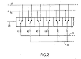
- FIG. 2 shows, very diagrammatically, the operation of the shift register 27 and the weighted tappings.
- Each stage is predetermined as requiring positive or negative weighting and the output is accordingly connected to a positive or negative summing line 31, 33.
- Each stage is represented by a two-position switch having alternative inputs connected to positive and negative supplies 45 and 47.
- the presence of a stored '0' signal value or a stored'1' (as coded by the coding circuits 22 of Figure 1) determine the position of the switch.
- the weighted resistors are connected to the positive or negative supplies.
- the lines 31 and 33 will therefore carry the sums of the weighted currents.
- the head-on direction of a particular transducer will be considered for target presence.
- a target on that particular heading will produce the necessary combination of 1's and 0's to produce a net output and a brightness modulation of the cathode-ray tube.
- Each pulse transmitted initiates the spiral scan and the time delay for the return of the pulse determines which of the many thousand 'circular' sweeps of the spiral highlights the individual targets. Range, direction and size are thus indicated.
- a significant advantage of a prefered embodiment of the invention is the ability to provide by interpolation, angular resolution better than the angle between successive transducers of the array of Figure 1.
- Figure 3 shows three shift registers 51, 52 and 53 each basically similar to the register 27 of Figure 1 and each having a similar array of positive and negative weighting -resistors RA1, RA2 etc; RB1, RB2 etc; and RC1, RC2 etc.
- the registers 51, 52 and 53 are each clocked as before by clock pulses (f c ) at the bit rate on line 25, but the three clock pulse signals are staggered regularly.
- a pulse distributor 61 consists of 3- stage cycling shift register which is clocked at three times the line 25 bit rate. The output from each stage provides a clock pulse for one of the registers 51, 52 and 53.
- the tap weighting resistors RA are the same are those in Figure 1.
- outputs from the differencing circuit 39 for register 51 correspond to target directions head-on, i.e. radially outwards, from each transducer.
- the weighting resistors are biased slightly off the symmetrical arrangement of register 51.
- the adjustment of the. weightings is such that the resulting beam lies one-third of the way between the original beam and that for the adjacent transducer.
- the tap weightings for register 53 are adjusted slightly further, taking the beam position one-third of the way from the next transducer.
- the three outputs, from the respective differencing circuits 39 are selected sequentially, by cycling switch 44 filtered and displayed as in Figure 1.
- the coders 22 may provide two-bit, or finer quantisation.
Landscapes
- Physics & Mathematics (AREA)
- Engineering & Computer Science (AREA)
- Acoustics & Sound (AREA)
- Multimedia (AREA)
- Measurement Of Velocity Or Position Using Acoustic Or Ultrasonic Waves (AREA)
Description
- This invention relates to sonar arrangements and particularly to such arrangements for providing a 360° scanning facility.
- US-A-3,810,082 (corresponding to DE-A-2,136,780A) discloses a circular array of electroacoustic transducer elements, each element being omni-directional, to transmit and/ or detect acoustic signals under water. Signals received from a particular 'target' source arrive at the various transducers with delays which vary from a minimum at the nearest transducer, and increasing with the more distance transducers in a non-linear manner. A shift register associated with each transducer receives a signal sample which can therefore be delayed by an amount dependent upon the length of the register, or the tapping at which the sample is extracted. By adjusting the tapping positions of the different registers therefore, a delay contour can be obtained such as to provide a directional beam. Rotations of the beam can then be obtained by loading a circulating register with all of the signal samples in parallel and connecting the shift registers to a selected group of the circulating register stages.
- Such a previously proposed system has certain deficiencies in regard to the accuracy of the delays that are provided, with the result that the beam tends to have side lobe irregularities. It also requires a very large number of transducers to give any very fine resolution of target direction.
- An object of the present invention is to provide a digital sonar arrangement giving good beam definition, and resolution of target direction.
- According to the present invention a sonar arrangement comprises a circular array of electroacoustic transducers; means for sampling the signal from each transducer in sequence; means for quantising the signal samples and sequentially feeding a digital representation of each signal sample to a shift register, said shift register incorporating sufficient stages to receive a plurality of cycles of signal samples and being tapped at a predetermined selection of said stages; and summing means arranged to sum the outputs of the tapped stages of said shift register, and is characterised in that the tappings at said predetermined selection of stages are individually weighted in either positive or negative senses with weighting means of appropriate sense and magnitude to provide phase compensation, over a plurality of cycles of stored signal samples, of the incoming signal at those transcuers whose signal samples instantaneously occupy said predetermined selection of stages, thereby to generate as the net output off said weighting and summing means, said rotating directional response beam.
- There is preferably a plurality of the shift registers connected to receive the digital representations of the transducer signals substantially in parallel, the magnitude of the tap weighting means of corresponding stages of the shift registers being slightly different so as to bias the effective beam direction from one shift register to another by a fraction of the angle between successive transducers. Thus one shift register may provide a selection of first beam directions aligned with the respective transducers and the remaining shift registers provide beam directions uniformly interpolated between the first beam directions.
- A sonar arrangement providing a 360°C scan will now be described, by way of example, with reference to the accompanying drawings, of which:
- Figure 1 shows a sonar system diagrammatically,
- Figure 2 is a diagram of a detail of the shift register appearing in Figure 1,
- and Figure 3 shows, again diagrammatically, a sonar system modified to provide direction interpolation.
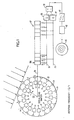
- Referring to Figure 1, an array of perhaps one hundred
electroacoustic transducers 21 form a circle (a smaller number being shown for convenience), each transucer having a wide beamwidth in the plane of the circle and the desired transverse beamwidth in the plane, which would normally be the vertical plane, at right angles to this. The electrical output of each transducer is digitally coded by a respective one-bit coder 22. The two bit values correspond to the positive and negative instantaneous values of the acoustic carrier signal. The coded values, or digital representations, are then sampled as indicated by a rotatingcontact switch 23. This mechanical switch is merely a diagrammatic illustration for in fact each transducer is connected to a respective electronic switch, for example a field effect transistor, these switches being enabled sequentially to connect thetransducer coders 22 sequentially to a common bar shown as thewiper connection 25 of theswitch 23. In an alternative arrangement a common coder in the 'wiper'lead 25 may replace theindividual coders 22. - The acoustic signal being detected may have a frequency (fo) up to may kilohertz, for example - 100 kHz. It is arranged that the period between samples at any one transducer is an integral number of acoustic signal periods plus or minus a quarter period thus giving quadrature data samples on successive scans. This both ensures that an impression of D.C. is not obtained by coincidental sampling of the same point-on-wave, and also provides a range of instantaneous signal values (even though coded to '1' or '0') for making up to a desired value. Thus,

- The
electronic switch 23 must in general operate at Nfs which is thus the sample rate (i.e. the bit rate) at thecommon connection 25. The one-bit samples (i.e. digital representations) are applied serially to ashift register 27 which is clocked at the same rate Nfs. In the above example this would be 1.75 MHz. - The
shift register 27 comprises a number of stages which is sufficient to accommodate several cycles of samples. It is desirable that the first sample derived from the transducer closest to the target, i.e. the 'head-on' transducer, is still in the shift register when the transducers on the diameter transverse to the target direction first intercept the advancing acoustic pulse. In the above case this implies about three cycles of samples and thus about three hundred stages. Such length gives the maximum scope for shaping the response beam. - The acoustic pulse typically has a pulse repetition rate of about one per second and a pulse duration of about 200 microseconds. Such a pulse does produce redundant samples in several cycles of the shift register but these merely produce a reduction in range descrimination.
- It is the object to bias the levels of the signals received by all (or at least a wide selection) of the 'illuminated' transducers to such values as would be received by a linear broadside array facing the target. Control of the actual received signals is impracticable so the shift register outputs are biased.
- Considering each cycle of the shift register, a particular stage, the same in each cycle, is selected for the 'target dead ahead' condition. When the target is dead ahead of the transducer corresponding to this stage in the cycle and the signal sample from that transducer is stored (transitorily) in that register stage, the other stored signal samples would be symmetrically distributed about that stage since they suffer symmetrical travel delays of the acoustic pulse. However, in addition to this (symmetrical) travel delay there is an asymmetry of the stored signal samples due to the scanning time of the
switch 23. Both of these effects are predictable, knowing the geometry of the array and the rotational frequency of theswitch 23. The selected stages of the register, from all three cycles are thus provided with weighted tapping resistors R1, R2, R3 etc. - In order to achieve the standard signal level of a broadside array certain of the signal samples require suppressing to varying extents and some require boosting. Consequently the two sets of tappings are connected to respective positive and
negative weighting lines amplifiers differencing circuit 39. The net output at each clock pulse is then applied to a low-pass filter 41, to adetector circuit 42 and then to an intensity modulated cathoderay tube display 43 driven by a spiral timebase system rotating in synchronism at the scan frequency. - As the
switch 23 scans around the transducers in synchronism with the stepping of the signal samples through the shift register, each transducer in turn, or rather the signal sample therefrom, will occupy the'dead ahead' stage in each cycle of the register. The beam formed by the weighted tappings will therefore relate to each transducer in turn and will effect a 360° scan around the array. - Figure 2 shows, very diagrammatically, the operation of the
shift register 27 and the weighted tappings. Each stage is predetermined as requiring positive or negative weighting and the output is accordingly connected to a positive ornegative summing line negative supplies coding circuits 22 of Figure 1) determine the position of the switch. Thus as the coded signal levels step through the register the weighted resistors are connected to the positive or negative supplies. Thelines - At each step of the shift register operation, the head-on direction of a particular transducer will be considered for target presence. A target on that particular heading will produce the necessary combination of 1's and 0's to produce a net output and a brightness modulation of the cathode-ray tube.
- Each pulse transmitted initiates the spiral scan and the time delay for the return of the pulse determines which of the many thousand 'circular' sweeps of the spiral highlights the individual targets. Range, direction and size are thus indicated.
- A significant advantage of a prefered embodiment of the invention is the ability to provide by interpolation, angular resolution better than the angle between successive transducers of the array of Figure 1. Figure 3 shows three
shift registers register 27 of Figure 1 and each having a similar array of positive and negative weighting -resistors RA1, RA2 etc; RB1, RB2 etc; and RC1, RC2 etc. - The
registers line 25, but the three clock pulse signals are staggered regularly. A pulse distributor 61 consists of 3- stage cycling shift register which is clocked at three times theline 25 bit rate. The output from each stage provides a clock pulse for one of theregisters - The tap weighting resistors RA are the same are those in Figure 1. Thus outputs from the
differencing circuit 39 forregister 51 correspond to target directions head-on, i.e. radially outwards, from each transducer. Forregister 52 however, the weighting resistors are biased slightly off the symmetrical arrangement ofregister 51. Thus the weightings are increased slightly on one side of the 'head on' stage and decreased to the other, with the result that the response beam for the array is shifted slightly. The adjustment of the. weightings is such that the resulting beam lies one-third of the way between the original beam and that for the adjacent transducer. - The tap weightings for
register 53 are adjusted slightly further, taking the beam position one-third of the way from the next transducer. - Thus, between each original output, from
register 51, there are two sequential outputs from the other two registers. The result is that the response beam is shifted around the array in angular steps one-third of that of the transducer spacing. - The three outputs, from the
respective differencing circuits 39 are selected sequentially, by cyclingswitch 44 filtered and displayed as in Figure 1. - There may of course be only one, or more than two, interpolation steps between successive transducers by the provision of appropriate shift registers, weighting resistors and clock pulse generator.
- In a modification of the basic coding arrangement the
coders 22 may provide two-bit, or finer quantisation. - It will be apparent that the weighted resistors and stage switches can be realised in practice by equivalent electronic logic circuitry.
Claims (4)
Applications Claiming Priority (2)
| Application Number | Priority Date | Filing Date | Title |
|---|---|---|---|
| GB8129090 | 1981-09-25 | ||
| GB8129090 | 1981-09-25 |
Publications (2)
| Publication Number | Publication Date |
|---|---|
| EP0076117A1 EP0076117A1 (en) | 1983-04-06 |
| EP0076117B1 true EP0076117B1 (en) | 1986-03-12 |
Family
ID=10524759
Family Applications (1)
| Application Number | Title | Priority Date | Filing Date |
|---|---|---|---|
| EP82305051A Expired EP0076117B1 (en) | 1981-09-25 | 1982-09-24 | Sonar arrangements |
Country Status (4)
| Country | Link |
|---|---|
| US (1) | US4525816A (en) |
| EP (1) | EP0076117B1 (en) |
| DE (1) | DE3269844D1 (en) |
| GB (1) | GB2109554B (en) |
Families Citing this family (2)
| Publication number | Priority date | Publication date | Assignee | Title |
|---|---|---|---|---|
| DE3932620A1 (en) * | 1989-09-29 | 1991-04-11 | Mantel Juval | LOCATION SYSTEM FOR SOUND IMPULSES |
| US6205224B1 (en) * | 1996-05-17 | 2001-03-20 | The Boeing Company | Circularly symmetric, zero redundancy, planar array having broad frequency range applications |
Family Cites Families (9)
| Publication number | Priority date | Publication date | Assignee | Title |
|---|---|---|---|---|
| US3370267A (en) * | 1965-10-23 | 1968-02-20 | Hughes Aircraft Co | Beam forming system |
| US3852707A (en) * | 1968-02-23 | 1974-12-03 | Us Navy | Sonar broadband constant beamwidth shading network |
| DE2163053C3 (en) * | 1971-07-23 | 1979-08-02 | Fried. Krupp Gmbh, 4300 Essen | Switching arrangement for the formation of chronologically successive group signals in direction finding technology |
| DE2136780C3 (en) * | 1971-07-23 | 1975-08-28 | Fried. Krupp Gmbh, 4300 Essen | Switching arrangement for forming temporally successive group signals from received signals, in particular in water-borne technology |
| FR2244180B1 (en) * | 1973-09-17 | 1977-08-19 | France Etat | |
| US4003016A (en) * | 1975-10-06 | 1977-01-11 | The United States Of America As Represented By The Secretary Of The Navy | Digital beamforming system |
| US4060792A (en) * | 1976-06-17 | 1977-11-29 | Raytheon Company | Hard clipped beam former |
| FR2432176A1 (en) * | 1978-07-25 | 1980-02-22 | Thomson Csf | FORMATION OF SONAR TRACKS BY LOAD TRANSFER DEVICES |
| US4233678A (en) * | 1979-03-12 | 1980-11-11 | The United States Of America As Represented By The Secretary Of The Navy | Serial phase shift beamformer using charge transfer devices |
-
1982
- 1982-09-23 US US06/421,960 patent/US4525816A/en not_active Expired - Fee Related
- 1982-09-24 DE DE8282305051T patent/DE3269844D1/en not_active Expired
- 1982-09-24 GB GB08227328A patent/GB2109554B/en not_active Expired
- 1982-09-24 EP EP82305051A patent/EP0076117B1/en not_active Expired
Also Published As
| Publication number | Publication date |
|---|---|
| GB2109554A (en) | 1983-06-02 |
| US4525816A (en) | 1985-06-25 |
| DE3269844D1 (en) | 1986-04-17 |
| EP0076117A1 (en) | 1983-04-06 |
| GB2109554B (en) | 1985-01-30 |
Similar Documents
| Publication | Publication Date | Title |
|---|---|---|
| US4368643A (en) | Ultrasonic imaging by radial scan beams emanating from a hypothetical point located behind linear transducer array | |
| EP0617796B1 (en) | A digital beamforming array | |
| US4974211A (en) | Digital ultrasound system with dynamic focus | |
| EP0161587B1 (en) | Phased array acoustic imaging system | |
| US4116229A (en) | Acoustic imaging apparatus | |
| US4060792A (en) | Hard clipped beam former | |
| JPS62280650A (en) | Ultrasonic signal delay method and device | |
| EP0249965B1 (en) | Ultrasonic apparatus | |
| US4728804A (en) | Scanning system with low sampling rate | |
| US3370267A (en) | Beam forming system | |
| US4215584A (en) | Method for transmission and reception of ultrasonic beams using ultrasonic transducer element array | |
| EP0395863A3 (en) | Aperture synthesized radiometer using digital beamforming techniques | |
| US3491360A (en) | Staggered pulse repetition frequency radar providing discrimination between first and second returns | |
| US4425634A (en) | Detection system | |
| US4288764A (en) | Signal processing devices | |
| EP0809376A9 (en) | Receiver synchronisation with timing and frequency error correction | |
| EP0256282B1 (en) | Ultrasonic wave diagnostic apparatus employing interpolated values of weighting data | |
| US4212084A (en) | Beam-former for FFT-based signal processor | |
| US4552020A (en) | Apparatus for the scanning of objects by means of ultrasound echography | |
| US4233678A (en) | Serial phase shift beamformer using charge transfer devices | |
| US4866449A (en) | Multichannel alignment system | |
| US4628738A (en) | Ultrasonic imaging device | |
| EP0076117B1 (en) | Sonar arrangements | |
| US6310832B1 (en) | Interpolated beamforming tracker | |
| US4727375A (en) | Process for adapting the post integration in a switched pulse repetition frequency radar and a circuit implementing this process |
Legal Events
| Date | Code | Title | Description |
|---|---|---|---|
| PUAI | Public reference made under article 153(3) epc to a published international application that has entered the european phase |
Free format text: ORIGINAL CODE: 0009012 |
|
| AK | Designated contracting states |
Designated state(s): DE FR SE |
|
| 17P | Request for examination filed |
Effective date: 19830913 |
|
| GRAA | (expected) grant |
Free format text: ORIGINAL CODE: 0009210 |
|
| AK | Designated contracting states |
Kind code of ref document: B1 Designated state(s): DE FR SE |
|
| REF | Corresponds to: |
Ref document number: 3269844 Country of ref document: DE Date of ref document: 19860417 |
|
| ET | Fr: translation filed | ||
| PLBI | Opposition filed |
Free format text: ORIGINAL CODE: 0009260 |
|
| 26 | Opposition filed |
Opponent name: KRUPP ATLAS ELEKTRONIK GMBH Effective date: 19860924 |
|
| RDAG | Patent revoked |
Free format text: ORIGINAL CODE: 0009271 |
|
| STAA | Information on the status of an ep patent application or granted ep patent |
Free format text: STATUS: PATENT REVOKED |
|
| 27W | Patent revoked |
Effective date: 19890205 |
|
| EUG | Se: european patent has lapsed |
Ref document number: 82305051.3 Effective date: 19890717 |