EP0075400B1 - Pool ball with a metal insert and method of manufacture - Google Patents
Pool ball with a metal insert and method of manufacture Download PDFInfo
- Publication number
- EP0075400B1 EP0075400B1 EP82304593A EP82304593A EP0075400B1 EP 0075400 B1 EP0075400 B1 EP 0075400B1 EP 82304593 A EP82304593 A EP 82304593A EP 82304593 A EP82304593 A EP 82304593A EP 0075400 B1 EP0075400 B1 EP 0075400B1
- Authority
- EP
- European Patent Office
- Prior art keywords
- ball
- mould
- insert
- metal ring
- cylindrical body
- Prior art date
- Legal status (The legal status is an assumption and is not a legal conclusion. Google has not performed a legal analysis and makes no representation as to the accuracy of the status listed.)
- Expired
Links
- 229910052751 metal Inorganic materials 0.000 title claims description 54
- 239000002184 metal Substances 0.000 title claims description 54
- 238000000034 method Methods 0.000 title claims description 13
- 238000004519 manufacturing process Methods 0.000 title claims description 8
- 239000000463 material Substances 0.000 claims description 13
- 239000000088 plastic resin Substances 0.000 claims description 8
- 239000007787 solid Substances 0.000 claims description 7
- 239000007769 metal material Substances 0.000 claims description 6
- 230000000284 resting effect Effects 0.000 claims description 4
- CWYNVVGOOAEACU-UHFFFAOYSA-N Fe2+ Chemical compound [Fe+2] CWYNVVGOOAEACU-UHFFFAOYSA-N 0.000 claims description 2
- 230000006698 induction Effects 0.000 description 6
- 239000011347 resin Substances 0.000 description 6
- 229920005989 resin Polymers 0.000 description 6
- 241000239290 Araneae Species 0.000 description 4
- 239000011521 glass Substances 0.000 description 4
- 239000000696 magnetic material Substances 0.000 description 3
- KXGFMDJXCMQABM-UHFFFAOYSA-N 2-methoxy-6-methylphenol Chemical compound [CH]OC1=CC=CC([CH])=C1O KXGFMDJXCMQABM-UHFFFAOYSA-N 0.000 description 2
- XEEYBQQBJWHFJM-UHFFFAOYSA-N Iron Chemical compound [Fe] XEEYBQQBJWHFJM-UHFFFAOYSA-N 0.000 description 2
- PXHVJJICTQNCMI-UHFFFAOYSA-N Nickel Chemical compound [Ni] PXHVJJICTQNCMI-UHFFFAOYSA-N 0.000 description 2
- 238000007796 conventional method Methods 0.000 description 2
- 239000005011 phenolic resin Substances 0.000 description 2
- 229920001568 phenolic resin Polymers 0.000 description 2
- 229920000728 polyester Polymers 0.000 description 2
- 229920001225 polyester resin Polymers 0.000 description 2
- 239000004645 polyester resin Substances 0.000 description 2
- 229910000831 Steel Inorganic materials 0.000 description 1
- 229910052782 aluminium Inorganic materials 0.000 description 1
- XAGFODPZIPBFFR-UHFFFAOYSA-N aluminium Chemical compound [Al] XAGFODPZIPBFFR-UHFFFAOYSA-N 0.000 description 1
- 238000001514 detection method Methods 0.000 description 1
- 229910003460 diamond Inorganic materials 0.000 description 1
- 239000010432 diamond Substances 0.000 description 1
- 239000012212 insulator Substances 0.000 description 1
- 229910052742 iron Inorganic materials 0.000 description 1
- 239000007788 liquid Substances 0.000 description 1
- 230000013011 mating Effects 0.000 description 1
- 150000002739 metals Chemical class 0.000 description 1
- 238000000465 moulding Methods 0.000 description 1
- 229910000595 mu-metal Inorganic materials 0.000 description 1
- 229910052759 nickel Inorganic materials 0.000 description 1
- 239000010959 steel Substances 0.000 description 1
Images
Classifications
-
- B—PERFORMING OPERATIONS; TRANSPORTING
- B29—WORKING OF PLASTICS; WORKING OF SUBSTANCES IN A PLASTIC STATE IN GENERAL
- B29D—PRODUCING PARTICULAR ARTICLES FROM PLASTICS OR FROM SUBSTANCES IN A PLASTIC STATE
- B29D99/00—Subject matter not provided for in other groups of this subclass
- B29D99/0042—Producing plain balls
-
- A—HUMAN NECESSITIES
- A63—SPORTS; GAMES; AMUSEMENTS
- A63B—APPARATUS FOR PHYSICAL TRAINING, GYMNASTICS, SWIMMING, CLIMBING, OR FENCING; BALL GAMES; TRAINING EQUIPMENT
- A63B37/00—Solid balls; Rigid hollow balls; Marbles
-
- A—HUMAN NECESSITIES
- A63—SPORTS; GAMES; AMUSEMENTS
- A63B—APPARATUS FOR PHYSICAL TRAINING, GYMNASTICS, SWIMMING, CLIMBING, OR FENCING; BALL GAMES; TRAINING EQUIPMENT
- A63B2209/00—Characteristics of used materials
- A63B2209/08—Characteristics of used materials magnetic
-
- A—HUMAN NECESSITIES
- A63—SPORTS; GAMES; AMUSEMENTS
- A63B—APPARATUS FOR PHYSICAL TRAINING, GYMNASTICS, SWIMMING, CLIMBING, OR FENCING; BALL GAMES; TRAINING EQUIPMENT
- A63B2243/00—Specific ball sports not provided for in A63B2102/00 - A63B2102/38
- A63B2243/002—Billiards
-
- A—HUMAN NECESSITIES
- A63—SPORTS; GAMES; AMUSEMENTS
- A63B—APPARATUS FOR PHYSICAL TRAINING, GYMNASTICS, SWIMMING, CLIMBING, OR FENCING; BALL GAMES; TRAINING EQUIPMENT
- A63B43/00—Balls with special arrangements
-
- B—PERFORMING OPERATIONS; TRANSPORTING
- B29—WORKING OF PLASTICS; WORKING OF SUBSTANCES IN A PLASTIC STATE IN GENERAL
- B29C—SHAPING OR JOINING OF PLASTICS; SHAPING OF MATERIAL IN A PLASTIC STATE, NOT OTHERWISE PROVIDED FOR; AFTER-TREATMENT OF THE SHAPED PRODUCTS, e.g. REPAIRING
- B29C70/00—Shaping composites, i.e. plastics material comprising reinforcements, fillers or preformed parts, e.g. inserts
- B29C70/68—Shaping composites, i.e. plastics material comprising reinforcements, fillers or preformed parts, e.g. inserts by incorporating or moulding on preformed parts, e.g. inserts or layers, e.g. foam blocks
-
- B—PERFORMING OPERATIONS; TRANSPORTING
- B29—WORKING OF PLASTICS; WORKING OF SUBSTANCES IN A PLASTIC STATE IN GENERAL
- B29L—INDEXING SCHEME ASSOCIATED WITH SUBCLASS B29C, RELATING TO PARTICULAR ARTICLES
- B29L2031/00—Other particular articles
- B29L2031/54—Balls
Definitions
- This invention relates to a pool ball with a metal insert and a method of manufacture thereof.
- Coin operated pool tables typically include passageways leading from each of the pockets to a locked compartment for retaining the pool balls as they are knocked into the pockets during the progress of a game.
- the compartment remains locked until a coin of proper denomination is deposited at which time the compartment opens to provide access to the pool balls therein.
- a cue ball for use in such coin operated pool tables must be separated from the object balls and prevented from entering the locked compartment in the event that the cue ball has been inadvertently scratched or knocked into one of the pockets during the progress of the game.
- Known methods of separating cue balls include providing a cue ball which is of a different size or weight than the object balls, detecting the difference mechanically and preventing the cue ball from entering the locked compartment. This has been found unacceptable since it is desirable that the cue ball have the same physical characteristics as the object balls.
- Another known method of separating the cue ball includes providing a cue ball having an insert of magnetic material located within the ball as near as possible to the surface thereof so that the cue ball may be directed into an unlocked compartment by means of a magnet.
- the magnetic cue ball may be formed having a hollow sphere of magnetic material with a perforation therein.
- a plastic resin is poured into the hollow sphere through the perforation to form a core.
- the core is then encapsulated in a shell of the plastic resin to form the cue ball.
- Another method of making a magnetic cue ball includes moulding plastic resin about a spherical cage formed of uniformly spaced steel strips.
- a magnetic cue ball may further be formed of a sphere of plastic resin having grooves therein. Strips of magnetic material are disposed within the grooves and the grooves filled with plastic resin to the outer surface of the ball.
- Still another method of separating a cue ball is to provide an induction coil located about a central passageway of the pool table and through which all of the pool balls roll. Downstream of the induction coil, the central passageway branches off into a passageway leading to the locked compartment for object balls and a passageway leading to an unlocked compartment for the cue ball.
- the field produced by the coil is affected such that the output of the coil signals an electronic circuit which actuates a mechanical kicker or the like disposed in the central passageway near the point at which the passageway branches off. The kicker when actuated knocks the cue ball into the passageway leading to the unlocked compartment.
- Known cue balls for use with an induction coil separating system have been formed with a solid spherical core of metal such as aluminum of the like and about which a plastic resin is moulded.
- the density of the metal material forming the insert has been a crucial design factor in manufacturing known cue balls with metal inserts. Because large quantities of metal are used to form the inserts, the density of the metal must be approximately equal to the density of the plastic resin forming the remainder of the ball. Therefore, only a limited number of metals having an appropriate density could heretofore be used.
- a method of making a pool ball having a spherical body of nonmetallic material and an insert in the form of a metal ring, the ball being formed in a ball mould having a generally spherical inner surface comprising forming a locating insert of nonmetallic material having a solid cylindrical body and a receiving surface for the metal ring, the length of the locating insert from an outermost end thereof to the centre of the receiving surface being equal to the radius of the ball mould, positioning a metal ring on the receiving surface of the locating insert, positioning the locating insert within the ball mould along a diameter of the mould with the outermost end of the locating insert resting on the generally spherical inner surface of the mould, the centre of mass of the metal ring being coincident with the geometric centre of the ball mould, and pouring nonmetallic material into the ball mould about the locating insert to form the body of the pool ball.
- the method of the invention is advantageous in that it simply and accurately locates the metal ring in the ball mould, the centre of mass of the metal ring coinciding with the geometric centre of the finished ball to provide a balanced cue ball, the size and weight of which is equal to that of the object balls.
- the metal ring may be extremely thin so that the density of the metal is not a crucial factor in obtaining a ball of standard weight.
- US-A-4116439 discloses a method of making a pool ball in which a pair of bottle caps are cemented to the opposite ends of a cylindrical metal member which is then positioned in the hemispherical cavity of a mould half having spider-forming half cylindrical recesses therein emanating from diametrically opposite locations of the hemispherical cavity.
- a similar mould half is mated with that mould half so that the two hemispherical cavities form a spherical cavity with the cylindrical metal member with its bottle caps positioned at its geometric centre and with the two spider-forming recesses of the one face those of the other to comprise cylindrical recesses, and polyester resin is then poured into the mould and allowed to cure.
- the resulting product is a spider insert in the form of a spherical polyester member surrounding the cylindrical member with its bottle caps and with a pair of diametrically opposite cylindrical polyester spider arms extending outwardly from the spherical member.
- the spider insert is then positioned in a pool ball mould with its arms located along a diameter of the mould and with the cylindrical metal member with its bottle caps positioned at the geometric centre of the mould by inserting the arms in grooves in the wall of a hemispherical ball mould and mating with it the other hemispherical half of the ball mould, and polyester resin is then poured into the ball mould about the spider insert to form the body of the pool ball.
- the cylindrical metal member with its bottle caps is positioned at the geometric centre of the pool ball.
- a body 10 of a cue ball 12 is formed of a nonmetallic material such as a phenolic resin poured into a conventional glass ball mould 14 having a generally spherical shape.
- a locating insert 16 formed of the same nonmetallic material as the body 10 of the ball is provided to accurately centre a metal ring 18 within the ball such that the centre of the mass of the ring 18 coincides with the geometric centre of the ball 12.
- the locating insert 16 may be moulded or machined having a solid cylindrical body 20 and shafts 22 and 24 extending outwardly from respective ends 26 and 28 along the longitudinal axis of the body 20.
- An annular groove 30 extends about the centre of the cylindrical body 20, the groove having a depth equal to the thickness of the metal ring 18 and a width equal to the width of the ring.
- the length of the insert from an outermost end 32 of the shaft 22 to the centre of the annular groove 30 is equal to the inner radius of the ball mould 14.
- a thin strip of metal material 34 is wrapped about the annular groove 30 to form the metal ring 18.
- the length of the metal strip 34 is approximately 6.35 mm (1/4") greater than the circumference of the annular groove 30 so that the ends of the metal strip may be overlapped and crimped together as shown at 36 to securely hold the metal ring 18 in position about the insert 16.
- the locating insert 16 with the metal ring 18 secured thereon is suspended within the glass ball mould 14 by conventional methods such that the insert is positioned along a diameter of the mould with the end 32 of the shaft 22 resting on the inner surface 38 of the mould.
- Liquid phenolic resin is poured through an opening 40 of the mould 14 about the insert 16.
- the filled mould is then heat cycle cured to a specific hardness after which the glass ball mould 14 is broken off the raw ball.
- the excess sprue resin 42 formed by the opening 40 of the mould 14 is removed by a chuck grinder.
- the raw ball is then ground in a centreless grinder to provide the finished spherical ball 12.
- the centre of mass of the metal ring coincides with the geometric centre of the ball 12 providing a balanced ball with a true roll.
- the cue ball 12 is particularly suitable for coin operated pool tables having an induction coil cue ball detection and separating system.
- the metal insert In order to detect the cue ball the metal insert must be sufficiently close to the outer surface of the ball since the resin comprising the body 10 of the ball acts as an insulator. It has been found that for a cue ball of standard size with a 57.15 mm (2-1/4") diameter, a ring 18 having a diameter of 15.875 mm (5/8") or greater, a width of about 15.875 mm (5/8"), and made of a ferrous metal such as Mu metal of approximately 80% nickel and 11-12% iron is easily detectable by an induction coil.
- the metal ring 18 may be extremely thin, having a thickness of about 0.025 mm (0.001"). Because such a small amount of metal is used to form the ring 18, the weight of the cue ball is not affected by the weight of the metal insert.
- a standard weight cue ball of 170 g (6 ounces) made in accordance with the present method may be obtained by using a resin having approximately the same density as the resin used in forming conventional pool balls.
- the insert 16 may be formed of a resin having a colour different from the resin forming the body 10 of the ball so that the cross section of the shafts 22 and 24 form a distinguishing mark 44 on the surface of the ball 12.
- the shafts 22 and 24 have a reduced cross-sectional area as compared to that of the cylindrical body 20 to provide a mark 44 as small in size as desired. Further the shafts may have a cross section of any desired shape such as a circle or a diamond to provide the distinguishing mark 44.
- the insert 16 as shown in Figs. 1-3 provides two distinguishing marks 44 on the outer surface of the ball 12 due to the shafts 22 and 24. Where only one mark 44 is desired, the insert may be formed having only one shaft 46 as shown for the insert 48 of Fig. 5.
- the insert 48 is identical to the insert 16 with shaft 24 eliminated.
- the insert 48 may be positioned within the ball mould 14 along a diameter of the mould by conventional techniques.
- the locating insert 50 includes a solid cylindrical body 52 having a diameter of 15.875 mm (5/8") or greater and a length equal to the width of the strip of metal 34 positioned thereon to form the metal ring.
- Shafts 54 and 56 extend outwardly from the cylindrical body 52 along its longitudinal axis.
- the shafts 54 and 56 have portions 58 and 60 in the form of truncated cones, the smaller bases of which abut cylindrical ends 62 and 64.
- the length of the insert 50 from the outermost end of a shaft 54, 56 to the centre of the cylindrical body 52 and thus the centre of the metal ring disposed thereon is equal to the radius of the glass ball mould so that the center of mass of the metal ring will coincide with the geometric centre of the cue ball 66.
- the cue ball 66 having the locating insert 50 is formed in the same manner as described with reference to Figs. 3.and 4 for the insert 16.
Landscapes
- Health & Medical Sciences (AREA)
- General Health & Medical Sciences (AREA)
- Physical Education & Sports Medicine (AREA)
- Engineering & Computer Science (AREA)
- Mechanical Engineering (AREA)
- Injection Moulding Of Plastics Or The Like (AREA)
Description
- This invention relates to a pool ball with a metal insert and a method of manufacture thereof.
- Coin operated pool tables typically include passageways leading from each of the pockets to a locked compartment for retaining the pool balls as they are knocked into the pockets during the progress of a game. The compartment remains locked until a coin of proper denomination is deposited at which time the compartment opens to provide access to the pool balls therein. A cue ball for use in such coin operated pool tables must be separated from the object balls and prevented from entering the locked compartment in the event that the cue ball has been inadvertently scratched or knocked into one of the pockets during the progress of the game.
- Known methods of separating cue balls include providing a cue ball which is of a different size or weight than the object balls, detecting the difference mechanically and preventing the cue ball from entering the locked compartment. This has been found unacceptable since it is desirable that the cue ball have the same physical characteristics as the object balls.
- Another known method of separating the cue ball includes providing a cue ball having an insert of magnetic material located within the ball as near as possible to the surface thereof so that the cue ball may be directed into an unlocked compartment by means of a magnet. As shown in US-A-3738655, the magnetic cue ball may be formed having a hollow sphere of magnetic material with a perforation therein. A plastic resin is poured into the hollow sphere through the perforation to form a core. The core is then encapsulated in a shell of the plastic resin to form the cue ball. Another method of making a magnetic cue ball includes moulding plastic resin about a spherical cage formed of uniformly spaced steel strips. A magnetic cue ball may further be formed of a sphere of plastic resin having grooves therein. Strips of magnetic material are disposed within the grooves and the grooves filled with plastic resin to the outer surface of the ball.
- Still another method of separating a cue ball is to provide an induction coil located about a central passageway of the pool table and through which all of the pool balls roll. Downstream of the induction coil, the central passageway branches off into a passageway leading to the locked compartment for object balls and a passageway leading to an unlocked compartment for the cue ball. When a cue ball having a metal insert therein rolls through the induction coil, the field produced by the coil is affected such that the output of the coil signals an electronic circuit which actuates a mechanical kicker or the like disposed in the central passageway near the point at which the passageway branches off. The kicker when actuated knocks the cue ball into the passageway leading to the unlocked compartment. Known cue balls for use with an induction coil separating system have been formed with a solid spherical core of metal such as aluminum of the like and about which a plastic resin is moulded.
- Numerous problems have arisen in manufacturing cue. balls having metal inserts therein as described above. One of the most apparent problems arises in centring the insert within the cue ball to provide a balanced ball having a true roll. The known methods of centring a solid spherical metal insert or an insert in the form of a spherical case are complex, costly and often inaccurate.
- Further, where it is desired to provide a cue ball of approximately the same weight as the object balls, the density of the metal material forming the insert has been a crucial design factor in manufacturing known cue balls with metal inserts. Because large quantities of metal are used to form the inserts, the density of the metal must be approximately equal to the density of the plastic resin forming the remainder of the ball. Therefore, only a limited number of metals having an appropriate density could heretofore be used.
- In accordance with the present invention there is provided a method of making a pool ball having a spherical body of nonmetallic material and an insert in the form of a metal ring, the ball being formed in a ball mould having a generally spherical inner surface, comprising forming a locating insert of nonmetallic material having a solid cylindrical body and a receiving surface for the metal ring, the length of the locating insert from an outermost end thereof to the centre of the receiving surface being equal to the radius of the ball mould, positioning a metal ring on the receiving surface of the locating insert, positioning the locating insert within the ball mould along a diameter of the mould with the outermost end of the locating insert resting on the generally spherical inner surface of the mould, the centre of mass of the metal ring being coincident with the geometric centre of the ball mould, and pouring nonmetallic material into the ball mould about the locating insert to form the body of the pool ball.
- Preferred features of this method are specified in claims 2 to 5.
- The method of the invention is advantageous in that it simply and accurately locates the metal ring in the ball mould, the centre of mass of the metal ring coinciding with the geometric centre of the finished ball to provide a balanced cue ball, the size and weight of which is equal to that of the object balls. Moreover, the metal ring may be extremely thin so that the density of the metal is not a crucial factor in obtaining a ball of standard weight.
- Attention is drawn to US-A-4116439 which discloses a method of making a pool ball in which a pair of bottle caps are cemented to the opposite ends of a cylindrical metal member which is then positioned in the hemispherical cavity of a mould half having spider-forming half cylindrical recesses therein emanating from diametrically opposite locations of the hemispherical cavity. A similar mould half is mated with that mould half so that the two hemispherical cavities form a spherical cavity with the cylindrical metal member with its bottle caps positioned at its geometric centre and with the two spider-forming recesses of the one face those of the other to comprise cylindrical recesses, and polyester resin is then poured into the mould and allowed to cure. When the mould halves are separated, the resulting product is a spider insert in the form of a spherical polyester member surrounding the cylindrical member with its bottle caps and with a pair of diametrically opposite cylindrical polyester spider arms extending outwardly from the spherical member. The spider insert is then positioned in a pool ball mould with its arms located along a diameter of the mould and with the cylindrical metal member with its bottle caps positioned at the geometric centre of the mould by inserting the arms in grooves in the wall of a hemispherical ball mould and mating with it the other hemispherical half of the ball mould, and polyester resin is then poured into the ball mould about the spider insert to form the body of the pool ball. In the resulting product, the cylindrical metal member with its bottle caps is positioned at the geometric centre of the pool ball.
- In accordance with the present invention there is further provided a pool ball having the features set out in claim 6.
- Preferred embodiments of this pool ball are specified in claims 7 to 13.
- In order that the invention may be well understood there will now be described some embodiments thereof, given by way of example, reference being made to the accompanying drawing, in which:
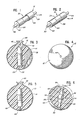
- Fig. 1 is an enlarged view of a locating insert;
- Fig. 2 is an enlarged view of the locating insert of Fig. 1 having a metal ring disposed thereon;
- Fig. 3 is a sectional view of a cue ball as formed in a mould;
- Fig. 4 is an enlarged view of the finished cue ball;
- Fig. 5 is a sectional view of another embodiment of the cue ball as formed in a mould; and
- Fig. 6 is a sectional view of a cue ball having another embodiment of the locating insert.
- As seen in Figs. 14, a
body 10 of a cue ball 12 is formed of a nonmetallic material such as a phenolic resin poured into a conventionalglass ball mould 14 having a generally spherical shape. A locatinginsert 16 formed of the same nonmetallic material as thebody 10 of the ball is provided to accurately centre ametal ring 18 within the ball such that the centre of the mass of thering 18 coincides with the geometric centre of the ball 12. - The locating
insert 16 may be moulded or machined having a solidcylindrical body 20 andshafts respective ends 26 and 28 along the longitudinal axis of thebody 20. Anannular groove 30 extends about the centre of thecylindrical body 20, the groove having a depth equal to the thickness of themetal ring 18 and a width equal to the width of the ring. The length of the insert from anoutermost end 32 of theshaft 22 to the centre of theannular groove 30 is equal to the inner radius of theball mould 14. - As seen in Fig. 2, a thin strip of
metal material 34 is wrapped about theannular groove 30 to form themetal ring 18. The length of themetal strip 34 is approximately 6.35 mm (1/4") greater than the circumference of theannular groove 30 so that the ends of the metal strip may be overlapped and crimped together as shown at 36 to securely hold themetal ring 18 in position about theinsert 16. - The locating
insert 16 with themetal ring 18 secured thereon is suspended within theglass ball mould 14 by conventional methods such that the insert is positioned along a diameter of the mould with theend 32 of theshaft 22 resting on theinner surface 38 of the mould. Liquid phenolic resin is poured through an opening 40 of themould 14 about theinsert 16. The filled mould is then heat cycle cured to a specific hardness after which theglass ball mould 14 is broken off the raw ball. Theexcess sprue resin 42 formed by the opening 40 of themould 14 is removed by a chuck grinder. The raw ball is then ground in a centreless grinder to provide the finished spherical ball 12. - Because the length of the
insert 16 from theend 32 to the centre of theannular groove 30 and thus the centre of themetal ring 18 is equal to the radius of theball mould 14, when the insert is positioned within the mould as described above, the centre of mass of the metal ring coincides with the geometric centre of the ball 12 providing a balanced ball with a true roll. - The cue ball 12 is particularly suitable for coin operated pool tables having an induction coil cue ball detection and separating system. In order to detect the cue ball the metal insert must be sufficiently close to the outer surface of the ball since the resin comprising the
body 10 of the ball acts as an insulator. It has been found that for a cue ball of standard size with a 57.15 mm (2-1/4") diameter, aring 18 having a diameter of 15.875 mm (5/8") or greater, a width of about 15.875 mm (5/8"), and made of a ferrous metal such as Mu metal of approximately 80% nickel and 11-12% iron is easily detectable by an induction coil. - Further, the
metal ring 18 may be extremely thin, having a thickness of about 0.025 mm (0.001"). Because such a small amount of metal is used to form thering 18, the weight of the cue ball is not affected by the weight of the metal insert. A standard weight cue ball of 170 g (6 ounces) made in accordance with the present method may be obtained by using a resin having approximately the same density as the resin used in forming conventional pool balls. - The
insert 16 may be formed of a resin having a colour different from the resin forming thebody 10 of the ball so that the cross section of theshafts shafts cylindrical body 20 to provide a mark 44 as small in size as desired. Further the shafts may have a cross section of any desired shape such as a circle or a diamond to provide the distinguishing mark 44. - The
insert 16 as shown in Figs. 1-3 provides two distinguishing marks 44 on the outer surface of the ball 12 due to theshafts shaft 46 as shown for theinsert 48 of Fig. 5. Theinsert 48 is identical to theinsert 16 withshaft 24 eliminated. Theinsert 48 may be positioned within theball mould 14 along a diameter of the mould by conventional techniques. - Another embodiment of a locating
insert 50 is shown in Fig. 6. The locatinginsert 50 includes a solidcylindrical body 52 having a diameter of 15.875 mm (5/8") or greater and a length equal to the width of the strip ofmetal 34 positioned thereon to form the metal ring.Shafts cylindrical body 52 along its longitudinal axis. Theshafts portions insert 50 from the outermost end of ashaft cylindrical body 52 and thus the centre of the metal ring disposed thereon is equal to the radius of the glass ball mould so that the center of mass of the metal ring will coincide with the geometric centre of thecue ball 66. Thecue ball 66 having the locatinginsert 50 is formed in the same manner as described with reference to Figs. 3.and 4 for theinsert 16.
Claims (13)
Applications Claiming Priority (2)
| Application Number | Priority Date | Filing Date | Title |
|---|---|---|---|
| US06/302,829 US4396192A (en) | 1981-09-16 | 1981-09-16 | Pool ball |
| US302829 | 1981-09-16 |
Publications (2)
| Publication Number | Publication Date |
|---|---|
| EP0075400A1 EP0075400A1 (en) | 1983-03-30 |
| EP0075400B1 true EP0075400B1 (en) | 1986-01-08 |
Family
ID=23169380
Family Applications (1)
| Application Number | Title | Priority Date | Filing Date |
|---|---|---|---|
| EP82304593A Expired EP0075400B1 (en) | 1981-09-16 | 1982-09-01 | Pool ball with a metal insert and method of manufacture |
Country Status (3)
| Country | Link |
|---|---|
| US (1) | US4396192A (en) |
| EP (1) | EP0075400B1 (en) |
| DE (1) | DE3268414D1 (en) |
Families Citing this family (6)
| Publication number | Priority date | Publication date | Assignee | Title |
|---|---|---|---|---|
| US4712333A (en) * | 1986-01-23 | 1987-12-15 | Huck Manufacturing Company | Tumbling media |
| US5042803A (en) * | 1988-11-28 | 1991-08-27 | Fox Cordell J | Billiards utilizing similar and dissimilar balls |
| NL1002739C2 (en) * | 1996-01-12 | 1997-05-21 | Standard Group Holding Bv | Method for enclosing an object with a transparent envelope. |
| US5941778A (en) * | 1998-02-09 | 1999-08-24 | Vasalech; Glen A. | Luminescent billiard game system |
| US20100112254A1 (en) * | 2007-03-21 | 2010-05-06 | Data F. S.R.L. | Coloured playing bowl |
| US9433267B1 (en) * | 2010-04-13 | 2016-09-06 | Levitation Jewelry LLC | Jewelry process |
Family Cites Families (10)
| Publication number | Priority date | Publication date | Assignee | Title |
|---|---|---|---|---|
| US3426121A (en) * | 1961-08-04 | 1969-02-04 | Albany Billiard Ball Co | A method of fabricating a plastic game ball |
| US3362710A (en) * | 1962-07-05 | 1968-01-09 | Valley Mfg Company | Methods and means for sorting pool balls |
| US3547439A (en) * | 1962-07-05 | 1970-12-15 | Valley Mfg Co | Pool balls separable by magnetic forces |
| US3738655A (en) * | 1962-07-05 | 1973-06-12 | Victor Comptometer Corp | Magnetic pool ball |
| US3937467A (en) * | 1973-11-05 | 1976-02-10 | Albany International Corporation | Billiard ball |
| US4116439A (en) * | 1976-09-30 | 1978-09-26 | C.F.F. Inc. | Pool ball |
| US4116435A (en) * | 1977-03-18 | 1978-09-26 | Randy D. Sines | Automatic cue ball separating device for billiard tables |
| US4142720A (en) * | 1977-08-09 | 1979-03-06 | Davis Frank E | Billiard ball |
| US4193596A (en) * | 1978-06-23 | 1980-03-18 | Baker Raymond J | Pool ball separator |
| US4214753A (en) * | 1978-08-21 | 1980-07-29 | Joseph L. Fernandez | Transparent article |
-
1981
- 1981-09-16 US US06/302,829 patent/US4396192A/en not_active Expired - Fee Related
-
1982
- 1982-09-01 EP EP82304593A patent/EP0075400B1/en not_active Expired
- 1982-09-01 DE DE8282304593T patent/DE3268414D1/en not_active Expired
Also Published As
| Publication number | Publication date |
|---|---|
| US4396192A (en) | 1983-08-02 |
| EP0075400A1 (en) | 1983-03-30 |
| DE3268414D1 (en) | 1986-02-20 |
Similar Documents
| Publication | Publication Date | Title |
|---|---|---|
| US4116439A (en) | Pool ball | |
| US3968582A (en) | Gaming token and process for fabricating same | |
| US6296190B1 (en) | Gaming chip with transponder and a method for making same | |
| US5692973A (en) | Golf ball | |
| US4396192A (en) | Pool ball | |
| US8079841B2 (en) | Golf ball and golf ball mold | |
| US4142720A (en) | Billiard ball | |
| US20030102595A1 (en) | Method of forming golf balls from surface-roughened molds | |
| US6863627B2 (en) | Golf ball cores with dual parting lines made from a three plate mold | |
| US4183527A (en) | Gyrostabilized bowling ball | |
| JPS555849A (en) | Molding method and die of reinforced plastic tube having annular groove | |
| US3738655A (en) | Magnetic pool ball | |
| US6478687B1 (en) | Golf cup with bearing insert | |
| JPS6262721A (en) | Injection mold | |
| US7547258B2 (en) | Golf ball | |
| US3828442A (en) | Golf ball sphericity gauge | |
| JP2000254254A (en) | Mold for golf ball and golf ball | |
| US20020192321A1 (en) | Mold-half | |
| US4214753A (en) | Transparent article | |
| US3426121A (en) | A method of fabricating a plastic game ball | |
| US3547439A (en) | Pool balls separable by magnetic forces | |
| US3937467A (en) | Billiard ball | |
| US6893362B2 (en) | Mold and method of molding golf ball having dimples on the equator | |
| JPS63158075A (en) | Golf ball | |
| EP1084736A1 (en) | Uniformly weighted golf ball |
Legal Events
| Date | Code | Title | Description |
|---|---|---|---|
| PUAI | Public reference made under article 153(3) epc to a published international application that has entered the european phase |
Free format text: ORIGINAL CODE: 0009012 |
|
| AK | Designated contracting states |
Designated state(s): DE FR GB |
|
| 17P | Request for examination filed |
Effective date: 19830408 |
|
| GRAA | (expected) grant |
Free format text: ORIGINAL CODE: 0009210 |
|
| AK | Designated contracting states |
Designated state(s): DE FR GB |
|
| REF | Corresponds to: |
Ref document number: 3268414 Country of ref document: DE Date of ref document: 19860220 |
|
| EN | Fr: translation not filed | ||
| PLBE | No opposition filed within time limit |
Free format text: ORIGINAL CODE: 0009261 |
|
| STAA | Information on the status of an ep patent application or granted ep patent |
Free format text: STATUS: NO OPPOSITION FILED WITHIN TIME LIMIT |
|
| 26N | No opposition filed | ||
| PGFP | Annual fee paid to national office [announced via postgrant information from national office to epo] |
Ref country code: GB Payment date: 19890831 Year of fee payment: 8 |
|
| PGFP | Annual fee paid to national office [announced via postgrant information from national office to epo] |
Ref country code: FR Payment date: 19890914 Year of fee payment: 8 |
|
| PGFP | Annual fee paid to national office [announced via postgrant information from national office to epo] |
Ref country code: DE Payment date: 19890915 Year of fee payment: 8 |
|
| PG25 | Lapsed in a contracting state [announced via postgrant information from national office to epo] |
Ref country code: GB Effective date: 19900901 |
|
| GBPC | Gb: european patent ceased through non-payment of renewal fee | ||
| PG25 | Lapsed in a contracting state [announced via postgrant information from national office to epo] |
Ref country code: DE Effective date: 19910601 |
|
| PG25 | Lapsed in a contracting state [announced via postgrant information from national office to epo] |
Ref country code: FR Free format text: LAPSE BECAUSE OF FAILURE TO SUBMIT A TRANSLATION OF THE DESCRIPTION OR TO PAY THE FEE WITHIN THE PRESCRIBED TIME-LIMIT Effective date: 20000930 |
|
| PG25 | Lapsed in a contracting state [announced via postgrant information from national office to epo] |
Ref country code: FR Free format text: LAPSE BECAUSE OF FAILURE TO SUBMIT A TRANSLATION OF THE DESCRIPTION OR TO PAY THE FEE WITHIN THE PRESCRIBED TIME-LIMIT Effective date: 19900930 |