EP0074810A2 - Subscription television system - Google Patents
Subscription television system Download PDFInfo
- Publication number
- EP0074810A2 EP0074810A2 EP82304758A EP82304758A EP0074810A2 EP 0074810 A2 EP0074810 A2 EP 0074810A2 EP 82304758 A EP82304758 A EP 82304758A EP 82304758 A EP82304758 A EP 82304758A EP 0074810 A2 EP0074810 A2 EP 0074810A2
- Authority
- EP
- European Patent Office
- Prior art keywords
- signal
- scrambled
- key
- scrambling
- program
- Prior art date
- Legal status (The legal status is an assumption and is not a legal conclusion. Google has not performed a legal analysis and makes no representation as to the accuracy of the status listed.)
- Granted
Links
- 230000004044 response Effects 0.000 claims abstract description 5
- 230000005540 biological transmission Effects 0.000 claims abstract 2
- 230000015654 memory Effects 0.000 claims description 20
- 230000005236 sound signal Effects 0.000 claims description 17
- 230000001360 synchronised effect Effects 0.000 claims description 4
- 238000000034 method Methods 0.000 description 33
- 238000010586 diagram Methods 0.000 description 9
- 101000860173 Myxococcus xanthus C-factor Proteins 0.000 description 7
- 239000003550 marker Substances 0.000 description 5
- 238000000926 separation method Methods 0.000 description 5
- 238000001514 detection method Methods 0.000 description 4
- 230000000694 effects Effects 0.000 description 4
- 230000008569 process Effects 0.000 description 4
- 230000003111 delayed effect Effects 0.000 description 3
- 230000008859 change Effects 0.000 description 2
- 238000006243 chemical reaction Methods 0.000 description 2
- 238000003780 insertion Methods 0.000 description 2
- 230000037431 insertion Effects 0.000 description 2
- 230000004048 modification Effects 0.000 description 2
- 238000012986 modification Methods 0.000 description 2
- 206010027336 Menstruation delayed Diseases 0.000 description 1
- 230000003321 amplification Effects 0.000 description 1
- 230000015556 catabolic process Effects 0.000 description 1
- 239000002131 composite material Substances 0.000 description 1
- 238000006731 degradation reaction Methods 0.000 description 1
- 239000000284 extract Substances 0.000 description 1
- 210000003128 head Anatomy 0.000 description 1
- 230000007246 mechanism Effects 0.000 description 1
- 231100000989 no adverse effect Toxicity 0.000 description 1
- 238000003199 nucleic acid amplification method Methods 0.000 description 1
- 230000002441 reversible effect Effects 0.000 description 1
- 230000035945 sensitivity Effects 0.000 description 1
- 230000002459 sustained effect Effects 0.000 description 1
- 230000000007 visual effect Effects 0.000 description 1
Images


Classifications
-
- G—PHYSICS
- G11—INFORMATION STORAGE
- G11B—INFORMATION STORAGE BASED ON RELATIVE MOVEMENT BETWEEN RECORD CARRIER AND TRANSDUCER
- G11B20/00—Signal processing not specific to the method of recording or reproducing; Circuits therefor
- G11B20/00086—Circuits for prevention of unauthorised reproduction or copying, e.g. piracy
- G11B20/0021—Circuits for prevention of unauthorised reproduction or copying, e.g. piracy involving encryption or decryption of contents recorded on or reproduced from a record carrier
-
- G—PHYSICS
- G11—INFORMATION STORAGE
- G11B—INFORMATION STORAGE BASED ON RELATIVE MOVEMENT BETWEEN RECORD CARRIER AND TRANSDUCER
- G11B20/00—Signal processing not specific to the method of recording or reproducing; Circuits therefor
- G11B20/00086—Circuits for prevention of unauthorised reproduction or copying, e.g. piracy
- G11B20/0021—Circuits for prevention of unauthorised reproduction or copying, e.g. piracy involving encryption or decryption of contents recorded on or reproduced from a record carrier
- G11B20/00217—Circuits for prevention of unauthorised reproduction or copying, e.g. piracy involving encryption or decryption of contents recorded on or reproduced from a record carrier the cryptographic key used for encryption and/or decryption of contents recorded on or reproduced from the record carrier being read from a specific source
- G11B20/00253—Circuits for prevention of unauthorised reproduction or copying, e.g. piracy involving encryption or decryption of contents recorded on or reproduced from a record carrier the cryptographic key used for encryption and/or decryption of contents recorded on or reproduced from the record carrier being read from a specific source wherein the key is stored on the record carrier
- G11B20/00282—Circuits for prevention of unauthorised reproduction or copying, e.g. piracy involving encryption or decryption of contents recorded on or reproduced from a record carrier the cryptographic key used for encryption and/or decryption of contents recorded on or reproduced from the record carrier being read from a specific source wherein the key is stored on the record carrier the key being stored in the content area, e.g. program area, data area or user area
-
- H—ELECTRICITY
- H04—ELECTRIC COMMUNICATION TECHNIQUE
- H04N—PICTORIAL COMMUNICATION, e.g. TELEVISION
- H04N5/00—Details of television systems
- H04N5/76—Television signal recording
- H04N5/91—Television signal processing therefor
- H04N5/913—Television signal processing therefor for scrambling ; for copy protection
-
- H—ELECTRICITY
- H04—ELECTRIC COMMUNICATION TECHNIQUE
- H04N—PICTORIAL COMMUNICATION, e.g. TELEVISION
- H04N7/00—Television systems
- H04N7/16—Analogue secrecy systems; Analogue subscription systems
- H04N7/167—Systems rendering the television signal unintelligible and subsequently intelligible
-
- H—ELECTRICITY
- H04—ELECTRIC COMMUNICATION TECHNIQUE
- H04N—PICTORIAL COMMUNICATION, e.g. TELEVISION
- H04N7/00—Television systems
- H04N7/16—Analogue secrecy systems; Analogue subscription systems
- H04N7/167—Systems rendering the television signal unintelligible and subsequently intelligible
- H04N7/1675—Providing digital key or authorisation information for generation or regeneration of the scrambling sequence
-
- G—PHYSICS
- G06—COMPUTING; CALCULATING OR COUNTING
- G06F—ELECTRIC DIGITAL DATA PROCESSING
- G06F2211/00—Indexing scheme relating to details of data-processing equipment not covered by groups G06F3/00 - G06F13/00
- G06F2211/007—Encryption, En-/decode, En-/decipher, En-/decypher, Scramble, (De-)compress
-
- H—ELECTRICITY
- H04—ELECTRIC COMMUNICATION TECHNIQUE
- H04N—PICTORIAL COMMUNICATION, e.g. TELEVISION
- H04N5/00—Details of television systems
- H04N5/76—Television signal recording
- H04N5/91—Television signal processing therefor
- H04N5/913—Television signal processing therefor for scrambling ; for copy protection
- H04N2005/91357—Television signal processing therefor for scrambling ; for copy protection by modifying the video signal
- H04N2005/91364—Television signal processing therefor for scrambling ; for copy protection by modifying the video signal the video signal being scrambled
Definitions
- This invention relates to a subscription television system and more particularly to a system in which televisioin signals are scrambled for broadcasting, the scrambled signals being transmitted in a form suitable for recording the transmitted signals by means of a recording and playback apparatus such as a video tape recorder.
- a television system comprising means for scrambling at least either one of the video signal and audio signal of specific programs in accordance with a predetermined scrambling scheme, characterised by means for generating a control signal in response to the predetermined scrambling scheme, said control signal including a key signal which is used for unscrambling the signal scrambled in said scrambling means, and means for transmitting said key signal after termination of said specific program.
- the invention also provides for use in a television system, apparatus for unscrambling signals of specific program transmitted in a scrambling form, said apparatus being characterised in that it comprises: a recording medium; memory means for storing a key signal which is transmitted after termination of said specific program; means for reproducing said scrambled signal from said recording medium; and means for unscrambling said scrambled signal from said reproducing means in accordance with said key signal read out from said memory means.
- a conventional helical scan type VTR is used as the VTR 1.
- the VTR comprises a tuner 4, a recording and playback apparatus 5 including a mechanism for recording and playback as well as circuitry, a modulator 6 which modulates a regenerated video signal and an audio signal onto a spare frequency channel.
- the modulated signals are applied to an antenna terminal (ANT) of the receiver 3 from an output terminal 7.
- Scrambled video and audio signals from the recording and playback apparatus 5 are applied to the decoder 2 via a terminal 8 and unscrambled therein to obtain the normal signals.
- the normal signals pass again through the VTR via an input terminal 9 and an output terminal 10 thereof and are applied to a LINE-IN terminal of the receiver 3.
- the unscrambled signals are converted into a signal in a spare frequency channel and are applied to the antenna terminal (ANT). If the unscrambled signals are not modulated onto a carrier, they are applied to the LINE-IN terminal.
- a start signal S 1 representing the start of the scrambled program
- a key discrimination signal S 2 used for identifying the kind of a key signal S5to be described later in detail, as shown in the drawing.
- a scrambled audio signal S 3 for the program is added.
- a write start signal S 4 for writing the key signal S 5 for unscrambling the scrambled signals S 3 (S 7 ) is added.
- a write stop signal S 6 is added.
- a vertical sync signal VD and a horizontal sync signal HD are added to the portions corresponding to that of the signals S 4 -S 6 in the audio channel.
- a 32 bit binary code signal using a NRZ modulation system is utilized for the signals S 1 , S 2 , S 4 , S 5 and S 6 in the audio channel excepting the program.
- This binary code signal is modulated in FSK mode and then superimposed on the television signals.
- "1" and "0" in the binary code are modulated into 1000Hz and 600Hz respectively.
- the VTR 1, decoder 2 and receiver 3 may be put into operation by detecting the start signal S 1 1
- the signal level of an optional field period in an optional given period of time of the i video signal is lowered by a required amount, and this procedure is repeated every such given period.
- the unscrambling operation at the receiving side would be accomplished by raising the gain of an amplifier at the intervals corresponding to the first and third fields of every five fields.
- the key in the case where the gain is raised is assumed to be "1”
- the key signal can be represented by a code pattern of "10100".
- the audio signal is also scrambled and unscrambled similarly.
- the unscrambling operation after completing the recording of the program in the VTR (1) will be accomplished by writing the key signal S 5 into the memory included in the decoder 2, and verifying the key signal S 5 with the reproduced signal while always reading the key signal S 5 may be changed every program or, every time, day, week or month so as to keep the contents thereof confidential to the personss other than the formal contractors. For this reason, when a large number of programs are recorded, various kinds of key signals will be written in the memory. In order to make possible the discrimination of which key code must be used to unscramble the desired program at the time of playback, the key discrimination signal S 2 is added ahead of the program.
- the key signal S 5 is added to the end of the program. For this reason, the scramble broadcasting cannot be watched in real time. The reproduction of the correct program becomes possible only after having been recorded in the tape by use of the VTR 1. If the key signal S 5 is not recorded in the tape, the unscrambling of a copy tape, if any, is not possible because there is no key. In addition, even if the key signal is recorded in a tape, unscrambling is not also possible so long as there is no decoder.
- the horizontal and vertical sync signals HD and VD are added in order to obtain clock pulses used in writing the key signals.
- the decoder 2 comprises an audio signal input terminal 15, a video signal input terminal 16, an audio signal output terminal 17, a video signal output terminal 18, a key signal demodulator 19, a sync separation circuit 20, a timing circuit 21, a code discriminator 22, a memory 23, an audio signal descrambler 24, a video signal descrambler 25 and switches 26, 27 and 28, etc.
- the switches 26 and 28 are open and the switch 27 is closed.
- the input terminal 15 is supplied with the signals S l - s 6 successively from the VTR 1 located at the preceding stage, and the input terminal 16 is supplied with the signals S 7 , VD and HD.
- the VTR is set to the recording mode E-E and the input terminals 15 and 16 are supplied with the signals for the motor.
- the start signal S1 in Figure 3 When the start signal S1 in Figure 3 is first detected by the code discriminator 22 from the signals applied to the input terminal 15, the respective circuits are operated in response to its detection. Next, if the key discrimination signal S 2 is detected and the kind of the key signal S 5 of the program is identified, the identification signal S 8 is written in the memory 23.
- the sync separation circuit 20 extracts the signals VD and HD from the scrambled video signal applied to the input terminal 16 and drives the timing circuit 21.
- the write start signal S 4 is detected and the memory 23 is switched to the write-in mode for the key signal S 5*
- the demodulator 19 demodulates the FSK-modulated key signal S 5 to obtain the binary coded key signal.
- This key signal is written in the memory 23 in a form corresponding to the identification signal S 8 after having been synchronized with the clock pulses through the timing circuit 21. Meanwhile, the signals VD and HD are supplied from the video channel and the write-in clocks synchronized with VD and HD are obtained. Alternatively, the arrangement must be such that when the write start signal S 4 is detected by the code discriminator 22, the key signal S 5 is not recorded on the tape by applying the detected signal to the VTR as shown by the dotted line in the drawing to stop the operation of the recording circuit. When the writing of the key signal S 5 ends, the write stop signal S 6 is detected and the writing operation is stopped.
- the scrambled video and audio signals and other signals ( S 1 , S 21 S 4 - S 6 and so on) are recorded in the tape, and the key signal for the program and the kind of the key signal are written in the memory 23.
- the aforesaid operation is performed every 6time a scrambled program is recorded, and the key signal for each program and the key discrimination signal therefor are written in the memory 23.
- the VTR 1 is set to the playback mode, and at the same time, the switches 26 and 28 are closed and the switch 27 is opened.
- the input terminal 15 is supplied with the signal obtained by modulating the signal reproduced from the audio track of the desired program recorded in the tape, and the input terminal 16 is supplied with the signal obtained by modulating the signal reproduced from the video track corresponding to the program.
- the reproduced key discrimination signal S 2 is detected by the code discriminator 22, the corresponding key signal recorded in the memory 23 is read out. This reading operation continues until the end of reproduction, and the read-out key signal is applied to the descramblers 24 and 25.
- the descramblers 24 and 25 unscramble the scrambled audio and video signals inputted thereto, depending on the code pattern of the key signal. In this case, if the scrambling method is one which utilizes the aforesaid level changes, the amplification for the time interval during which it is kept at its lower level is increased. If the scrambling method utilizes a signal order replacement system, the input signal is delayed, and during this delayed period, the signals are arranged or restored to the original order. The audio and video signals restroed to their original form by use of the descramblers 24 and 25 are applied to the receiver via the output terminals 17 and 18.
- the start signal S 1 or the key discrimination signal S2 may be used for finding the head of the tape at the time of playback by adding a code corresponding to the program thereto. It will be readily understood that the reading of the key discrimination signal from the memory may be made manually.
- the scrambled signals may be received by an ordinary receiver, it is required that the contents thereof may be kept as confidential as possible and the decoding of the key code used for unscrambling should not be easy.
- the VTR there are various impediments until the scrambled signals are recorded in the tape through the recording system, since various signal dispositions are required at the time of recording. The damage sustained at the time of recording remains as the incompleteness of the unscrambling at the time of playback and deteriorates its picture quality.
- the scrambled broadcast must be recorded on the VTR
- the scrambled signals can pass through the recording system without any problem, the scrambling effect can be made large without disturbing the correlation between the signals, particularly in the case of the VTR for home use, and the unscrambling in the decoder can be made with ease.
- the following method takes the abovementioned points into consideration.
- This method is the simplest one in which the signal level is changed based on one field unit as shown in Figure 5.
- the levels in the fourth, seventh and ninth fields are lowered by 2 - 3 dB. Since the sensitivity of human eyes is particularly high to plane flickering, a severe scramble effect can be obtained even with slight fluctuation of the intensity.
- a marker signal S 9 is inserted every tenth field, and the scrambling is performed by regarding ten fields to be one cycle. According to typical visual characteristics, the human eye is most sensitive to flicker at a frequency of 10 - 20 Hz, so that the key code pattern may be determined by regarding it to be one cycle.
- the level of C signal (chroma signal) is also changed at the same ratio since otherwise the ratio of Y to C varies temporarily.
- the composite Y + C signal can be scrambled as it is at the broadcasting station, and overmodulation of the chroma signal may be avoided. Since the ACC operation at the receiving side, in general, is slow and tracking of the burst signals is not possible, the addition of scramble effect to colour flicker may be possible. If the burst signal is made to change in level, the scrambling process will be simple.
- the process may become rather complex, but it will be easy to obtain comparatiively large level changes.
- the VTR since the VTR is so designed that the ACC has a high speed response during playback, the recording and playback can be performed without any trouble.
- Figure 6 shows an example of the scrambler for carrying out the above described flicker method.
- a set-up detection circuit 33, a marker generator 34 and a scramble code generator 35 are operated based on VD and HD extracted by the sync separation circuit 32 from the Y + C signal applied to an input terminal 31.
- a switch 36 is opened or closed according to the scramble code, the Y + C signal is changed in its level or scrambled according to the code pattern in synchronism with the field detection by means of the set up detection circuit 33.
- This scrambled signal is applied to an adder 37 and outputted after having been summed with the output of an adder 38, that is, the summed output of the marker signal and the scramble code.
- the aforesaid scramble code corresponds to the key signal 8 5 .
- the scrambling of the C signal is performed by changing the phase of the burst signal in field units. Since this method modulates only the phase, there is no adverse effect on the signal-to-noise ratio even if it is passed through the VTR, and no 5 disturbance is introduced into the correlation of the o ignal. For this reason, a high quality signal may be assured upon unscrambling. In addition, it can be realized without performing the separation that may cause a degradation of signal.
- Figure 7 shows an example of scrambler which performs the aforesaid method.
- a burst signal extracted by a burst gate 40 from the Y + C signal applied to an input terminal 39 is applied to an adder 41.
- the extracted burst signal is also phase shifted to 90°, 180° and 270° by phase shifters 42, 43 and 44, respectively, and then applied to a switch 45.
- a scramble code generator 47 is driven by VD and HD from a sync separation circuit 46, and the switch 45 is successively switched by the scramble codes from the generator 47.
- the burst signal phase shifted from 0° up to 270 successively is added to the Y + C signal at the adder 41 and then outputted.
- the APC of the receiver can usually follow every field, so that the hue changes every field.
- scrambling will be performed by randomly changing the 12 Hz chroma flicker as well as the hue.
- the signal is recorded in the tape as it is since the control system can follow the burst phase without any delay. Accordingly, the original hue can be obtained by decoding it in the opposite sequence at the time of playback.
- This method may also be accomplished by switching the combination of at least two phases or of a large number of phases in many different forms. In more concrete form, it may also be accomplished by inserting the market signal once every scramble cycle.
- one period of time represented by 1H is divided into two parts, and the Latter half is shifted to the position corresponding to the first half of the subsequent period of time H. If this signal is then received by an ordinary receiver, a picture whose left and right halves are shifted as shown in Figure 9B will be obtained (the normal picture is shown in Figure 9A).
- Figure 10 shows one form of the scrambler based on the aforesaid method.
- the scrambled signals shown in Figure 8 are obtained by delaying the input signal through a 0.6H delay circuit 48 constituted by a charge coupled device (CCD) or bucket brigade device (BBD).
- the CCD is driven by a clock n times higher than the HD frequency from a clock generator 49.
- Two switches 50 and 51 are open for the period of horizontal blanking.
- this method can be realized by replacing the input signal or a signal obtained by delaying the input signal by 1H with the 0.5H delayed ooutput by means of a switch, and selecting the input signal or the 1H delayed output at the aforesaid insertion point.
- Figure 11 shows another arrangement wherein the normal screen is divided into four parts so as to be replaced in the desired order. This method can be readily realized by appropriately combinging a 1/2 delay circuit and a 1/4 delay circuit.
- a pseudo-ghost can be obtained by delaying the input signal by approximately 1 sec and changing over the switch every field.
- This method will be realized by reading, in the direction opposite to the one at the time of writing, the signal written a line interval at a time into the memory regarding it as one field unit and combining with the normal field.
- Figure 13 shows an example of scrambler for performing the aforesaid method.
- the input signal is first subjected to A/D conversion and then alternately written in two 1H memories via a switch which is changted one every 1H. While one side is written, the other wise will be read.
- the up-down counter which controls the memory location being accessed counts up, whereas at the time of reading, it counts down causing read out in the opposite direction.
- the read-out signal is taken out through the right switch (also toggled every 1H) and subjected to D/A conversion.
- the D/A output and the original input signal are alternately outputted every one field through the switch to be switched every one field. If the scrambled signals are received an ordinary receiver, a overlapped picture consisting of the normal picture and the picture reversed left to right will be reproduced on the screen.
- the reordering of the signal is perforrmed using six fields as one unit.
- a length of more than six fields (approx. 100 m.sec), for example, since, if the abovementioned unit is too short, the contents thereof may be discriminated.
- a marker signal indicative of the six field unit must be inserted, but the market signal (for example, the market signal S 9 in Figure 5) used for scrambling the aforesaid video signal can be utilized as the marker for the audio signal.
- Figure 15 shows a scrambler which can be used for practicing the method of Figure 14.
- a delay circuit BBD having a delay time of six fields always performs the writing and the reading of the input audio signal by the clock synchronized with VD for the video signal.
- the read-out signal and the original audio signal are alternately selected every twelfth field by the switch.
- the signals corresponding to the second, fourth, sixth fields in Figure 14 can be taken out as they are, and the signals corresponding to the first, third, fifth fields can be taken out with some delay. Needless to say, various forms of order replacement patterns may be used.
- This method is based on the substantially same process as explained in connection with the scrambling method (5) for the video signal. As illustrated in Figure 16, the signal is written in the memory in six field units and then read out in the opposite direction continuously or in a combination of normal and reverse according to a desired pattern.
- Figure 17 shows a form of the scrambler for use in this method.
- a six field memory performs the writing in the up direction with the help of an up/down counter and the reading in the down direction.
- the read-out signal and the original signal are selected by means of a switch and then outputted.
- the changover of this switch is performed by the timing corresponding to the scramble pattern in Figure 16.
- the scrambled program is provided at .ts end with the key signal used at the time of unscrambling, it becomes impossible to watch the scramble broadcasting in real time, and the use of the recording and playback apparatus such as the VTR with the decoder is required to obtain the correct program.
- the type of VTR and the modification required for the VTR will be minimum.
Abstract
Description
- This invention relates to a subscription television system and more particularly to a system in which televisioin signals are scrambled for broadcasting, the scrambled signals being transmitted in a form suitable for recording the transmitted signals by means of a recording and playback apparatus such as a video tape recorder.
- In recent years, there has been proposed a scramble broadcasting system in which a specific program is transmitted by a broadcasting station after having been scrambled and the transmitted program can be received by only subscribers having special decoders based on a contract with the broadcasting station, and experimental local broadcasting is in progress on a small scale. In scrambled broadcasting the television signals of specific program are scrambled by changing the level thereof extending over an optional period or altering the order of the signals and then transmitted from the broadcasting station. Accordingly, even if the television signals in the scrambled broadcast are received by an ordinary or conventional receiver, correct pictures and sound cannot be reproduced. Normal pictures and sound can be received only by subscribers who have made a contract with the broadcasting station and have a decoder which can unscramble the signals previously scrambled at the transmitting station.
- In a scrambled broadcasting system it is desirable to satisfy the following conditions:
- (1) Simultaneous unscrambling cannot be done while receiving the scrambled program, i.e. the reception of a correct program is not possible in real time.
- (2) The program must be recorded by the VTR before reproduction.
- (3) To play the tape on which the program is recorded, a VTR with a decoder must be used to reproduce the program correctly.
- (4) Any type of VTR can be used.
- (5) Modification for the conventional VTR, required for adding a decoder thereto, must be at a minimum.
- (6) The scramble broadcast is put on the air during an idle time such as midnight, without utilizing an ordinary broadcasting time slot.
- It is one object to provide improved subscription television system in which a scrambled television signal can be broadcast.
- It is another object to provide a system in which the broadcasting scrambled television signal is temporarily recorded in a recorder and upon reproduction thereof, the scrambled television signal is unscrambled to enable the television signal to display on the TV screen.
- In accordance with this invention, there is provided a television system comprising means for scrambling at least either one of the video signal and audio signal of specific programs in accordance with a predetermined scrambling scheme, characterised by means for generating a control signal in response to the predetermined scrambling scheme, said control signal including a key signal which is used for unscrambling the signal scrambled in said scrambling means, and means for transmitting said key signal after termination of said specific program.
- The invention also provides for use in a television system, apparatus for unscrambling signals of specific program transmitted in a scrambling form, said apparatus being characterised in that it comprises: a recording medium; memory means for storing a key signal which is transmitted after termination of said specific program; means for reproducing said scrambled signal from said recording medium; and means for unscrambling said scrambled signal from said reproducing means in accordance with said key signal read out from said memory means.
- Other features of the invention are characterised in the subclaims.
- These and other features and advantages of the invention will become apparent from the following more detailed description taken in conjunction with the accompanying drawings, in which:-
- Figures I and 2 are block diagrams showing receivving components of a subscription television system in which the present invention may be used;
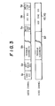
- Figure 3 shows the format of the transmitted signal in an embodiment of this invention;
- Figure 4 is a block diagram showing one form of the decoder illustrated in Figure 1;
- Figure 5 is a graph showing one example of scrambled video signal;
- Figure 6 is a block diagram of a scramble circuit which performs the scrambling operation as shown in Figure 5;
- Figure 7 is a block diagram showing another form of scramble circuit;
- Figure 8 is a graph showing another example of scrambled video signal;
- Figure 9 shows a picture on TV screen when the video signal scrambled as shown in Figure 8 is reproduced as it is;
- Figure 10 is a block diagram of scramble circuit which performs the scrambling operation as shown in Figure 8;
- Figure 11 shows another picture on TV screen when the scrambled video signal is reproduced as it is;
- Figures 12 and 13 are block diagrams of other scramble circuits;
- Figure 14 is a graph which is used for explaining the scrambling of the audio signal of the television signal;
- Figure 15 is a block diagram of the scramble circuit which performs the scrambling operation shown in Figure 14;
- Figure 16 is a graph which is used for explaining another way of scrambling the audio signal; and
- Figure 17 is a block diagram of the scramble circuit which performs the scrambling operation shown in Figure 16.
- Reference is first primarily directed to the block diagrams of Figures 1 and 2 which illustrate a typical conection of a
VTR 1, adecoder 2 and areceiver 3. - In Figure 1, a conventional helical scan type VTR is used as the
VTR 1. The VTR comprises atuner 4, a recording andplayback apparatus 5 including a mechanism for recording and playback as well as circuitry, amodulator 6 which modulates a regenerated video signal and an audio signal onto a spare frequency channel. The modulated signals are applied to an antenna terminal (ANT) of thereceiver 3 from anoutput terminal 7. Scrambled video and audio signals from the recording andplayback apparatus 5 are applied to thedecoder 2 via aterminal 8 and unscrambled therein to obtain the normal signals. The normal signals pass again through the VTR via aninput terminal 9 and anoutput terminal 10 thereof and are applied to a LINE-IN terminal of thereceiver 3. - Referring now to Figure 2 wherein a modulator 11 is incorporated in the
decoder 2, the unscrambled signals are converted into a signal in a spare frequency channel and are applied to the antenna terminal (ANT). If the unscrambled signals are not modulated onto a carrier, they are applied to the LINE-IN terminal. - In Figure 3, there are indicated the contents of the signal to be transmitted when a certain program is to be broadcast in scrambled form.
- In the audio channel, there are added a start signal S1 representing the start of the scrambled program, and a key discrimination signal S2 used for identifying the kind of a key signal S5to be described later in detail, as shown in the drawing. Next, a scrambled audio signal S3 for the program is added. When the program is completed, a write start signal S4 for writing the key signal S5 for unscrambling the scrambled signals S3(S7) is added. Finally, a write stop signal S6 is added. In the video channel, subsequent to the scrambled program video signal S7 corresponding to the signal S3 in the audio channel, a vertical sync signal VD and a horizontal sync signal HD are added to the portions corresponding to that of the signals S4-S6 in the audio channel.
- A 32 bit binary code signal using a NRZ modulation system, for example, is utilized for the signals S1, S2, S4, S5 and S6 in the audio channel excepting the program. This binary code signal is modulated in FSK mode and then superimposed on the television signals. In this case, for example, "1" and "0" in the binary code are modulated into 1000Hz and 600Hz respectively.
- When the scrambled program is to be broadcast late at night, the
VTR 1,decoder 2 andreceiver 3 may be put into operation by detecting thestart signal S 11 - Assume now that a certain program is to be scrambled by changing the level of signal in one field unit. In this case, the signal level of an optional field period in an optional given period of time of the i video signal, for example, is lowered by a required amount, and this procedure is repeated every such given period. For example, assuming that the given period is divided into five fields and only the first and third fields of said five fields are lowered in its level, the unscrambling operation at the receiving side would be accomplished by raising the gain of an amplifier at the intervals corresponding to the first and third fields of every five fields. If the key in the case where the gain is raised is assumed to be "1", the key signal can be represented by a code pattern of "10100". Whereas, the audio signal is also scrambled and unscrambled similarly.
- In the illustrated embodiments, the unscrambling operation after completing the recording of the program in the VTR (1), will be accomplished by writing the key signal S5 into the memory included in the
decoder 2, and verifying the key signal S5 with the reproduced signal while always reading the key signal S5 may be changed every program or, every time, day, week or month so as to keep the contents thereof confidential to the personss other than the formal contractors. For this reason, when a large number of programs are recorded, various kinds of key signals will be written in the memory. In order to make possible the discrimination of which key code must be used to unscramble the desired program at the time of playback, the key discrimination signal S2 is added ahead of the program. - As previously stated, in the illustrated embodiment, the key signal S5 is added to the end of the program. For this reason, the scramble broadcasting cannot be watched in real time. The reproduction of the correct program becomes possible only after having been recorded in the tape by use of the
VTR 1. If the key signal S5 is not recorded in the tape, the unscrambling of a copy tape, if any, is not possible because there is no key. In addition, even if the key signal is recorded in a tape, unscrambling is not also possible so long as there is no decoder. The horizontal and vertical sync signals HD and VD are added in order to obtain clock pulses used in writing the key signals. - Next, one form of the
decoder 2 will be explained in detail in conjunction with Figure 4. - The
decoder 2, as shown in the drawing, comprises an audiosignal input terminal 15, a videosignal input terminal 16, an audiosignal output terminal 17, a videosignal output terminal 18, akey signal demodulator 19, async separation circuit 20, atiming circuit 21, acode discriminator 22, amemory 23, an audio signal descrambler 24, avideo signal descrambler 25 and switches 26, 27 and 28, etc. - At the time of recording, the
switches switch 27 is closed. Theinput terminal 15 is supplied with the signals Sl - s6 successively from theVTR 1 located at the preceding stage, and theinput terminal 16 is supplied with the signals S7, VD and HD. At this juncture, the VTR is set to the recording mode E-E and theinput terminals - When the start signal S1 in Figure 3 is first detected by the
code discriminator 22 from the signals applied to theinput terminal 15, the respective circuits are operated in response to its detection. Next, if the key discrimination signal S2 is detected and the kind of the key signal S5 of the program is identified, the identification signal S8 is written in thememory 23. Thesync separation circuit 20 extracts the signals VD and HD from the scrambled video signal applied to theinput terminal 16 and drives thetiming circuit 21. When the program ends, the write start signal S4 is detected and thememory 23 is switched to the write-in mode for the key signal S5* Then, thedemodulator 19 demodulates the FSK-modulated key signal S5 to obtain the binary coded key signal. This key signal is written in thememory 23 in a form corresponding to the identification signal S8 after having been synchronized with the clock pulses through thetiming circuit 21. Meanwhile, the signals VD and HD are supplied from the video channel and the write-in clocks synchronized with VD and HD are obtained. Alternatively, the arrangement must be such that when the write start signal S4 is detected by thecode discriminator 22, the key signal S5 is not recorded on the tape by applying the detected signal to the VTR as shown by the dotted line in the drawing to stop the operation of the recording circuit. When the writing of the key signal S5 ends, the write stop signal S6 is detected and the writing operation is stopped. As a result, the scrambled video and audio signals and other signals (S 1, S21 S4 - S6 and so on) are recorded in the tape, and the key signal for the program and the kind of the key signal are written in thememory 23. The aforesaid operation is performed every 6time a scrambled program is recorded, and the key signal for each program and the key discrimination signal therefor are written in thememory 23. - At the time of playback, the
VTR 1 is set to the playback mode, and at the same time, theswitches switch 27 is opened. Theinput terminal 15 is supplied with the signal obtained by modulating the signal reproduced from the audio track of the desired program recorded in the tape, and theinput terminal 16 is supplied with the signal obtained by modulating the signal reproduced from the video track corresponding to the program. First of all, when the reproduced key discrimination signal S2 is detected by thecode discriminator 22, the corresponding key signal recorded in thememory 23 is read out. This reading operation continues until the end of reproduction, and the read-out key signal is applied to thedescramblers 24 and 25. Thedescramblers 24 and 25 unscramble the scrambled audio and video signals inputted thereto, depending on the code pattern of the key signal. In this case, if the scrambling method is one which utilizes the aforesaid level changes, the amplification for the time interval during which it is kept at its lower level is increased. If the scrambling method utilizes a signal order replacement system, the input signal is delayed, and during this delayed period, the signals are arranged or restored to the original order. The audio and video signals restroed to their original form by use of thedescramblers 24 and 25 are applied to the receiver via theoutput terminals - Various scrambling methods will be hereinafter explained in detail.
- As the scrambled signals may be received by an ordinary receiver, it is required that the contents thereof may be kept as confidential as possible and the decoding of the key code used for unscrambling should not be easy. In the VTR, there are various impediments until the scrambled signals are recorded in the tape through the recording system, since various signal dispositions are required at the time of recording. The damage sustained at the time of recording remains as the incompleteness of the unscrambling at the time of playback and deteriorates its picture quality. Accordingly, in the system according to the present invention wherein the scrambled broadcast must be recorded on the VTR, it is desirable that the scrambled signals can pass through the recording system without any problem, the scrambling effect can be made large without disturbing the correlation between the signals, particularly in the case of the VTR for home use, and the unscrambling in the decoder can be made with ease. The following method takes the abovementioned points into consideration.
- As the first step, the scrambling method for the video signal will be explained.
- This method is the simplest one in which the signal level is changed based on one field unit as shown in Figure 5. In the drawing, the levels in the fourth, seventh and ninth fields are lowered by 2 - 3 dB. Since the sensitivity of human eyes is particularly high to plane flickering, a severe scramble effect can be obtained even with slight fluctuation of the intensity. In the example of Figure 5, a marker signal S9 is inserted every tenth field, and the scrambling is performed by regarding ten fields to be one cycle. According to typical visual characteristics, the human eye is most sensitive to flicker at a frequency of 10 - 20 Hz, so that the key code pattern may be determined by regarding it to be one cycle. In reality, it may be sufficient to change only the level of the Y (luminous) signal, but it is more preferable that the level of C signal (chroma signal) is also changed at the same ratio since otherwise the ratio of Y to C varies temporarily. In this case, the composite Y + C signal can be scrambled as it is at the broadcasting station, and overmodulation of the chroma signal may be avoided. Since the ACC operation at the receiving side, in general, is slow and tracking of the burst signals is not possible, the addition of scramble effect to colour flicker may be possible. If the burst signal is made to change in level, the scrambling process will be simple. If the level of the burst signal is assumed to be constant, the process may become rather complex, but it will be easy to obtain comparatiively large level changes. On the other hand, since the VTR is so designed that the ACC has a high speed response during playback, the recording and playback can be performed without any trouble.
- Figure 6 shows an example of the scrambler for carrying out the above described flicker method.
- A set-up
detection circuit 33, amarker generator 34 and a scramble code generator 35 are operated based on VD and HD extracted by thesync separation circuit 32 from the Y + C signal applied to aninput terminal 31. When aswitch 36 is opened or closed according to the scramble code, the Y + C signal is changed in its level or scrambled according to the code pattern in synchronism with the field detection by means of the set updetection circuit 33. This scrambled signal is applied to anadder 37 and outputted after having been summed with the output of anadder 38, that is, the summed output of the marker signal and the scramble code. In this case, the aforesaid scramble code corresponds to thekey signal 85. - In this method, the scrambling of the C signal is performed by changing the phase of the burst signal in field units. Since this method modulates only the phase, there is no adverse effect on the signal-to-noise ratio even if it is passed through the VTR, and no 5 disturbance is introduced into the correlation of the oignal. For this reason, a high quality signal may be assured upon unscrambling. In addition, it can be realized without performing the separation that may cause a degradation of signal.
- Figure 7 shows an example of scrambler which performs the aforesaid method.
- A burst signal extracted by a
burst gate 40 from the Y + C signal applied to aninput terminal 39 is applied to anadder 41. The extracted burst signal is also phase shifted to 90°, 180° and 270° byphase shifters switch 45. Ascramble code generator 47 is driven by VD and HD from async separation circuit 46, and theswitch 45 is successively switched by the scramble codes from thegenerator 47. The burst signal phase shifted from 0° up to 270 successively is added to the Y + C signal at theadder 41 and then outputted. - When the phase rotation of the burst signal is performed by this circuit for every field, the APC of the receiver can usually follow every field, so that the hue changes every field. In this example, scrambling will be performed by randomly changing the 12 Hz chroma flicker as well as the hue. At the time of recording by means of the VTR, the signal is recorded in the tape as it is since the control system can follow the burst phase without any delay. Accordingly, the original hue can be obtained by decoding it in the opposite sequence at the time of playback. This method may also be accomplished by switching the combination of at least two phases or of a large number of phases in many different forms. In more concrete form, it may also be accomplished by inserting the market signal once every scramble cycle.
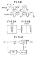
- In the example of Figure 8, one period of time represented by 1H is divided into two parts, and the Latter half is shifted to the position corresponding to the first half of the subsequent period of time H. If this signal is then received by an ordinary receiver, a picture whose left and right halves are shifted as shown in Figure 9B will be obtained (the normal picture is shown in Figure 9A).
- Figure 10 shows one form of the scrambler based on the aforesaid method.
- The scrambled signals shown in Figure 8 are obtained by delaying the input signal through a 0.6
H delay circuit 48 constituted by a charge coupled device (CCD) or bucket brigade device (BBD). The CCD is driven by a clock n times higher than the HD frequency from a clock generator 49. Two switches 50 and 51 are open for the period of horizontal blanking. - If the normal signal is inserted into the scrambled signal of Figure 8 in field units, the scramble effect will be further improved and the unscrambling will be made more difficult. If the insertion process is performed by a key code, the decoding operation will become more difficult. In Figure 10, this method can be realized by replacing the input signal or a signal obtained by delaying the input signal by 1H with the 0.5H delayed ooutput by means of a switch, and selecting the input signal or the 1H delayed output at the aforesaid insertion point.
- Figure 11 shows another arrangement wherein the normal screen is divided into four parts so as to be replaced in the desired order. This method can be readily realized by appropriately combinging a 1/2 delay circuit and a 1/4 delay circuit.
- As illustrated in Figure 12, a pseudo-ghost can be obtained by delaying the input signal by approximately 1 sec and changing over the switch every field.
- This method will be realized by reading, in the direction opposite to the one at the time of writing, the signal written a line interval at a time into the memory regarding it as one field unit and combining with the normal field.
- Figure 13 shows an example of scrambler for performing the aforesaid method. As seen from the drawing, the input signal is first subjected to A/D conversion and then alternately written in two 1H memories via a switch which is changted one every 1H. While one side is written, the other wise will be read. During writing, the up-down counter which controls the memory location being accessed counts up, whereas at the time of reading, it counts down causing read out in the opposite direction. The read-out signal is taken out through the right switch (also toggled every 1H) and subjected to D/A conversion. The D/A output and the original input signal are alternately outputted every one field through the switch to be switched every one field. If the scrambled signals are received an ordinary receiver, a overlapped picture consisting of the normal picture and the picture reversed left to right will be reproduced on the screen.
- Next, the scrambling method on the audio signal will be explained by way of examples.
- As shown in Figure 14, the reordering of the signal is perforrmed using six fields as one unit. In the case of audio signal, it will be preferable to have a length of more than six fields (approx. 100 m.sec), for example, since, if the abovementioned unit is too short, the contents thereof may be discriminated. In this case, a marker signal indicative of the six field unit must be inserted, but the market signal (for example, the market signal S9 in Figure 5) used for scrambling the aforesaid video signal can be utilized as the marker for the audio signal.
- Figure 15 shows a scrambler which can be used for practicing the method of Figure 14.
- A delay circuit BBD having a delay time of six fields always performs the writing and the reading of the input audio signal by the clock synchronized with VD for the video signal. The read-out signal and the original audio signal are alternately selected every twelfth field by the switch. Thus, the signals corresponding to the second, fourth, sixth fields in Figure 14 can be taken out as they are, and the signals corresponding to the first, third, fifth fields can be taken out with some delay. Needless to say, various forms of order replacement patterns may be used.
- This method is based on the substantially same process as explained in connection with the scrambling method (5) for the video signal. As illustrated in Figure 16, the signal is written in the memory in six field units and then read out in the opposite direction continuously or in a combination of normal and reverse according to a desired pattern.
- Figure 17 shows a form of the scrambler for use in this method. In the drawing, a six field memory performs the writing in the up direction with the help of an up/down counter and the reading in the down direction. The read-out signal and the original signal are selected by means of a switch and then outputted. The changover of this switch is performed by the timing corresponding to the scramble pattern in Figure 16.
- As previously described, according to the present invention, since the scrambled program is provided at .ts end with the key signal used at the time of unscrambling, it becomes impossible to watch the scramble broadcasting in real time, and the use of the recording and playback apparatus such as the VTR with the decoder is required to obtain the correct program. As stated above, there is no limitation to the type of VTR and the modification required for the VTR will be minimum.
- In addition, since the code signal (signal S2) denoting the kind of key signal is added to the start portion of the program, the key signal corresponding too the desired program can be checked prior to its playback.
Claims (7)
Priority Applications (1)
| Application Number | Priority Date | Filing Date | Title |
|---|---|---|---|
| AT82304758T ATE25908T1 (en) | 1981-09-10 | 1982-09-09 | SUBSCRIPTION TELEVISION SYSTEM. |
Applications Claiming Priority (4)
| Application Number | Priority Date | Filing Date | Title |
|---|---|---|---|
| JP56142836A JPS5843685A (en) | 1981-09-10 | 1981-09-10 | Television signal sending-out system |
| JP142836/81 | 1981-09-10 | ||
| JP142837/81 | 1981-09-10 | ||
| JP56142837A JPS5844873A (en) | 1981-09-10 | 1981-09-10 | Television signal recording and reproducing device |
Publications (3)
| Publication Number | Publication Date |
|---|---|
| EP0074810A2 true EP0074810A2 (en) | 1983-03-23 |
| EP0074810A3 EP0074810A3 (en) | 1984-06-27 |
| EP0074810B1 EP0074810B1 (en) | 1987-03-11 |
Family
ID=26474718
Family Applications (1)
| Application Number | Title | Priority Date | Filing Date |
|---|---|---|---|
| EP82304758A Expired EP0074810B1 (en) | 1981-09-10 | 1982-09-09 | Subscription television system |
Country Status (5)
| Country | Link |
|---|---|
| US (1) | US4533949A (en) |
| EP (1) | EP0074810B1 (en) |
| AU (1) | AU562395B2 (en) |
| CA (1) | CA1200007A (en) |
| DE (1) | DE3275697D1 (en) |
Cited By (8)
| Publication number | Priority date | Publication date | Assignee | Title |
|---|---|---|---|---|
| EP0120615A1 (en) * | 1983-02-28 | 1984-10-03 | Sony Corporation | Apparatus for, and method of, recording scrambled or coded television signals |
| EP0120685A2 (en) * | 1983-03-24 | 1984-10-03 | Sony Corporation | Method of and apparatus for decoding scrambled video signals |
| WO1985004024A1 (en) * | 1984-02-28 | 1985-09-12 | Ted Struik | A system for recording images and relating sound |
| EP0260886A2 (en) * | 1986-09-19 | 1988-03-23 | The Titan Corporation | Video scrambling by segmenting video information lines |
| EP0123505B1 (en) * | 1983-04-21 | 1989-09-27 | General Instrument Corporation | Scrambling system for television video signal |
| FR2650931A1 (en) * | 1989-08-04 | 1991-02-15 | Samsung Electronics Co Ltd | DECODER SWITCH CIRCUIT FOR MAGNETOSCOPES |
| US5058159A (en) * | 1989-06-15 | 1991-10-15 | Macrovision Corporation | Method and system for scrambling and descrambling audio information signals |
| FR2700092A1 (en) * | 1992-12-29 | 1994-07-01 | France Telecom | Method of broadcasting programs with conditional access allowing progressive access and method of progressive access to such programs. |
Families Citing this family (33)
| Publication number | Priority date | Publication date | Assignee | Title |
|---|---|---|---|---|
| US4965825A (en) | 1981-11-03 | 1990-10-23 | The Personalized Mass Media Corporation | Signal processing apparatus and methods |
| USRE47642E1 (en) | 1981-11-03 | 2019-10-08 | Personalized Media Communications LLC | Signal processing apparatus and methods |
| US7831204B1 (en) | 1981-11-03 | 2010-11-09 | Personalized Media Communications, Llc | Signal processing apparatus and methods |
| US4575755A (en) * | 1982-12-14 | 1986-03-11 | Tocom, Inc. | Video encoder/decoder system |
| JPS59152786A (en) * | 1983-02-18 | 1984-08-31 | Sanyo Electric Co Ltd | Scrambling system in catv broadcast |
| JPS59165585A (en) * | 1983-03-09 | 1984-09-18 | Sony Corp | Television signal receiver |
| US4626909A (en) * | 1983-05-03 | 1986-12-02 | Sony Corporation | Video signal recording and reproducing system with automatic channel and time selection |
| US4613901A (en) * | 1983-05-27 | 1986-09-23 | M/A-Com Linkabit, Inc. | Signal encryption and distribution system for controlling scrambling and selective remote descrambling of television signals |
| JPS6016082A (en) * | 1983-07-07 | 1985-01-26 | Sony Corp | Transmission system of scramble television signal |
| JPS6016083A (en) * | 1983-07-07 | 1985-01-26 | Sony Corp | Television signal transmission system |
| CA1213972A (en) * | 1983-07-13 | 1986-11-12 | Takashi Okada | Apparatus for scrambling a television signal |
| US4636852A (en) * | 1984-01-26 | 1987-01-13 | Scientific-Atlanta, Inc. | Scrambling and descrambling of television signals for subscription TV |
| US4750053A (en) * | 1984-02-02 | 1988-06-07 | Broadcast Advertisers Reports, Inc. | Method and system for enabling television commerical monitoring using a marking signal superimposed over an audio signal |
| US4751732A (en) * | 1984-07-06 | 1988-06-14 | Kabushiki Kaisha Toshiba | Broadcasting system |
| BE901468A (en) * | 1985-01-09 | 1985-05-02 | Belge Radio Television | INFORMATION ENCODING AND DECODING METHOD AND APPARATUS FOR IMPLEMENTING IT. |
| US4796299A (en) * | 1985-08-22 | 1989-01-03 | Itt Corporation | Video encoder apparatus |
| US4893248A (en) * | 1987-02-06 | 1990-01-09 | Access Corporation | Monitoring and reporting system for remote terminals |
| DE3850530T2 (en) * | 1987-06-30 | 1994-10-27 | Toshiba Kawasaki Kk | Recording / playback system and method with recording restriction function. |
| US5394274A (en) * | 1988-01-22 | 1995-02-28 | Kahn; Leonard R. | Anti-copy system utilizing audible and inaudible protection signals |
| US5058157A (en) * | 1989-09-06 | 1991-10-15 | Macrovision Corporation | Method and apparatus for encrypting and decrypting time domain signals |
| US5046092A (en) * | 1990-03-29 | 1991-09-03 | Gte Laboratories Incorporated | Video control system for transmitted programs |
| US5046090A (en) * | 1990-03-29 | 1991-09-03 | Gte Laboratories Incorporated | Recorded medium for video control system |
| US4991208A (en) * | 1990-03-29 | 1991-02-05 | Gte Laboratories Incorporated | Video control system having session encryption key |
| US5262874A (en) * | 1990-06-06 | 1993-11-16 | Macrovision Corporation | Method and apparatus for recording and replaying field-length-modulated video signals |
| EP0632445B1 (en) * | 1993-06-07 | 2002-01-23 | Hitachi, Ltd. | Digital information recording-reproducing apparatus |
| US5525110A (en) * | 1993-10-29 | 1996-06-11 | The Torrington Company | Universal joint |
| JPH07231424A (en) * | 1994-02-18 | 1995-08-29 | Hitachi Ltd | Recording/reproducing system and device therefor |
| JP3397975B2 (en) * | 1996-06-07 | 2003-04-21 | 三洋電機株式会社 | 3D image scramble method |
| JP4110588B2 (en) * | 1997-03-19 | 2008-07-02 | ソニー株式会社 | Data receiving apparatus and receiving method |
| BR9815610A (en) * | 1997-08-01 | 2004-06-22 | Scientific Atlanta | Verification of program information source in conditional access system |
| JP3011157B2 (en) * | 1997-10-30 | 2000-02-21 | 日本電気株式会社 | Image reading method and apparatus |
| US6674858B1 (en) * | 1997-12-10 | 2004-01-06 | Hitachi, Ltd. | Receiving device, recording and reproducing device and receiving/recording-reproducing system for digital broadcast signal |
| JP3565715B2 (en) * | 1998-07-02 | 2004-09-15 | 松下電器産業株式会社 | Broadcast system and broadcast transceiver |
Citations (3)
| Publication number | Priority date | Publication date | Assignee | Title |
|---|---|---|---|---|
| US3919462A (en) * | 1973-08-15 | 1975-11-11 | System Dev Corp | Method and apparatus for scrambling and unscrambling communication signals |
| WO1980002901A1 (en) * | 1979-06-15 | 1980-12-24 | Telediffusion Fse | Television system with access control using a variable electronic key |
| GB2067871A (en) * | 1980-01-19 | 1981-07-30 | Marconi Co Ltd | Information Encoding Systems |
Family Cites Families (7)
| Publication number | Priority date | Publication date | Assignee | Title |
|---|---|---|---|---|
| US2857455A (en) * | 1953-12-01 | 1958-10-21 | Rca Corp | Subscription color television system |
| US4225884A (en) * | 1977-02-14 | 1980-09-30 | Telease, Inc. | Method and system for subscription television billing and access |
| US4250524A (en) * | 1979-02-22 | 1981-02-10 | Clarion Co., Ltd. | Validation apparatus in a pay television system |
| US4403252A (en) * | 1980-05-27 | 1983-09-06 | R F Monolithics, Inc. | Television scrambling and unscrambling method and apparatus |
| US4389671A (en) * | 1980-09-29 | 1983-06-21 | Harris Corporation | Digitally-controlled analog encrypton |
| US4405942A (en) * | 1981-02-25 | 1983-09-20 | Telease, Inc. | Method and system for secure transmission and reception of video information, particularly for television |
| US4430669A (en) * | 1981-05-29 | 1984-02-07 | Payview Limited | Transmitting and receiving apparatus for permitting the transmission and reception of multi-tier subscription programs |
-
1982
- 1982-09-07 AU AU88072/82A patent/AU562395B2/en not_active Expired
- 1982-09-08 US US06/415,836 patent/US4533949A/en not_active Expired - Lifetime
- 1982-09-08 CA CA000410966A patent/CA1200007A/en not_active Expired
- 1982-09-09 EP EP82304758A patent/EP0074810B1/en not_active Expired
- 1982-09-09 DE DE8282304758T patent/DE3275697D1/en not_active Expired
Patent Citations (3)
| Publication number | Priority date | Publication date | Assignee | Title |
|---|---|---|---|---|
| US3919462A (en) * | 1973-08-15 | 1975-11-11 | System Dev Corp | Method and apparatus for scrambling and unscrambling communication signals |
| WO1980002901A1 (en) * | 1979-06-15 | 1980-12-24 | Telediffusion Fse | Television system with access control using a variable electronic key |
| GB2067871A (en) * | 1980-01-19 | 1981-07-30 | Marconi Co Ltd | Information Encoding Systems |
Cited By (13)
| Publication number | Priority date | Publication date | Assignee | Title |
|---|---|---|---|---|
| EP0120615A1 (en) * | 1983-02-28 | 1984-10-03 | Sony Corporation | Apparatus for, and method of, recording scrambled or coded television signals |
| EP0120685A3 (en) * | 1983-03-24 | 1986-02-19 | Sony Corporation | Method of and apparatus for decoding scrambled video signals |
| EP0120685A2 (en) * | 1983-03-24 | 1984-10-03 | Sony Corporation | Method of and apparatus for decoding scrambled video signals |
| EP0123505B1 (en) * | 1983-04-21 | 1989-09-27 | General Instrument Corporation | Scrambling system for television video signal |
| WO1985004024A1 (en) * | 1984-02-28 | 1985-09-12 | Ted Struik | A system for recording images and relating sound |
| EP0260886A2 (en) * | 1986-09-19 | 1988-03-23 | The Titan Corporation | Video scrambling by segmenting video information lines |
| EP0260886A3 (en) * | 1986-09-19 | 1989-06-14 | The Titan Corporation | Video scrambling by segmenting video information lines |
| US5058159A (en) * | 1989-06-15 | 1991-10-15 | Macrovision Corporation | Method and system for scrambling and descrambling audio information signals |
| FR2650931A1 (en) * | 1989-08-04 | 1991-02-15 | Samsung Electronics Co Ltd | DECODER SWITCH CIRCUIT FOR MAGNETOSCOPES |
| NL8902007A (en) * | 1989-08-04 | 1991-03-01 | Samsung Electronics Co Ltd | CHANNEL + DECODER SWITCH CHAIN FOR VIDEO CASSETTE REGISTRATION DEVICES. |
| FR2700092A1 (en) * | 1992-12-29 | 1994-07-01 | France Telecom | Method of broadcasting programs with conditional access allowing progressive access and method of progressive access to such programs. |
| WO1994015437A1 (en) * | 1992-12-29 | 1994-07-07 | France Telecom | Conditional access programme broadcasting method enabling gradual access, and gradual programme access method |
| BE1007882A3 (en) * | 1992-12-29 | 1995-11-14 | France Telecom | Method for broadcasting conditional access program enabling gradual process of access access and programs as a progressive. |
Also Published As
| Publication number | Publication date |
|---|---|
| AU8807282A (en) | 1983-03-17 |
| EP0074810B1 (en) | 1987-03-11 |
| DE3275697D1 (en) | 1987-04-16 |
| US4533949A (en) | 1985-08-06 |
| EP0074810A3 (en) | 1984-06-27 |
| AU562395B2 (en) | 1987-06-11 |
| CA1200007A (en) | 1986-01-28 |
Similar Documents
| Publication | Publication Date | Title |
|---|---|---|
| EP0074810B1 (en) | Subscription television system | |
| EP0120615B1 (en) | Apparatus for, and method of, recording scrambled or coded television signals | |
| US4222068A (en) | Subscription television apparatus and methods | |
| US4458268A (en) | Sync displacement scrambling | |
| US4635113A (en) | Apparatus for descrambling transmitted scrambled television signals | |
| US4628359A (en) | Memory selecting system for scrambled television receiver | |
| US4700388A (en) | Apparatus for scrambling a television signal | |
| JPS59210782A (en) | Television set | |
| CA1233232A (en) | Television signal transmission system | |
| US4636855A (en) | Scrambled television signal receiver system | |
| JPH037193B2 (en) | ||
| JPH0462237B2 (en) | ||
| JPS58131874A (en) | Television signal transmission system | |
| JPH0237749B2 (en) | ||
| JPH0462238B2 (en) | ||
| JPH057917B2 (en) | ||
| US5508814A (en) | Method for transmitting index information in video tape recorder | |
| JPS6065686A (en) | Television signal transmission system | |
| JPH057918B2 (en) | ||
| JPS58131873A (en) | Television signal transmission system | |
| JPS58131872A (en) | Television signal transmission system |
Legal Events
| Date | Code | Title | Description |
|---|---|---|---|
| PUAI | Public reference made under article 153(3) epc to a published international application that has entered the european phase |
Free format text: ORIGINAL CODE: 0009012 |
|
| AK | Designated contracting states |
Designated state(s): AT BE CH DE FR GB LI LU NL |
|
| 17P | Request for examination filed |
Effective date: 19830905 |
|
| PUAL | Search report despatched |
Free format text: ORIGINAL CODE: 0009013 |
|
| AK | Designated contracting states |
Designated state(s): AT BE CH DE FR GB LI LU NL |
|
| GRAA | (expected) grant |
Free format text: ORIGINAL CODE: 0009210 |
|
| AK | Designated contracting states |
Kind code of ref document: B1 Designated state(s): AT BE CH DE FR GB LI LU NL |
|
| REF | Corresponds to: |
Ref document number: 25908 Country of ref document: AT Date of ref document: 19870315 Kind code of ref document: T |
|
| REF | Corresponds to: |
Ref document number: 3275697 Country of ref document: DE Date of ref document: 19870416 |
|
| ET | Fr: translation filed | ||
| PLBE | No opposition filed within time limit |
Free format text: ORIGINAL CODE: 0009261 |
|
| STAA | Information on the status of an ep patent application or granted ep patent |
Free format text: STATUS: NO OPPOSITION FILED WITHIN TIME LIMIT |
|
| 26N | No opposition filed | ||
| EPTA | Lu: last paid annual fee | ||
| PGFP | Annual fee paid to national office [announced via postgrant information from national office to epo] |
Ref country code: FR Payment date: 20010911 Year of fee payment: 20 |
|
| PGFP | Annual fee paid to national office [announced via postgrant information from national office to epo] |
Ref country code: GB Payment date: 20010912 Year of fee payment: 20 Ref country code: AT Payment date: 20010912 Year of fee payment: 20 |
|
| PGFP | Annual fee paid to national office [announced via postgrant information from national office to epo] |
Ref country code: CH Payment date: 20010914 Year of fee payment: 20 |
|
| PGFP | Annual fee paid to national office [announced via postgrant information from national office to epo] |
Ref country code: DE Payment date: 20010924 Year of fee payment: 20 |
|
| PGFP | Annual fee paid to national office [announced via postgrant information from national office to epo] |
Ref country code: NL Payment date: 20010927 Year of fee payment: 20 |
|
| PGFP | Annual fee paid to national office [announced via postgrant information from national office to epo] |
Ref country code: BE Payment date: 20010928 Year of fee payment: 20 |
|
| PGFP | Annual fee paid to national office [announced via postgrant information from national office to epo] |
Ref country code: LU Payment date: 20011002 Year of fee payment: 20 |
|
| REG | Reference to a national code |
Ref country code: GB Ref legal event code: IF02 |
|
| PG25 | Lapsed in a contracting state [announced via postgrant information from national office to epo] |
Ref country code: LI Free format text: LAPSE BECAUSE OF EXPIRATION OF PROTECTION Effective date: 20020908 Ref country code: GB Free format text: LAPSE BECAUSE OF EXPIRATION OF PROTECTION Effective date: 20020908 Ref country code: CH Free format text: LAPSE BECAUSE OF EXPIRATION OF PROTECTION Effective date: 20020908 |
|
| PG25 | Lapsed in a contracting state [announced via postgrant information from national office to epo] |
Ref country code: LU Free format text: LAPSE BECAUSE OF EXPIRATION OF PROTECTION Effective date: 20020909 Ref country code: NL Free format text: LAPSE BECAUSE OF EXPIRATION OF PROTECTION Effective date: 20020909 Ref country code: AT Free format text: LAPSE BECAUSE OF EXPIRATION OF PROTECTION Effective date: 20020909 |
|
| BE20 | Be: patent expired |
Owner name: *SONY CORP. Effective date: 20020909 |
|
| REG | Reference to a national code |
Ref country code: GB Ref legal event code: PE20 Effective date: 20020908 |
|
| REG | Reference to a national code |
Ref country code: CH Ref legal event code: PL |
|
| NLV7 | Nl: ceased due to reaching the maximum lifetime of a patent |
Effective date: 20020909 |