EP0074129B1 - Method and apparatus for turning filled cartons with positive assist - Google Patents
Method and apparatus for turning filled cartons with positive assist Download PDFInfo
- Publication number
- EP0074129B1 EP0074129B1 EP82200946A EP82200946A EP0074129B1 EP 0074129 B1 EP0074129 B1 EP 0074129B1 EP 82200946 A EP82200946 A EP 82200946A EP 82200946 A EP82200946 A EP 82200946A EP 0074129 B1 EP0074129 B1 EP 0074129B1
- Authority
- EP
- European Patent Office
- Prior art keywords
- carton
- turning
- finger
- path
- conveyor
- Prior art date
- Legal status (The legal status is an assumption and is not a legal conclusion. Google has not performed a legal analysis and makes no representation as to the accuracy of the status listed.)
- Expired
Links
- 238000000034 method Methods 0.000 title claims description 14
- 230000009471 action Effects 0.000 claims description 16
- 230000033001 locomotion Effects 0.000 claims description 11
- 238000010408 sweeping Methods 0.000 claims description 9
- 230000035939 shock Effects 0.000 claims description 2
- 230000008933 bodily movement Effects 0.000 claims 1
- 230000000979 retarding effect Effects 0.000 claims 1
- 230000007246 mechanism Effects 0.000 description 7
- 238000007789 sealing Methods 0.000 description 6
- 230000000694 effects Effects 0.000 description 4
- 230000007704 transition Effects 0.000 description 4
- 230000008901 benefit Effects 0.000 description 2
- 230000002939 deleterious effect Effects 0.000 description 2
- 230000003068 static effect Effects 0.000 description 2
- 238000011144 upstream manufacturing Methods 0.000 description 2
- 230000004913 activation Effects 0.000 description 1
- 239000000853 adhesive Substances 0.000 description 1
- 230000001070 adhesive effect Effects 0.000 description 1
- 230000002411 adverse Effects 0.000 description 1
- 238000010276 construction Methods 0.000 description 1
- 230000000977 initiatory effect Effects 0.000 description 1
- 238000012986 modification Methods 0.000 description 1
- 230000004048 modification Effects 0.000 description 1
- 239000013641 positive control Substances 0.000 description 1
- 230000000750 progressive effect Effects 0.000 description 1
- 238000007790 scraping Methods 0.000 description 1
Images



Classifications
-
- B—PERFORMING OPERATIONS; TRANSPORTING
- B65—CONVEYING; PACKING; STORING; HANDLING THIN OR FILAMENTARY MATERIAL
- B65G—TRANSPORT OR STORAGE DEVICES, e.g. CONVEYORS FOR LOADING OR TIPPING, SHOP CONVEYOR SYSTEMS OR PNEUMATIC TUBE CONVEYORS
- B65G47/00—Article or material-handling devices associated with conveyors; Methods employing such devices
- B65G47/22—Devices influencing the relative position or the attitude of articles during transit by conveyors
- B65G47/24—Devices influencing the relative position or the attitude of articles during transit by conveyors orientating the articles
- B65G47/244—Devices influencing the relative position or the attitude of articles during transit by conveyors orientating the articles by turning them about an axis substantially perpendicular to the conveying plane
- B65G47/2445—Devices influencing the relative position or the attitude of articles during transit by conveyors orientating the articles by turning them about an axis substantially perpendicular to the conveying plane by means of at least two co-operating endless conveying elements
Definitions
- This invention relates to a method and apparatus for turning a carton or the like by gently engaging a side thereof, and more particularly to the turning of cartons with a positive assist through 90° during transition from a first conveyor to a second conveyor.
- the method and apparatus of the present invention utilizes the concept of conveying the carton along a feed path, turning the carton to provide reorientation of the carton and engaging the carton along one side with a moving finger having a transverse component to the path in order to positively assist the carton in making the turn.
- the present invention provides a method of turning a carton with assist, the carton having a top, bottom, and side, comprising the steps of:-
- the present invention also provides an apparatus for turning a carton having a top, bottom and sides comprising conveyor means for moving said carton along a longitudinal path, and means for turning said carton on said conveyor from a first orientation with its first axis aligned with said longitudinal path to a second orientation with its second axis so aligned, characterized by the addition of finger means mounted adjacent said path, and means for positively sweeping said finger means about a substantially fixed axis to sweep across said path, said rotating finger means engaging the carton along one side at a portion of said one side adjacent the leading edge of the carton to push the carton so that said leading edge is shifted transversely during forward movement, thereby independently and positively assisting in turning the carton.
- the turning and positive turning assist operation of the present invention reorients the carton through approximately 90°.
- This particular apparatus method may be utilized when handling filled cartons for sealing the front and side flaps of a Charlotte-type carton.
- other types of carton turning operations can utilize the concepts of the present invention with great advantage.
- the moving finger sweeps across the feed path for the cartons.
- the finger is an elongated rod parallel to the feed path and mounted on a driven rotating hub.
- a drive shaft extending substantially vertically supports the hub adjacent the feed path.
- the hub is driven in timed relationship to the conveyor.
- the finger rod is preferably flexible to permit shock absorbing action.
- the main turning means is preferably a bottom friction plate and a cooperating pressure brush engaging the top of the carton adjacent the side opposite the side being engaged for turning assist.
- the distal end of the assist finger engages the carton at a point located within 15-35% along the length of the side, Preferably, the assist finger is also utilized to initiate the turning step.
- the end of the finger remains relatively static with respect to the side once engagement occurs. When completion of the turn is assured, the finger continues around in a circle in readiness for engaging and turning the next in-line carton.
- the turning or reorientation occurs during the conveying operation as the cartons are fed from a first conveyor, having a single moving lug, to a second conveyor having two spaced moving lugs.
- the single lug engages the initial trailing side of the carton and provides the initial forward movement for turning the carton by the friction action.
- the two lugs of the second conveyor engage the new trailing side, with the lug adjacent said one side lagging behind in order to complete the turning action.
- the turning apparatus 10 is illustrated incorporating the features of the present invention.
- the turning apparatus 10 is preferably positioned at the juncture or transition between the two conveyors, such as feed conveyors on a carton closing machine.
- the cartons move serially along the machine so as to pass various operating stations. For example, the cartons move past a filling station, flap folding stations, adhesive activation stations and then sealing stations for the flaps of the carton.
- Each carton is usually sealed on one side, the front, and then the carton is turned through 90° for simultaneous sealing of the two additional sides, that is the ends.
- the flaps are sealed by being plowed down in position by plow rails (not shown) to complete the closing of the carton.
- the first in-line conveyor comprises an endless chain with upstanding lugs 16 on the chain operative to engage and move the cartons along the predetermined feed path.
- the manner in which the cartons are fed by the first conveyor 12 is best illustrated by carton C, in Figure 3.
- the pusher lug 16 of the conveyor 12 engages the trailing side of the carton C, under the trailing end flap.
- the carton C has its longitudinal axis A, extending in the direction of the feed path (see Figure 3).
- a second in-line conveyor 20 is provided downstream of the first conveyor 12.
- a pair of chains 22, 24, running parallel to the chain 14 has pushing lugs 25, 27 picking up the downstream carton C 2 (see Figure 3).
- the lug 27 lags behind the lug 25.
- the lug 27 serves to complete the turning action of the cartons, as will be seen in more detail below.
- the early engagement of the lug 25 is provided by the upstream positioning of the sprocket carrying the chain 22 (see Figure 2). It should be understood that the two chains 22, 24 are driven in unison and are timed with the chain 14 so as to provide the proper feed and transition of the cartons along the feed path.
- the third carton positioned along the feed path in Figure 3 is carton C 3 . As shown, this carton has completed a full turn and the lugs 25, 27 are fully engaged behind the new trailing side.
- the main turning operation is provided in the preferred embodiment by a friction plate 44 positioned at the transition area, as best shown in Figure 1.
- the bottom of the cartons first engage the friction plate at a point just upstream of the position of carton C, in Figure 3.
- a generally coextensive brush 45 with bristles 47 is provided above the feed path in order to engage the tops of the cartons and thus urge the bottoms of the cartons against the plate.
- the bottom (and top) friction forces adjacent the side of each carton on the inside of the turn (as shown in Figure 3, the far side) serve to skew the carton into the turn.
- the plate 44 may include strategically placed rubber strips 48 in order to provide increased friction in the area of initiation of the turn (see Figure 1).
- other main turning mechanism can be used in accordance with the broadest aspects of the present invention.
- the turning assist concept of the present invention preferably takes the form of a turning assist mechanism 30 positioned along one side of the feed path for the cartons.
- the turning assist mechanism 30 comprises a sweep finger 32 extending generally horizontally and radially outwardly from a mounting hub 34.
- Vertical drive shaft 36 serves to rotate the hub 34 and thus bodily move the finger 32 so as to sweep across the feed path (see sequence Figures 3-8).
- Shaft 36 is driven synchronously with the conveyors 12, 20 through a chain 38 and a drive shaft 41.
- the carton C is transported to the turning station with front side 51 adjacent guide rail 52 (see Figure 3).
- the front flap of the Charlotte-type carton has been folded down and sealed against the carton C 1 .
- the rotating sweep finger 32 in the position shown in Figure 3 is not engaged with the carton C 1 .
- the far leading corner of the carton C is in engagement with the friction plate 44 and the brush 45 is pressing the carton C, downwardly so that the carton's movement is just beginning to be retarded.
- the finger 32 bodily moves from further rotation so that the distal end of the finger 32 engages the side of the carton C, and positively initiates the turn.
- the finger 32 does, in effect, independently engage the side of carton C 1 , in turning.
- the finger 32 sweeps across the feed path of the carton.
- the movement of the finger 32 is horizontal and thus substantially parallel to the feed path.
- the timing is such that the finger engages the front side 51 of the carton C, adjacent the leading edge of the carton (see Figure 4) for the most expeditious turning.
- the carton C 2 in Figure 3 is the carton positioned just downstream of the position of the carton C 1 in Figure 8. At this point, the lug 25 on the far side of the carton C 2 is fully engaged with the new trailing side of the carton and the near side lug 27 is being rotated into full pushing position (see Figure 2). The carton is also at this point being turned by the continued engagement of the friction plate 44. During the next increments of movement of the lug 27 through Figures 5-8, the carton C 2 reaches its full turned or reoriented position.
- the finger 32 advantageously engages the front side 51 of the carton adjacent the leading edge of the carton. This provides the most desirable turning leverage to the carton. Furthermore, once the distal end of the finger 32 has engaged the side, the point of engagement remains substantially static. This provides maximum control over the turning operation and avoids scraping or marring the surface of the carton side.
- the point of engagement is preferably within 15-35% along the length of the carton.
- the finger 32 is preferably fabricated of a flexible rod in order to provide flexure as the rod engages the cartons. This prevents deleterious jolts to the carton, as can be experienced with prior art devices.
- the excellent results of utilizing the principles of turning a carton with positive assist can be realized.
- the turning is initiated positively by engagement of distal end of the finger 32.
- the carton is assisted during substantially the full turn.
- This carton assist is especially useful for turning cartons having an elongated shape, as the cartons illustrated in the figures, and for turning cartons that are unusually heavy, orwith contents susceptible to shifting.
- the device is simple in construction and utilizes driving means directly engaged with the closing machine drive.
- the positive control given by the sweeping action of the finger eliminates any erratic turning action that might otherwise occur with the cartons.
Landscapes
- Engineering & Computer Science (AREA)
- Mechanical Engineering (AREA)
- Supplying Of Containers To The Packaging Station (AREA)
- Container Filling Or Packaging Operations (AREA)
- Auxiliary Devices For And Details Of Packaging Control (AREA)
- Making Paper Articles (AREA)
Description
- This invention relates to a method and apparatus for turning a carton or the like by gently engaging a side thereof, and more particularly to the turning of cartons with a positive assist through 90° during transition from a first conveyor to a second conveyor.
- It is commonly known to form, fill, close and seal cartons or boxes as they are transported along conveyors, as described for example in U.S. Patent 3,267,637 to Baker, assigned to the assignee of the present application. These cartons are filled with food or other delicate items and normally move on a plurality of conveyors transporting the cartons past several operation stations, including side sealing stations. In the case of a Charlotte carton sealed along the sides, that is, along a front flap and then along the end flaps thereof, it is necessary to turn the carton 90° to effect the desired sealing operations.
- Various attempts have been made at performing the turning of the cartons. In one approach, the conveyors are situated at right angles to one another. However, this is generally not desirable from the standpoint of space considerations. Also, various mechanisms have been employed to cause the turning of the carton moving along the conveyor system. Typically, the mechanisms for turning the cartons employ a hooking mechanism to hook the box and contents, thereby resulting in a deleterious jerking action. This is not satisfactory from the standpoint that the box and/or contents may be damaged. A hooking mechanism is described in U.S. Patent 3,427,779 which discloses those features common to the preamble of the present independent claims.
- Still another approach at turning the boxes or cartons have been to use a stop and guide rail device in conjunction with the conveyor, as described, for example, in U.S. Patent 3,619,997 to Theys et al. Again this is not altogether satisfactory from the standpoint that the box and/or contents may be adversely affected.
- Another arrangement is to be found in U.S. Patent 2,984,332 in which spaced runs of endless conveyors move in the same direction as the cartons but at differential speeds, with lugs on the conveyors to engage the cartons from opposite sides and thereby effect turning of the cartons without impeding their forward movement, which is also the case in GB Patent 1,292,378 in which pusher elements with carton-contacting fingers are carried in alternation by converging conveyors travelling with the cartons.
- Furthermore, when cartons are turned by or against friction, especially if the product is relatively heavy, unusually light or with uneven weight distribution, the turning action is sometimes erratic. An example is to be found in US Patent 4,086,744 in which a rotating deflector disc projects transversely between parallel conveyors between which the cartons are gripped, the disc thus, effecting turning of the cartons against the friction of the belts. This is also true where cartons being turned against a product inside susceptible to shifting during turning. Thus, a need is identified for assuring positive turning of the cartons, especially under these special conditions.
- It is therefore the principal object of this invention to improve the handling of cartons or boxes, especially relatively long cartons, filled with food or the like, by providing turning assistance to a carton by applying an independently movable sweep finger engaging one side of the carton adjacent the leading edge of the carton.
- It is another object of the present invention to provide method and apparatus for turning cartons filled with food and the like while being transported along a plurality of conveyors.
- It is still another object of the present invention to improve the handling of cartons filled with relatively heavy product, little or no product, or product unevenly distributed, to permit controlled, positive turning or reorientation of the carton to different sides thereof without causing damage to the carton or contents thereof.
- The method and apparatus of the present invention utilizes the concept of conveying the carton along a feed path, turning the carton to provide reorientation of the carton and engaging the carton along one side with a moving finger having a transverse component to the path in order to positively assist the carton in making the turn.
- Accordingly, the present invention provides a method of turning a carton with assist, the carton having a top, bottom, and side, comprising the steps of:-
- conveying the carton along a predetermined path, said carton having a first axis extending along the longitudinal axis of the path, and turning the carton to provide reorientation with a second axis of the carton in alignment with the axis of the path characterized by
- independently engaging the carton along one side at a portion of said one side which is adjacent the leading edge of the carton with a positively driven sweep finger having a sweeping action with a substantially fixed sweep radius and a transverse sweeping component across said path to push the carton so that said leading edge is shifted transversely during forward movement, thereby positively assisting the turn.
- The present invention also provides an apparatus for turning a carton having a top, bottom and sides comprising conveyor means for moving said carton along a longitudinal path, and means for turning said carton on said conveyor from a first orientation with its first axis aligned with said longitudinal path to a second orientation with its second axis so aligned, characterized by the addition of finger means mounted adjacent said path, and means for positively sweeping said finger means about a substantially fixed axis to sweep across said path, said rotating finger means engaging the carton along one side at a portion of said one side adjacent the leading edge of the carton to push the carton so that said leading edge is shifted transversely during forward movement, thereby independently and positively assisting in turning the carton.
- With this concept, a carton is gently turned and the erratic action of the prior art turning devices of the past is avoided. By providing a positive assist, in the form of an independent second action, cartons that are relatively heavy or unusually light or with uneven weight distribution, may be turned in a very reliable operation.
- Preferably, the turning and positive turning assist operation of the present invention reorients the carton through approximately 90°. This particular apparatus method may be utilized when handling filled cartons for sealing the front and side flaps of a Charlotte-type carton. Of course, other types of carton turning operations can utilize the concepts of the present invention with great advantage.
- An advantageous feature of the invention is that the moving finger sweeps across the feed path for the cartons. As shown in the preferred embodiment, the finger is an elongated rod parallel to the feed path and mounted on a driven rotating hub. A drive shaft extending substantially vertically supports the hub adjacent the feed path. The hub is driven in timed relationship to the conveyor. The finger rod is preferably flexible to permit shock absorbing action. The main turning means is preferably a bottom friction plate and a cooperating pressure brush engaging the top of the carton adjacent the side opposite the side being engaged for turning assist.
- More specifically, the distal end of the assist finger engages the carton at a point located within 15-35% along the length of the side, Preferably, the assist finger is also utilized to initiate the turning step.
- The end of the finger remains relatively static with respect to the side once engagement occurs. When completion of the turn is assured, the finger continues around in a circle in readiness for engaging and turning the next in-line carton.
- The turning or reorientation occurs during the conveying operation as the cartons are fed from a first conveyor, having a single moving lug, to a second conveyor having two spaced moving lugs. The single lug engages the initial trailing side of the carton and provides the initial forward movement for turning the carton by the friction action. The two lugs of the second conveyor engage the new trailing side, with the lug adjacent said one side lagging behind in order to complete the turning action.
- The foregoing and other objects, features and advantages of the invention will become more readily apparent upon reference to the following detailed description of the best mode for carrying out the invention, when taken in conjunction with the accompanying drawings.
-
- Figure 1 is a plan view of a turning apparatus according to the present invention;
- Figure 2 is a side or elevation view of the turning apparatus; and
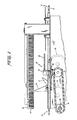
- Figures 3-8 are plan views in sequence illustrating the sequential carton turning according to the principles of the present invention.
- With reference now to Figures 1 and 2 of the drawings, a turning
apparatus 10 is illustrated incorporating the features of the present invention. The turningapparatus 10 is preferably positioned at the juncture or transition between the two conveyors, such as feed conveyors on a carton closing machine. The cartons move serially along the machine so as to pass various operating stations. For example, the cartons move past a filling station, flap folding stations, adhesive activation stations and then sealing stations for the flaps of the carton. Each carton is usually sealed on one side, the front, and then the carton is turned through 90° for simultaneous sealing of the two additional sides, that is the ends. The flaps are sealed by being plowed down in position by plow rails (not shown) to complete the closing of the carton. - The first in-line conveyor comprises an endless chain with
upstanding lugs 16 on the chain operative to engage and move the cartons along the predetermined feed path. The manner in which the cartons are fed by thefirst conveyor 12 is best illustrated by carton C, in Figure 3. Thepusher lug 16 of theconveyor 12 engages the trailing side of the carton C, under the trailing end flap. The carton C, has its longitudinal axis A, extending in the direction of the feed path (see Figure 3). - A second in-
line conveyor 20 is provided downstream of thefirst conveyor 12. A pair ofchains chain 14 has pushinglugs lug 27 lags behind thelug 25. For this reason, thelug 27 serves to complete the turning action of the cartons, as will be seen in more detail below. The early engagement of thelug 25 is provided by the upstream positioning of the sprocket carrying the chain 22 (see Figure 2). It should be understood that the twochains chain 14 so as to provide the proper feed and transition of the cartons along the feed path. The third carton positioned along the feed path in Figure 3 is carton C3. As shown, this carton has completed a full turn and thelugs - When the turning
apparatus 10 of the present invention is utilized in a carton closing environment, it is understood that the cartons arrive in the position of carton C, in Figure 3 with the front flap plowed down and sealed into position. Turning of the cartons through the progressive positions of cartons C, and C2 in Figures 3 to 8 to the final position of carton C3 is for the purpose of bringing the end flaps 53, 55 into proper position for sealing downstream (not shown). A new axis, A2, is then aligned with the feed path of the cartons through the end flap closing machine to effect the final closing of the cartons. - The main turning operation is provided in the preferred embodiment by a
friction plate 44 positioned at the transition area, as best shown in Figure 1. The bottom of the cartons first engage the friction plate at a point just upstream of the position of carton C, in Figure 3. A generallycoextensive brush 45 withbristles 47 is provided above the feed path in order to engage the tops of the cartons and thus urge the bottoms of the cartons against the plate. The bottom (and top) friction forces adjacent the side of each carton on the inside of the turn (as shown in Figure 3, the far side) serve to skew the carton into the turn. Theplate 44 may include strategically placed rubber strips 48 in order to provide increased friction in the area of initiation of the turn (see Figure 1). Of course, other main turning mechanism can be used in accordance with the broadest aspects of the present invention. - The turning assist concept of the present invention, preferably takes the form of a
turning assist mechanism 30 positioned along one side of the feed path for the cartons. The turningassist mechanism 30 comprises asweep finger 32 extending generally horizontally and radially outwardly from a mountinghub 34.Vertical drive shaft 36 serves to rotate thehub 34 and thus bodily move thefinger 32 so as to sweep across the feed path (see sequence Figures 3-8).Shaft 36 is driven synchronously with theconveyors chain 38 and adrive shaft 41. - Thus, in operation, and as best shown in the sequence Figures 3-8, the carton C, is transported to the turning station with
front side 51 adjacent guide rail 52 (see Figure 3). At this point, the front flap of the Charlotte-type carton has been folded down and sealed against the carton C1. The rotatingsweep finger 32 in the position shown in Figure 3 is not engaged with the carton C1. The far leading corner of the carton C, is in engagement with thefriction plate 44 and thebrush 45 is pressing the carton C, downwardly so that the carton's movement is just beginning to be retarded. - In Figure 4, the
finger 32 bodily moves from further rotation so that the distal end of thefinger 32 engages the side of the carton C, and positively initiates the turn. Thefinger 32 does, in effect, independently engage the side of carton C1, in turning. Thefinger 32 sweeps across the feed path of the carton. - The movement of the
finger 32 is horizontal and thus substantially parallel to the feed path. The timing is such that the finger engages thefront side 51 of the carton C, adjacent the leading edge of the carton (see Figure 4) for the most expeditious turning. - The sweeping of the
finger 32 continues through the sequence of Figures 5-7 where the maximum turning of the box occurs. At the point in Figure 8 of the drawing, the carton C1 completes the sweeping action, the completion of the turn is assured and thesweep finger 32 continues its movement in front of the carton. The finger comes around in a circle in readiness for engaging and turning the next-in-line carton, as shown by the position in Figure 3. - The carton C2 in Figure 3 is the carton positioned just downstream of the position of the carton C1 in Figure 8. At this point, the
lug 25 on the far side of the carton C2 is fully engaged with the new trailing side of the carton and thenear side lug 27 is being rotated into full pushing position (see Figure 2). The carton is also at this point being turned by the continued engagement of thefriction plate 44. During the next increments of movement of thelug 27 through Figures 5-8, the carton C2 reaches its full turned or reoriented position. - As best shown in the sequence Figures 3-8, the
finger 32 advantageously engages thefront side 51 of the carton adjacent the leading edge of the carton. This provides the most desirable turning leverage to the carton. Furthermore, once the distal end of the finger32 has engaged the side, the point of engagement remains substantially static. This provides maximum control over the turning operation and avoids scraping or marring the surface of the carton side. The point of engagement is preferably within 15-35% along the length of the carton. - The
finger 32 is preferably fabricated of a flexible rod in order to provide flexure as the rod engages the cartons. This prevents deleterious jolts to the carton, as can be experienced with prior art devices. - In view of the foregoing, the excellent results of utilizing the principles of turning a carton with positive assist can be realized. The turning is initiated positively by engagement of distal end of the
finger 32. The carton is assisted during substantially the full turn. This carton assist is especially useful for turning cartons having an elongated shape, as the cartons illustrated in the figures, and for turning cartons that are unusually heavy, orwith contents susceptible to shifting. The device is simple in construction and utilizes driving means directly engaged with the closing machine drive. The positive control given by the sweeping action of the finger eliminates any erratic turning action that might otherwise occur with the cartons. - While the carton turning apparatus of the present invention has been described in considerable detail in the best mode for carrying out the invention, it is understood that various changes and modifications may occur to persons of ordinary skill in the art without departing from the scope of the appended claims.
Claims (14)
Applications Claiming Priority (2)
| Application Number | Priority Date | Filing Date | Title |
|---|---|---|---|
| US300601 | 1981-09-09 | ||
| US06/300,601 US4476972A (en) | 1981-09-09 | 1981-09-09 | Method and apparatus for turning filled cartons with positive assist |
Publications (3)
| Publication Number | Publication Date |
|---|---|
| EP0074129A2 EP0074129A2 (en) | 1983-03-16 |
| EP0074129A3 EP0074129A3 (en) | 1983-06-08 |
| EP0074129B1 true EP0074129B1 (en) | 1986-09-03 |
Family
ID=23159789
Family Applications (1)
| Application Number | Title | Priority Date | Filing Date |
|---|---|---|---|
| EP82200946A Expired EP0074129B1 (en) | 1981-09-09 | 1982-07-23 | Method and apparatus for turning filled cartons with positive assist |
Country Status (4)
| Country | Link |
|---|---|
| US (1) | US4476972A (en) |
| EP (1) | EP0074129B1 (en) |
| CA (1) | CA1185278A (en) |
| DE (1) | DE3273026D1 (en) |
Families Citing this family (5)
| Publication number | Priority date | Publication date | Assignee | Title |
|---|---|---|---|---|
| GB8826962D0 (en) * | 1988-11-18 | 1988-12-21 | Metal Box Plc | Method & apparatus for closing cartons |
| US5660262A (en) * | 1995-01-13 | 1997-08-26 | Kliklok Corporation | High speed carton feeding/turning system |
| DE19906882C2 (en) | 1999-02-19 | 2001-01-25 | Seidel Helmut | Method and device for rotating an object, in particular for rotating a cuboid folding box |
| US7712599B1 (en) | 2006-11-21 | 2010-05-11 | Kliklok Corporation | In-line carton feeding and forming machine with carton lug conveyor and related methods |
| FR2959989B1 (en) | 2010-05-11 | 2012-05-11 | Sidel Participations | DEVICE FOR ORIENTING OBJECTS AND INSTALLATION COMPRISING SUCH A DEVICE. |
Family Cites Families (15)
| Publication number | Priority date | Publication date | Assignee | Title |
|---|---|---|---|---|
| DE926776C (en) * | 1953-03-06 | 1955-04-25 | Jagenberg Werke Ag | Device for turning containers, packs or the like. |
| US2709513A (en) * | 1954-03-04 | 1955-05-31 | Oswego Falls Corp | Apparatus for rearranging containers |
| US2805753A (en) * | 1955-01-19 | 1957-09-10 | Oswego Falls Corp | Container handling apparatus |
| US2984332A (en) * | 1959-12-29 | 1961-05-16 | Baljak Corp | Method of and device for pivoting articles |
| US3142371A (en) * | 1960-02-19 | 1964-07-28 | Burton Machine Corp John | Spotting device for bottles and the like |
| US3165193A (en) * | 1962-07-20 | 1965-01-12 | Fmc Corp | Article handling apparatus |
| DE1511572A1 (en) * | 1966-05-12 | 1969-10-02 | Eickhoff Geb | Device for turning a cube or square box |
| US3427779A (en) * | 1967-06-15 | 1969-02-18 | Colonial Beverage Equipment | Apparatus for packaging articles |
| US3619977A (en) * | 1970-03-10 | 1971-11-16 | Fibreboard Corp | Apparatus and method for heat sealing cartons |
| GB1292378A (en) * | 1970-03-18 | 1972-10-11 | Mead Corp | Conveyor system |
| US4010842A (en) * | 1973-10-18 | 1977-03-08 | Atlas Pacific Engineering Company | Machine for orienting pears |
| US4086744A (en) * | 1974-04-17 | 1978-05-02 | G. D. Societa Per Azioni | Device for preparing hinge-lid packets of cigarettes for application of sealing strips and the like |
| US3958688A (en) * | 1974-09-23 | 1976-05-25 | Pneumatic Scale Corporation | Container turner |
| US4020941A (en) * | 1975-10-28 | 1977-05-03 | Simplimatic Engineering Co. | Article inverter |
| GB1585324A (en) * | 1978-05-30 | 1981-02-25 | Potter Electrical Services Ltd | Egg conveyors |
-
1981
- 1981-09-09 US US06/300,601 patent/US4476972A/en not_active Expired - Lifetime
-
1982
- 1982-05-28 CA CA000403971A patent/CA1185278A/en not_active Expired
- 1982-07-23 EP EP82200946A patent/EP0074129B1/en not_active Expired
- 1982-07-23 DE DE8282200946T patent/DE3273026D1/en not_active Expired
Also Published As
| Publication number | Publication date |
|---|---|
| US4476972A (en) | 1984-10-16 |
| EP0074129A2 (en) | 1983-03-16 |
| CA1185278A (en) | 1985-04-09 |
| EP0074129A3 (en) | 1983-06-08 |
| DE3273026D1 (en) | 1986-10-09 |
Similar Documents
| Publication | Publication Date | Title |
|---|---|---|
| US3555776A (en) | Machine for forming a tray around a group of articles | |
| US3956868A (en) | Carton opening, filling and closing apparatus | |
| US7695421B2 (en) | Rotary carton feeder | |
| US5531661A (en) | Carrier sleeve erecting apparatus and method | |
| US4685275A (en) | Carton opening apparatus | |
| US4215525A (en) | Tray forming machine | |
| US4802324A (en) | Vertical cartoning assembly and method | |
| US2890560A (en) | Case flap opener | |
| US3058271A (en) | Carton feeding, erecting, filling and closing mechanism | |
| US4562687A (en) | Tray carton end panel folding and sealing assembly | |
| US4590745A (en) | Carton closing machine | |
| GB2150906A (en) | Packaging machine | |
| US4476972A (en) | Method and apparatus for turning filled cartons with positive assist | |
| FI84457B (en) | VIKNINGSMEKANISM FOER DAMMFLIK FOER ANVAENDNING VID UTFORMNING AV BAERFOERPACKNINGAR AV OMSLAGSTYP. | |
| US4159610A (en) | Closure mechanism for closing end of loaded cartons | |
| US4705159A (en) | Conveying system for removing containers from a packaging machine | |
| EP0369777B1 (en) | Method and apparatus for rotating cartons | |
| US4012998A (en) | Carton sealing method and apparatus | |
| US2440120A (en) | Folding box machine | |
| GB2096093A (en) | Box flap sealing apparatus | |
| US2579803A (en) | Case sealing machine | |
| US2815140A (en) | Carton unloader | |
| US4015403A (en) | Wrap-around carton forming machine | |
| US4012999A (en) | Apparatus for forming trays | |
| US2828595A (en) | Package handling apparatus |
Legal Events
| Date | Code | Title | Description |
|---|---|---|---|
| PUAI | Public reference made under article 153(3) epc to a published international application that has entered the european phase |
Free format text: ORIGINAL CODE: 0009012 |
|
| AK | Designated contracting states |
Designated state(s): DE FR GB IT |
|
| PUAL | Search report despatched |
Free format text: ORIGINAL CODE: 0009013 |
|
| AK | Designated contracting states |
Designated state(s): DE FR GB IT |
|
| 17P | Request for examination filed |
Effective date: 19830526 |
|
| ITF | It: translation for a ep patent filed | ||
| GRAA | (expected) grant |
Free format text: ORIGINAL CODE: 0009210 |
|
| AK | Designated contracting states |
Kind code of ref document: B1 Designated state(s): DE FR GB IT |
|
| REF | Corresponds to: |
Ref document number: 3273026 Country of ref document: DE Date of ref document: 19861009 |
|
| ET | Fr: translation filed | ||
| PLBE | No opposition filed within time limit |
Free format text: ORIGINAL CODE: 0009261 |
|
| STAA | Information on the status of an ep patent application or granted ep patent |
Free format text: STATUS: NO OPPOSITION FILED WITHIN TIME LIMIT |
|
| 26N | No opposition filed | ||
| ITTA | It: last paid annual fee | ||
| PGFP | Annual fee paid to national office [announced via postgrant information from national office to epo] |
Ref country code: FR Payment date: 19980611 Year of fee payment: 17 |
|
| PGFP | Annual fee paid to national office [announced via postgrant information from national office to epo] |
Ref country code: GB Payment date: 19990618 Year of fee payment: 18 |
|
| PG25 | Lapsed in a contracting state [announced via postgrant information from national office to epo] |
Ref country code: FR Free format text: THE PATENT HAS BEEN ANNULLED BY A DECISION OF A NATIONAL AUTHORITY Effective date: 19990731 |
|
| PGFP | Annual fee paid to national office [announced via postgrant information from national office to epo] |
Ref country code: DE Payment date: 20000629 Year of fee payment: 19 |
|
| REG | Reference to a national code |
Ref country code: FR Ref legal event code: ST |
|
| PG25 | Lapsed in a contracting state [announced via postgrant information from national office to epo] |
Ref country code: GB Free format text: LAPSE BECAUSE OF NON-PAYMENT OF DUE FEES Effective date: 20000723 |
|
| GBPC | Gb: european patent ceased through non-payment of renewal fee |
Effective date: 20000723 |
|
| PG25 | Lapsed in a contracting state [announced via postgrant information from national office to epo] |
Ref country code: DE Free format text: LAPSE BECAUSE OF NON-PAYMENT OF DUE FEES Effective date: 20020501 |