EP0074015B1 - Remotely actuated rearview mirror for automotive vehicles - Google Patents
Remotely actuated rearview mirror for automotive vehicles Download PDFInfo
- Publication number
- EP0074015B1 EP0074015B1 EP82107757A EP82107757A EP0074015B1 EP 0074015 B1 EP0074015 B1 EP 0074015B1 EP 82107757 A EP82107757 A EP 82107757A EP 82107757 A EP82107757 A EP 82107757A EP 0074015 B1 EP0074015 B1 EP 0074015B1
- Authority
- EP
- European Patent Office
- Prior art keywords
- motor
- mirror
- reflective
- housing
- switch
- Prior art date
- Legal status (The legal status is an assumption and is not a legal conclusion. Google has not performed a legal analysis and makes no representation as to the accuracy of the status listed.)
- Expired
Links
Images


Classifications
-
- B—PERFORMING OPERATIONS; TRANSPORTING
- B60—VEHICLES IN GENERAL
- B60R—VEHICLES, VEHICLE FITTINGS, OR VEHICLE PARTS, NOT OTHERWISE PROVIDED FOR
- B60R1/00—Optical viewing arrangements; Real-time viewing arrangements for drivers or passengers using optical image capturing systems, e.g. cameras or video systems specially adapted for use in or on vehicles
- B60R1/02—Rear-view mirror arrangements
- B60R1/08—Rear-view mirror arrangements involving special optical features, e.g. avoiding blind spots, e.g. convex mirrors; Side-by-side associations of rear-view and other mirrors
- B60R1/083—Anti-glare mirrors, e.g. "day-night" mirrors
- B60R1/086—Anti-glare mirrors, e.g. "day-night" mirrors using a mirror angularly movable between a position of use and a non-glare position reflecting a dark field to the user, e.g. situated behind a transparent glass used as low-reflecting surface; Wedge-shaped mirrors
- B60R1/087—Anti-glare mirrors, e.g. "day-night" mirrors using a mirror angularly movable between a position of use and a non-glare position reflecting a dark field to the user, e.g. situated behind a transparent glass used as low-reflecting surface; Wedge-shaped mirrors with remote or automatic control means
Landscapes
- Engineering & Computer Science (AREA)
- Multimedia (AREA)
- Mechanical Engineering (AREA)
- Rear-View Mirror Devices That Are Mounted On The Exterior Of The Vehicle (AREA)
- Optical Elements Other Than Lenses (AREA)
Description
- This invention relates to rearview mirrors for automotive vehicles and, more particularly, to an improved inside rearview mirror which is particularly adapted for use with automotive vehicles and which may be very conveniently indexed, by the driver of such a vehicle, from a full reflectance mode (day) to a partial reflectance mode (night) for glare protection from light emanating from the headlights of vehicles approaching from the rear. Rearview mirrors embodying the present invention incorporate a prism type reflective element which is substantially identical to the prism type reflective elements utilized in lever operated day-night mirrors conventionally provided on modern day automobiles. As is well known in the art, the driver of a vehicle equipped with such a lever operated mirror may adjust the mirror to a full reflectance mode or a partial reflectance mode by turning or flipping a lever located on the base of the mirror. However, such prior lever operated mirrors are often not used by numerous drivers because of the inconvenience involved in reaching up to the mirror to make the desired adjustment. In general, rearview mirrors embodying the present invention may be conveniently indexed to the alternate reflective mode each time that an electrical switch button is depressed by the driver of the vehicle, the switch button being positioned in a convenient location such as on or near the steering wheel of the vehicle. The power required to index the reflective element of the mirror is drawn either from the vehicle's electrical system or from a self contained battery.
- Heretofore, automatic mirrors have also been devised for the purpose of automatically shifting the reflective element incorporated therein between the full reflectance and partial reflectance modes without requiring any action on the part of the driver of the vehicle. However, prior automatic mirrors of the indicated character are relatively expensive as compared with mirrors embodying the present invention, and many prior automatic mirrors have deficiencies (such as, for example, noisy operating characteristics, excessive vibration characteristics, high electrical current requirements, ungainly connections, poor clarity, poor performance characteristics at low operating temperatures, and slow operating times) that preclude practical operation of the devices with the result that lever operated mirrors of the type mentioned hereinabove are still normally provided as part of the original equipment of automotive vehicles manufactured throughout the world. Examples of these automatic mirrors are disclosed in German Utility Model 7319284 and U.S. Patent 3,722,984.
- An object of the present invention is to overcome the aforementioned as well as other disadvantages in prior automotive vehicle mirrors of the indicated character and to provide an improved remotely actuated rearview mirror for automotive vehicles incorporating improved means for indexing a reflective element, incorporated in the mirror successively between a full reflectance mode and a partial reflectance mode through the agency of electrical switch means positioned for easy accessibility by the driver of a vehicle.
- Another object of the present invention is to provide an improved remotely actuated rearview mirror incorporating improved means whereby an indexing cycle of a reflective element incorporated therein is initiated by momentary closure of electrical switch means and once initiated, the indexing cycle is completed.
- According to the invention there is provided a remotely actuated rearview mirror for an automotive vehicle, including a reflective means having a full reflectance mode and a partial reflectance mode and means controlled by a manually actuatable switch for moving said reflective prism between said full reflectance and partial reflectance modes, characterized in that said reflective means is a prism and in that said moving means comprises a unidirectional DC motor for indexing said reflective prism successively between its two modes and that an additional switch is provided for de-energizing said DC motor when the reflective prism is in each of its reflective modes.
- Figure 1 is a perspective view of a remotely actuated rearview mirror embodying the present invention, showing the same installed on the windshield of a vehicle and also illustrating a steering wheel with an electrical switch mounted thereon for controlling the reflective state of the mirror;
- Figure 2 is an elevational view, with portions broken away, of the mirror illustrated in Figure 1 as it faces the rear of the vehicle;
- Figure 3 is an elevational view of a portion of the mirror illustrated in Figure 1 as it faces the front of the vehicle, showing the same with the housing removed for clarity of illustration;
- Figure 4 is a cross sectional view of a portion of the structure illustrated in Figure 3, taken on the line 4-4 thereof;
- Figure 5 is a cross sectional view of a portion of the structure illustrated in Figure 3, taken on the line 5-5 thereof;
- Figure 6 is a cross sectional view of a portion of the structure illustrated in Figure 3, taken on the line 6-6 thereof;
- Figure 7 is a cross sectional view of a portion of the structure illustrated in Figure 3, taken on the line 7-7 thereof;
- Figure 8 is a schematic exploded view of certain of the components of the mirror illustrated in Figure 1; and
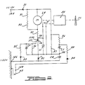
- Figure 9 is a schematic electrical diagram of the mirror control circuitry embodying the present invention.
- Referring to the drawings, a preferred embodiment of the invention is illustrated therein and is comprised of a remotely actuated rearview mirror, generally designated 20, which is adapted to be mounted on the inside of the
windshield 22 of an automotive vehicle through the agency of aconventional mounting member 24 incorporating conventional ball and socket means (not shown) permitting angular adjustment of the mirror in a conventional manner. The outer end portion 26 of themounting member 24 is fixed, for example by an adhesive, to thewindshield 22 while the inner end portion of the mounting member is provided with anon-circular mounting block 28 adapted to be received in a similarly shapedhole 30 provided in abase 32, thebase 32 being retained by ascrew 34. In the preferred embodiment illustrated, the remotely actuatedrearview mirror 20 includes a conventional prism typereflective element 36 which is mounted on ahousing 38, the housing having top andbottom walls 40 and 42 integrally joined by side walls 44 and 46 and arear wall 48 to define a chamber 50 which is open in the direction facing the rear of the vehicle. The prism typereflective element 36 is retained by a grommet 52 fitted over the free edge of the top, bottom and side walls of the housing whereby thereflective element 36 is permanently fixed to thehousing 38. Thehousing 38, in turn, is pivotally connected to thebase 32 through the agency of axially alignedtrunnions flanges base 32, thetrunnions bearings reflective element 36 and thehousing 38 may be pivoted as a unit relative to thebase 32, the central portion of themounting member 24 passing through an opening 66 provided in therear wall 48 of the housing with sufficient clearance to permit the pivotal movement of the reflective element and the housing relative to themounting member 24 whereby the reflective element may be moved from a full reflective mode to a partial reflective mode and thereafter returned to the full reflective mode by pivoting the reflective element and the housing as a unit about the aligned longitudinal axis of thetrunnions - In the embodiment of the invention illustrated, a small,
unidirectional DC motor 68 is provided as the prime mover for moving thereflective element 36 and thehousing 38 between the full reflectance and partial reflectance positions. Themotor 68 includes ahousing 69 which is mounted on thebase 32 through the agency of amounting bracket 70 that includes a pair of L-shaped leg portions front wall 74 of the motor housing, and anintegral base portion 76 which engages therear wall 78 of the motor housing. Thebottom wall 79 of themotor housing 69 is supported by an outwardly projectingflange 96 which is formed as an integral part of thebase 32. Themounting bracket 70 also carrieselectrical connectors 80 and 82 which make electrical contact with the motor, and theelectrical connectors 80 and 82 are soldered to a printedcircuit board 136 which is fixed to thebase 32, as withscrews circuit board 136 being disposed within the chamber 50 defined by the housing and carrying various components and electrical conductor paths of the control circuitry embodying the invention. The solder connection provides both an electrical connection 'to the printed circuit board and a mechanical support for themounting bracket 70. Thus, themounting bracket 70 and the electrical connectors carried thereby make the necessary electrical connections to themotor 68 and also aid in the support and retention of the motor. - A three stage speed reduction, generally designated 84, is provided for the
motor 68, such speed reduction being comprised of adrive pulley 86 which is fixed to the drive shaft 88 of themotor 68. By means of an O-ring belt 90, thedrive pulley 86 drives a pulley 92 carried by ashaft 94 supported by outwardly projectingflanges base 32, theshaft 94 also carrying apulley 100 which by means of an 0-ring belt 102 drives anintegral pulley 104 and apinion 110 carried by ashaft 106 also supported by theflanges shafts snap rings 108. Thepinion 110 drives aspur gear 112 mounted on theshaft 94. Integral with thespur gear 112 are aswitch cam 118 and aneccentric cam 120 disposed in apassageway 122 defined by theweb portion 124 of a generally channel shapedbridge member 126. Thebridge member 126 includes aflange portion 128 which is held against theinside surface 130 of thereflective element 36. Thebridge member 126 also includes aflange portion 132 which is fixed to thewall 48 through the agency of ascrew 134. With such a construction, rotation of theeccentric cam 120 causes theeccentric bridge 126 to translate thereby pivoting thereflective element 36 and thehousing 38 as a unit about the aligned axes of thetrunnions reflective element 36 between the full reflectance and partial reflectance modes. Theswitch cam 118 functions to close and open the contacts of the limit switch K1 to energize and de-energize the motor as will be described hereinafter in greater detail, the contacts of the limit switch K1 being open in both the full reflectance position and the partial reflectance position of thereflective element 36 and closed when the reflective element is intermediate such positions. - In the embodiment of the invention illustrated, a manually actuatable electrical switch K2 is provided which is mounted on the
steering wheel 142 of the vehicle and positioned for convenient actuation by the driver of the vehicle, the switch K2 being electrically connected by any suitable electrical conductors in the mirror control circuitry illustrated in Figure 9. While the switch K2 is illustrated as being in the form of a push button switch, it will be understood that other forms of manually actuatable switches may be utilized. It will also be understood that the switch K2 may be mounted in any other position conveniently accessible to the driver, as for example, the switch K2 may be mounted on the turn signal lever TSL, on the tilt-wheel lever TWL, on the dashboard DB or in any other position convenient for the driver. Rotation of the unidirectionally drivenDC motor 68 is initiated by a momentary closing of the switch K2 whenever a change in reflective state is required. Circuit action is such that an indexing cycle is initiated by a very short closure of the switch K2, and once initiated, the indexing cycle is completed. Sustained closure of the switch K2 results in only one indexing step, and the switch K2 must be opened and closed again to index another step. - Referring to Figure 9, the circuitry embodying the present invention is illustrated therein. As shown in Figure 9, the circuit is energized by a positive voltage at the
terminal 144, which voltage may be supplied by the vehicle electrical system or by a self-contained battery. Theterminal 146 is connected to the electrical system ground such as the vehicle chassis. Theterminal 148 is the control. input which is momentarily connected to ground through the switch K2 to initiate a change to the alternate reflective state. The circuitry also includes theunidirectional DC motor 68, the switches K1 and K2, diodes D1, D2, D3 and D4, a silicon controlled rectifier SCR1, capacitors C1 through C4 and resistors R1 through R8, such components all being electrically connected by suitable conductors as illustrated in the drawings and as will be described hereinafter in greater detail. - As previously mentioned, the
unidirectional DC Motor 68 rotates theeccentric cam 120 through the threestage speed reduction 84 to move thereflective element 36 between its reflective positions. The contacts of the switch K1 are closed except when thereflective element 36 is in each of its two stable positions. The contacts of the switch K1 open and de-energize themotor 68 when the reflective element is positioned in its desired reflective state. - The diodes D1 and D4 prevent damage to the circuit due to the incorrect wiring. The resistors R1 and R2 conduct current generated by the
motor 68 when it is de-energized and still coasting. This provides braking action to prevent thereflective element 36 from coasting on through its stop positions and continuing to oscillate under high supply voltage conditions. The current conducted by the resistors R1 and R2 while the silicon controlled rectifier SCR1 is conducting prevents turn-off of the silicon controlled rectifier. Such turn-off may otherwise occur due to an interruption of the motor current caused by faulty brush contact in themotor 68. The resistors R1 and R2 are preferably widely spaced and, in the embodiment of the invention illustrated, are used in place of one resistor to distribute the heat they dissipate. This prevents damage from heat generated in the event that the resistors R1 and R2 remain energized due to a fault condition. The resistors R1 and R2 are also preferably made of a high temperature coefficient wire so that their resistance increases and limits heating under the fault condition mentioned hereinabove. - The capacitor C3 is charged through the resistor R6, and the diode D2 is forward biased by current through the resistor R7. The capacitor C1 limits rapid voltage excursions at the
anode 150 of the silicon controlled rectifier SCR1 to prevent unwanted turn-on of the silicon controlled rectifier. The resistor R4 prevents turn-on of the silicon controlled rectifier due to leakage current at itsgate 152. The capacitor C2 prevents turn-on of the silicon controlled rectifier due to interference generated transient voltages at the gate. The diode D3 adds to the turn-on noise margin of the silicon controlled rectifier and prevents sinking of gate' current through the resistor R5 and a possibility of a resulting gate turn-off of the silicon controlled rectifier. The resistor R3 limits motor current. - The switch K1 is actuated by the
cam 118 in the gear reduction unit, the switch K1 being open when thereflective element 36 is in each of its stable positions. The switch K1 closes during the traverse of the unit between each of its stable positions. Closure of the switch K1 shorts the silicon controlled rectifier allowing the silicon controlled rectifier to turn-off, and the switch K1 continues to energize themotor 68 until thereflective element 36 has indexed to its next stable position at which point thecam 118 opens the switch K1 and thereflective element 36 comes to rest. - In the operation of the motor control circuit, closure of the switch K2 discharges the capacitor C3 through the resistor R8 and the diode D4. The capacitor C4 receives negative charge from the capacitor C3 at the terminal 154 which goes negative. The diode D2 is reverse biased and the cathode 156 of the silicon controlled rectifier goes negative thereby forward biasing the diode D3 and causing gate current to flow through the diode D3 and the resistor R5 into the
gate terminal 152 of the silicon controlled rectifier. The silicon controlled rectifier then turns on and energizes themotor 68 through the resistor R3. Thecam 118 in the gear reduction unit closes the switch K1 and the silicon controlled rectifier is turned off. Thereflective element 36 is then carried to its next stable position as previously mentioned. Discharge of the capacitor C3 is rapid and the switch K2 must be opened to allow the capacitor C3 to recharge through the resistor R6 before another cycle can be initiated. After turn-on of the silicon controlled rectifier, the capacitor C4 charges rapidly and the diode D2 conducts the motor current. - Typical values for the components of the circuitry described hereinabove are as follows:


- In the operation of the
mirror 20, upon entering the vehicle, the driver should adjust thereflective element 36 for good rearward vision. If the headlights of a vehicle approaching from the rear tend to cause annoying glare, the driver may momentarily close the switch K2 to initiate movement of thereflective element 36 to the antiglare position and the following chain of events will take place. Themotor 68 is energized and begins rotating to drive the threestage speed reduction 84 to rotate theeccentric cam 120 which causes theeccentric bridge 126 to translate, thereby moving thereflective element 36 and themirror housing 38 as a unit to the antiglare position. The contacts of the switch K1 open and de-energize themotor 68 when thereflective element 36 is positioned in the desired antiglare position. Thereflective element 36 is then held securely in the antiglare position until the source of the glare is removed. When the source of the glare is removed, the driver may again momentarily close the switch K2 to signal themotor 68 to reinitiate rotation, again driving the threestage speed reduction 84 to cause theswitch cam 118 and theeccentric cam 120 to rotate, thereby closing the limit switch K1 and also moving thereflective element 36 through the agency of the eccentric bridge to return the reflective element to the full reflective mode. At this point, the limit switch K1 opens and the cycle is completed. Thereflective element 36 will then be held securely in the full reflectance mode until another source of annoying glare is encountered, whereupon the driver may cause the cycle to be repeated. - From the foregoing it will be appreciated that with the present invention, a small, very low cost unidirectional DC motor is utilized as the prime mover for the reflectance element. The use of a unidirectional DC motor driving through a combination belt drive and gear drive system makes it possible to have high force available to move the reflectance element because several revolutions of the motor can be utilized to do the work. The small motor that can be utilized is significantly lighter in weight than a solenoid. Moreover, the small motor and drive train embodying the present invention allows the total mirror package to be similar to a standard day-night mirror in overall size. Because of the high force available, the reflective element can be permanently fixed to the mirror housing and the reflective element and the housing moved as a unit to shift from a full reflectance mode to a partial reflectance mode and back again whereby a distinct advantage in controlling vibrations is obtained. Moreover, no return spring system is required, so the entire system is tight and free of extraneous movement which would contribute to vibration problems. The belt drive in the first two stages of the
speed reduction unit 84 acts to silence the operation of themirror 20, thereby making it quieter than solenoid operated devices. (It is preferred that the O-rings in the first two stages of thespeed reduction unit 84 be made of silicone rubber since such rubber is resistant to high temperatures and retains its flexibility at very low temperatures). The third stage of thespeed reduction unit 84 is a low cost pinion and spur gear arrangement with the result that the speed reduction system is very quiet and can be produced at low cost. - The switch K2 provides a single pole momentary contact to ground and the circuitry embodying the present invention accommodates this mode of switch action so that the switching function is accomplished through a single control line to the mirror. Circuit action is such that an indexing cycle is initiated by a very short closure of the switch, and once initiated, the indexing cycle is completed. Circuit operation is not initiated by any normal capacitance or radio frequency coupling to the control line or to the mirror circuit, and lines to the mirror may be routed normally with no special shielding requirements. Moreover, the circuit components are low in cost and yet are able to withstand the severe electrical and physical environments encountered in automotive vehicles.
- The mounting of -the reflective element permanently on the mirror housing and moving the reflective element and the housing as a unit reduces vibration to a minimum, and the reflective element and the housing are firmly held in both the full reflectance and partial reflectance positions. The limit switch K1 that controls the end positions of the mirror cycle is operated from the
switch cam 118 so that the final positions are closely controlled.
Claims (9)
Applications Claiming Priority (2)
| Application Number | Priority Date | Filing Date | Title |
|---|---|---|---|
| US299104 | 1981-09-03 | ||
| US06/299,104 US4488777A (en) | 1981-09-03 | 1981-09-03 | Remotely actuated rearview mirror for automotive vehicles |
Publications (2)
| Publication Number | Publication Date |
|---|---|
| EP0074015A1 EP0074015A1 (en) | 1983-03-16 |
| EP0074015B1 true EP0074015B1 (en) | 1987-01-21 |
Family
ID=23153325
Family Applications (1)
| Application Number | Title | Priority Date | Filing Date |
|---|---|---|---|
| EP82107757A Expired EP0074015B1 (en) | 1981-09-03 | 1982-08-24 | Remotely actuated rearview mirror for automotive vehicles |
Country Status (6)
| Country | Link |
|---|---|
| US (1) | US4488777A (en) |
| EP (1) | EP0074015B1 (en) |
| JP (1) | JPS5853536A (en) |
| AU (1) | AU566665B2 (en) |
| CA (1) | CA1187318A (en) |
| DE (1) | DE3275172D1 (en) |
Families Citing this family (24)
| Publication number | Priority date | Publication date | Assignee | Title |
|---|---|---|---|---|
| WO1986005148A1 (en) * | 1985-03-08 | 1986-09-12 | Miroslaw Janowicz | Motor vehicle with changeable exterior mirror |
| DE3565382D1 (en) * | 1985-07-10 | 1988-11-10 | Hohe Kg | Anti-glare interior vehicle mirror with electro-optical control |
| USD300312S (en) | 1986-02-27 | 1989-03-21 | Donnelly Corporation | Combined rearview mirror and light unit |
| US4828361A (en) * | 1987-08-26 | 1989-05-09 | Siegel-Robert, Inc. | Semi-automatic rear view mirror assembly |
| US4948242A (en) * | 1988-03-22 | 1990-08-14 | Donnelly Mirrors Limited | Vehicle rearview mirror assembly |
| US4906089A (en) * | 1988-07-28 | 1990-03-06 | Giovanni Biondi | Automotive tilt mirror |
| US5475366A (en) * | 1988-12-05 | 1995-12-12 | Prince Corporation | Electrical control system for vehicle options |
| US5614885A (en) * | 1988-12-05 | 1997-03-25 | Prince Corporation | Electrical control system for vehicle options |
| US5223814A (en) * | 1988-12-05 | 1993-06-29 | Prince Corporation | Sensor for vehicle accessories |
| US5818636A (en) * | 1990-02-26 | 1998-10-06 | Molecular Displays, Inc. | Complementary surface confined polmer electrochromic materials, systems, and methods of fabrication therefor |
| US5457564A (en) * | 1990-02-26 | 1995-10-10 | Molecular Displays, Inc. | Complementary surface confined polymer electrochromic materials, systems, and methods of fabrication therefor |
| US5122647A (en) * | 1990-08-10 | 1992-06-16 | Donnelly Corporation | Vehicular mirror system with remotely actuated continuously variable reflectance mirrors |
| USD351370S (en) | 1993-03-18 | 1994-10-11 | Donnelly Mirrors Limited | Rearview mirror |
| EP0615882A3 (en) * | 1993-03-19 | 1994-11-02 | Donnelly Mirrors Ltd | Rearview mirror assembly. |
| US5521744A (en) * | 1993-12-02 | 1996-05-28 | Mirror Systems, Inc. | Dimmable safety mirror suitable for motor vehicles and method of operation |
| US5820245A (en) * | 1995-12-11 | 1998-10-13 | Donnelly Corporation | Rearview mirror assembly |
| USD400481S (en) | 1995-12-11 | 1998-11-03 | Donnelly Corporation | Rearview mirror |
| US6000823A (en) | 1995-12-11 | 1999-12-14 | Donnelly Mirrors Limited | Rearview mirror assembly |
| USD391214S (en) | 1997-01-28 | 1998-02-24 | Donnelly Corporation | Rearview mirror assembly |
| US5969870A (en) * | 1997-09-18 | 1999-10-19 | Anvik Corporation | Remotely adjustable, anti-glare vehicle mirror system |
| DE102007017170A1 (en) * | 2007-04-12 | 2008-10-16 | GM Global Technology Operations, Inc., Detroit | Self-dimming mirror in a motor vehicle |
| US20110051268A1 (en) * | 2009-09-03 | 2011-03-03 | Patrick Martin | Blind spot mirror |
| US8545647B2 (en) * | 2009-11-19 | 2013-10-01 | Pilkington Group Limited | Item of hardware and method of making and bonding same |
| EP3219549A1 (en) * | 2016-03-14 | 2017-09-20 | Ficomirrors, S.A.U. | Mirror assembly for a vehicle |
Family Cites Families (8)
| Publication number | Priority date | Publication date | Assignee | Title |
|---|---|---|---|---|
| US2806408A (en) * | 1956-10-11 | 1957-09-17 | Moeller John | Electrically operated rear view mirror |
| US3059539A (en) * | 1959-02-04 | 1962-10-23 | Standard Mirror Co Inc | Multi-position rear vision mirror |
| US3680951A (en) * | 1970-04-01 | 1972-08-01 | Baldwin Co D H | Photoelectrically-controlled rear-view mirrow |
| US3722984A (en) * | 1971-06-29 | 1973-03-27 | Baldwin Co D H | Day-night mirror for vehicles |
| DE7319284U (en) * | 1972-05-26 | 1973-08-30 | Zizala K Metallwarenfabriken | Dimming rearview mirror |
| JPS5172043A (en) * | 1974-12-18 | 1976-06-22 | Kito Kk | BUNKATSUGATAROODOSHIIBUOJUSURU DORYOKU DENTATSUSOCHI |
| JPS582009B2 (en) * | 1976-07-02 | 1983-01-13 | 川崎重工業株式会社 | Shaving cutter for gears |
| US4256375A (en) * | 1979-02-26 | 1981-03-17 | Parker-Hannifin Corporation | Remote controllable motorized rear view mirror |
-
1981
- 1981-09-03 US US06/299,104 patent/US4488777A/en not_active Expired - Fee Related
-
1982
- 1982-08-18 CA CA000409652A patent/CA1187318A/en not_active Expired
- 1982-08-24 EP EP82107757A patent/EP0074015B1/en not_active Expired
- 1982-08-24 DE DE8282107757T patent/DE3275172D1/en not_active Expired
- 1982-09-03 JP JP57153813A patent/JPS5853536A/en active Pending
-
1983
- 1983-05-16 AU AU14577/83A patent/AU566665B2/en not_active Ceased
Also Published As
| Publication number | Publication date |
|---|---|
| AU1457783A (en) | 1984-11-22 |
| AU566665B2 (en) | 1987-10-29 |
| US4488777A (en) | 1984-12-18 |
| EP0074015A1 (en) | 1983-03-16 |
| DE3275172D1 (en) | 1987-02-26 |
| CA1187318A (en) | 1985-05-21 |
| JPS5853536A (en) | 1983-03-30 |
Similar Documents
| Publication | Publication Date | Title |
|---|---|---|
| US4488777A (en) | Remotely actuated rearview mirror for automotive vehicles | |
| EP0067335B1 (en) | Automatic rearview mirror for automotive vehicles | |
| US4948242A (en) | Vehicle rearview mirror assembly | |
| US4847737A (en) | Vehicle vanity with light control | |
| CA1200998A (en) | Remotely actuated rearview mirror for automotive vehicles | |
| US4015137A (en) | Control for activating motor vehicle electrical load | |
| JPH01283701A (en) | Inclinating device of head lamp for vehicle | |
| KR100329668B1 (en) | Optical axis control system for automobile head-lamp | |
| EP0367668B1 (en) | Position command device for a movable member in a number of discrete positions, especially for tilting the headlight of a car | |
| US20040208015A1 (en) | Vehicle mirror with internal illumination source and transmitting housing | |
| JP2691731B2 (en) | Control device for automobile main light circuit | |
| JP3424508B2 (en) | Optical axis adjustment drive unit of headlight optical axis adjustment device | |
| US4011460A (en) | Control for activating motor vehicle electrical load | |
| GB2076763A (en) | Pivotable Vehicle Rear View Mirror | |
| JPH0121059Y2 (en) | ||
| JPS6322745A (en) | Internal back mirror for automobile | |
| EP0584942A2 (en) | Headlamp levelling system | |
| JPH07242146A (en) | Lighting dimmer | |
| KR0153149B1 (en) | Car fog lights | |
| JPH0236235Y2 (en) | ||
| JPH0115544Y2 (en) | ||
| JPH0114514Y2 (en) | ||
| JPH0343063Y2 (en) | ||
| KR910006271Y1 (en) | Flasher of car headlight | |
| JPH01503618A (en) | A device that pivots a car mirror from its normal position to a non-dazzling position. |
Legal Events
| Date | Code | Title | Description |
|---|---|---|---|
| PUAI | Public reference made under article 153(3) epc to a published international application that has entered the european phase |
Free format text: ORIGINAL CODE: 0009012 |
|
| AK | Designated contracting states |
Designated state(s): DE FR GB |
|
| 17P | Request for examination filed |
Effective date: 19830909 |
|
| GRAA | (expected) grant |
Free format text: ORIGINAL CODE: 0009210 |
|
| AK | Designated contracting states |
Kind code of ref document: B1 Designated state(s): DE FR GB |
|
| REF | Corresponds to: |
Ref document number: 3275172 Country of ref document: DE Date of ref document: 19870226 |
|
| ET | Fr: translation filed | ||
| PLBI | Opposition filed |
Free format text: ORIGINAL CODE: 0009260 |
|
| 26 | Opposition filed |
Opponent name: DONNELLY MIRRORS LIMITED Effective date: 19871019 |
|
| PGFP | Annual fee paid to national office [announced via postgrant information from national office to epo] |
Ref country code: FR Payment date: 19900807 Year of fee payment: 9 |
|
| PGFP | Annual fee paid to national office [announced via postgrant information from national office to epo] |
Ref country code: GB Payment date: 19900813 Year of fee payment: 9 |
|
| PGFP | Annual fee paid to national office [announced via postgrant information from national office to epo] |
Ref country code: DE Payment date: 19900927 Year of fee payment: 9 |
|
| RDAG | Patent revoked |
Free format text: ORIGINAL CODE: 0009271 |
|
| STAA | Information on the status of an ep patent application or granted ep patent |
Free format text: STATUS: PATENT REVOKED |
|
| 27W | Patent revoked |
Effective date: 19891108 |
|
| GBPR | Gb: patent revoked under art. 102 of the ep convention designating the uk as contracting state | ||
| APAH | Appeal reference modified |
Free format text: ORIGINAL CODE: EPIDOSCREFNO |