EP0073625A1 - Electrochemical cell - Google Patents
Electrochemical cell Download PDFInfo
- Publication number
- EP0073625A1 EP0073625A1 EP82304436A EP82304436A EP0073625A1 EP 0073625 A1 EP0073625 A1 EP 0073625A1 EP 82304436 A EP82304436 A EP 82304436A EP 82304436 A EP82304436 A EP 82304436A EP 0073625 A1 EP0073625 A1 EP 0073625A1
- Authority
- EP
- European Patent Office
- Prior art keywords
- cell
- electrolyte
- container
- plates
- separator
- Prior art date
- Legal status (The legal status is an assumption and is not a legal conclusion. Google has not performed a legal analysis and makes no representation as to the accuracy of the status listed.)
- Granted
Links
- 239000003792 electrolyte Substances 0.000 claims abstract description 45
- 239000002250 absorbent Substances 0.000 claims abstract description 9
- 230000002745 absorbent Effects 0.000 claims abstract description 8
- 239000011148 porous material Substances 0.000 claims abstract description 5
- 238000009827 uniform distribution Methods 0.000 claims abstract description 4
- 230000001737 promoting effect Effects 0.000 claims description 5
- 238000009826 distribution Methods 0.000 claims description 4
- 230000000994 depressogenic effect Effects 0.000 claims 3
- 239000002253 acid Substances 0.000 description 10
- 239000000463 material Substances 0.000 description 7
- 239000011800 void material Substances 0.000 description 7
- 238000005192 partition Methods 0.000 description 4
- 239000000945 filler Substances 0.000 description 3
- 238000004891 communication Methods 0.000 description 2
- 239000007789 gas Substances 0.000 description 2
- 239000007788 liquid Substances 0.000 description 2
- 239000011244 liquid electrolyte Substances 0.000 description 2
- 238000000034 method Methods 0.000 description 2
- 238000012986 modification Methods 0.000 description 2
- 230000004048 modification Effects 0.000 description 2
- UFHFLCQGNIYNRP-UHFFFAOYSA-N Hydrogen Chemical compound [H][H] UFHFLCQGNIYNRP-UHFFFAOYSA-N 0.000 description 1
- 230000002159 abnormal effect Effects 0.000 description 1
- 238000010521 absorption reaction Methods 0.000 description 1
- 239000002131 composite material Substances 0.000 description 1
- 230000006835 compression Effects 0.000 description 1
- 238000007906 compression Methods 0.000 description 1
- 239000012530 fluid Substances 0.000 description 1
- 239000011521 glass Substances 0.000 description 1
- 239000001257 hydrogen Substances 0.000 description 1
- 229910052739 hydrogen Inorganic materials 0.000 description 1
- 239000002184 metal Substances 0.000 description 1
- 238000002161 passivation Methods 0.000 description 1
- 230000002028 premature Effects 0.000 description 1
- 238000005215 recombination Methods 0.000 description 1
- 230000006798 recombination Effects 0.000 description 1
- 229920006395 saturated elastomer Polymers 0.000 description 1
- 238000013022 venting Methods 0.000 description 1
Images
Classifications
-
- H—ELECTRICITY
- H01—ELECTRIC ELEMENTS
- H01M—PROCESSES OR MEANS, e.g. BATTERIES, FOR THE DIRECT CONVERSION OF CHEMICAL ENERGY INTO ELECTRICAL ENERGY
- H01M10/00—Secondary cells; Manufacture thereof
- H01M10/04—Construction or manufacture in general
- H01M10/0413—Large-sized flat cells or batteries for motive or stationary systems with plate-like electrodes
-
- H—ELECTRICITY
- H01—ELECTRIC ELEMENTS
- H01M—PROCESSES OR MEANS, e.g. BATTERIES, FOR THE DIRECT CONVERSION OF CHEMICAL ENERGY INTO ELECTRICAL ENERGY
- H01M10/00—Secondary cells; Manufacture thereof
- H01M10/34—Gastight accumulators
-
- H—ELECTRICITY
- H01—ELECTRIC ELEMENTS
- H01M—PROCESSES OR MEANS, e.g. BATTERIES, FOR THE DIRECT CONVERSION OF CHEMICAL ENERGY INTO ELECTRICAL ENERGY
- H01M50/00—Constructional details or processes of manufacture of the non-active parts of electrochemical cells other than fuel cells, e.g. hybrid cells
- H01M50/10—Primary casings; Jackets or wrappings
- H01M50/102—Primary casings; Jackets or wrappings characterised by their shape or physical structure
- H01M50/107—Primary casings; Jackets or wrappings characterised by their shape or physical structure having curved cross-section, e.g. round or elliptic
-
- Y—GENERAL TAGGING OF NEW TECHNOLOGICAL DEVELOPMENTS; GENERAL TAGGING OF CROSS-SECTIONAL TECHNOLOGIES SPANNING OVER SEVERAL SECTIONS OF THE IPC; TECHNICAL SUBJECTS COVERED BY FORMER USPC CROSS-REFERENCE ART COLLECTIONS [XRACs] AND DIGESTS
- Y02—TECHNOLOGIES OR APPLICATIONS FOR MITIGATION OR ADAPTATION AGAINST CLIMATE CHANGE
- Y02E—REDUCTION OF GREENHOUSE GAS [GHG] EMISSIONS, RELATED TO ENERGY GENERATION, TRANSMISSION OR DISTRIBUTION
- Y02E60/00—Enabling technologies; Technologies with a potential or indirect contribution to GHG emissions mitigation
- Y02E60/10—Energy storage using batteries
-
- Y—GENERAL TAGGING OF NEW TECHNOLOGICAL DEVELOPMENTS; GENERAL TAGGING OF CROSS-SECTIONAL TECHNOLOGIES SPANNING OVER SEVERAL SECTIONS OF THE IPC; TECHNICAL SUBJECTS COVERED BY FORMER USPC CROSS-REFERENCE ART COLLECTIONS [XRACs] AND DIGESTS
- Y02—TECHNOLOGIES OR APPLICATIONS FOR MITIGATION OR ADAPTATION AGAINST CLIMATE CHANGE
- Y02P—CLIMATE CHANGE MITIGATION TECHNOLOGIES IN THE PRODUCTION OR PROCESSING OF GOODS
- Y02P70/00—Climate change mitigation technologies in the production process for final industrial or consumer products
- Y02P70/50—Manufacturing or production processes characterised by the final manufactured product
Definitions
- This invention relates to electrochemical cells and batteries whose cell packs comprised of plates and separators are less than fully saturated with electrolyte, and a portion of the cell pack makes abutting contact with the cell or battery container, and more particularly to a means of promoting uniform distribution of the electrolyte throughout the cell pack mass.
- Electrode-acid cells and batteries are known in which the electrolyte is fully absorbed within porous plates and separators, substantially without any free electrolyte being present elsewhere within the cell.
- "Limited” or “starved” electrolyte cells capable of recombining internally evolved gases further require that residual void volume remains in the plate pore structure and usually in the separator pore structure as well.
- a cell of this type which employs highly absorbent microfine glass separator material, compressed between the positive and negative porous plates, and in which internal gas recombination is facilitated by a cell configuration sealed at superatmospheric pressure is described in McClelland et al. U. S. Patent No. 3,862,861, hereby incorporated by reference.
- the absorbent separator material may extend beyond the edges of the plates and along the edges of the cell pack to reabsorb any temporarily freed liquid electrolyte as well as providing vibration resistance to the cell assembly and protection against short-circuiting.
- Cells and batteries of the above type typically have cell packs spiralled in jelly-roll form, stacked flat in prismatic form, interleaved in accordion style or the like.
- the electrolyte is introduced through the central void of the spiral cell pack and then follows these paths: (I) The electrolyte travels through the separator starting at the center and spirals to the outside of the jelly-roll; (2) the acid passes through the extended separator portions both over the top and along the bottom of the plates and then up and down the separator material interleaved between the plates, finally impregnating the plate pore structure as well; and (3) the electrolyte passes directly through the separator/ pasted plate/separator/pasted platen- interfaces in a radial direction until the electrolyte has completely penetrated the wound element.
- the first enumerated path is inhibited by the length of the separator material and therefore the larger the cell the greater the time period required for absorption of electrolyte.
- the third enumerated path is slow because of the high density of the plates in comparison to the separator.
- the majority of the filling action takes place by the electrolyte (acid) traveling along the top and bottom surfaces of the element through the compressed separator extensions and then up and down the separator until the electrolyte meets at the middle of the separator web.
- Very similar paths are followed by the electrolyte in the filling of prismatic batteries except that the electrolyte reaches the bottom of the cell pack other than by going through a central void.
- the above filling techniques are particularly slow and, for larger size cells, may result in nonfilling of middle portions of the cell pack -the so-called "dry band” phenomenon which not only reduces the capacity of the cell but leads to premature failure by dendritic shorting or passivation in the vicinity of the dry band.
- the electrochemical cell of the invention includes a cell pack comprised of absorbent separator interleaved and compressed between positive and negative plates, and liquid electrolyte in limited amount absorbed within the separator and plates, and a container encasing the cell pack and having a wall portion in substantial abutting contact with an edge of the cell pack.
- the improvement is directed to channel means formed at the interface between the edge of the cell pack and the abutting wall portion of the container, providng at least one passageway promoting the substantially uniform distribution of electrolyte within the cell pack at least during filling of the cell with the electrolyte.
- electrolyte which may be temporarily expelled from the cell pack during exessive overcharge of the battery, or other abnormal operation, will be reintroduced into the passageways of the channel and be redistributed uniformly when normal charging or other operation is resumed.
- a cylindrical lead-acid cell is shown generally at 10 including a spirally wound (jelly-roll) cell pack 12 encased more or less snugly within an acid-resistant container comprised of jar 14, the opening of which is sealed by lid 16.
- the respective negative and positive terminals protrude through the lid as shown.
- the spirally wound cell pack 12 (an example of which is shown in more detail in Figure 8 of Hug et al. U. S. Patent No. 4,112,202) includes opposite polarity plates 18, 20 formed of an electrochemically active paste material 22 of porous structure adhered to a conductive grid 24.
- the grid is preferably formed of punched, cast or wrought high hydrogen overvoltage lead or composite grid.
- Interleaved between the opposite polarity plates is compressible separator material 26 which extends beyond the edges of the plates both top and bottom to define edge extension portions 28, 28'.
- the cell pack in fact is preferably slightly oversized relative to the container whereby the top and bottom separator extension portions 28' and 28 and preferably the outer separator wrap (adjacent the container sidewall) exist in a state of compression within the container primarily for optimized vibration resistance.
- the cell pack is penetrated by axial void 34.
- Container jar 14 and lid 16 may be encased in an outer, higher modulus container of metal or the like and an outer lid if desired.
- outer, higher modulus container of metal or the like and an outer lid if desired.
- Bunsen valve venting means 41 capping electrolyte filler hole 42, and the like are shown more particularly in my U. S. Patent No. 4,216,277, hereby incorporated by reference, and in the aforementioned McClelland et al. patent.
- channel means 36 which generally run transversely to the direction in which the edges of the plates and separators extend.
- a plurality of channels 36 extend radially from a centrally located channel or manifold 40, defining a continuous finger-like passageway 38.
- This passageway is in communication with central void 34 and in turn filler hole 42, providing an unrestricted path for the electrolyte to be delivered to a large portion of the bottom edge of the cell pack.
- the top 16 of the container is provided with similar channels 36', defining radial passageways 38' communicating with central vent opening 42, whereby acid or other electrolyte is delivered to the upper extension portion 28' of the cell pack and distributed thereover. Electrolyte is thereby distributed uniformly to the separator extension and thereafter flows downwardly in the interleaved portion between plates where it meets the electrolyte which has -wicked upwardly from the lower portion of the cell.
- the channels 36 not only provide passageways for electrolyte distribution during filling, but also redistribute any electrolyte which is expelled from the cell pack during overcharge or other abusive use. Moreover, the channels provide added mechanical strength to the underside of the container. In this respect, domed or arched channels tapering at 37 on their underside are preferred since they provide added strength to resist bulging of the cell container during use at superatmospheric pressure.
- a prismatic battery at 44 comprising a plurality of series connected cells 46-1, 46-2, etc., electrically interconnected and sized to form a battery of desired voltage and capacity.
- the cells are housed in a monoblock container 48 and segregated by partitions 50 which may or may not be sealed to top 52.
- Top 52 is liquid and gas-tight sealed along its perimeter to the lower monoblock container 48 at its mouth opening.
- a single filling port 54 may be provided, closed during operation of the battery by a resealable Bunsen valve 56. If partitions 50 segregate each cell in liquid tight fashion from one another, separate ports and valves are required for each cell.
- Each cell e.g., 46-1, is comprised of parallel stacked plates 58, 60 of opposite polarity between which absorbent separator layers 62 are interleaved and compressed between the plates.
- the separator layers are permitted to extend at 64, 64' above and below the plate edges, respectively, and are in substantial abutting contact with the top undersurface 66 of lid 52 and top surface 68 of the inside bottom of the container.
- each cell is provided with one or more channels 72 extending generally transversely to the direction in which the edges of the plates and separators extend.
- these transverse channels are fed with electrolyte from side spaces 70 by interconnecting manifold channels 74 which run generally longitudinally with respect to the edges of the plates and separators. In this manner, the electrolyte is evenly distributed along the bottom of each cell and hence permitted electrolyte to uniformly wick upwardly into the separator layers and plates.
- top 52 may be provided on its undersurface with transversely extending channels 72 1 and longitudinally extending manifolding channels 74'.
- channels 74 may be reinforced at their bottom portion at 75 to provide added strength in the area of the channel.
- each cell e.g., 76-1, comprises the usual opposite polarity plates 80, 82 sandwiched between compressible absorbent separator layers 84 which extend beyond the plate edges above and below the cell pack. Substantial abutting contact is made between top 86 and the upper extending portion 84' of the separator layers. The lower extensions of the separator do not make contact with the cell container bottom by virtue of the interposed flexible polymeric bag 78.
- the cell packs may have flat parallel plates, flat wound plates or other configuration.
- the sidewall 85 of the container may be provided with horizontally extending ribs 87 serving to strengthen the case to minimize bulging during internal superatmospheric pressure buildup.
- the channel means may be provided by notches or slots 96 provided in the spearator extension portion 84 1 rather than in the container wall 86, and defining passageways 97.
- the channel means is still formed at the interface between the extending edge of the cell pack and the abutting wall portion of the container-
- the previous embodiments of Figures 1-5 and 6 and 7 may also have the channel means provided by slotting of the extended separator material of the cell pack edge rather than the wall portion of the container.
- the cells of the invention with channels provided in the top and bottom of the wound element separator extension portions (4 radial segments 1/4 inch wide by 1/8 inch deep in the form of a "plus” in bottom extension 28, and 2 radial segments of the same dimension in the form of a "minus” in top extension 28'), had average fill times of about 30 seconds.
- control cells without the channels took from 2 to 6 minutes to accept the same volume of acid as the cells of the invention.
- the cells were also autopsied and it was found that the cells _of the invention were substantially uniformly filled, without evidencing dry bands, and the.acid distribution appeared to be more uniform than the control cells.
- the channel means may be of any desired cross-sectional configuration, and may be oriented other than perpendicular to the direction in which the plates and separator edges extend.
- the crossing channels 72, 74 of the Figure 6 embodiment may be replaced by diagonally extending channels originating at one corner of the cell and crossing to the diagonally opposite corner. In this manner the extended edges of each separator layer is traversed by the channel means which doubles as a manifold.
Landscapes
- Chemical & Material Sciences (AREA)
- Chemical Kinetics & Catalysis (AREA)
- Electrochemistry (AREA)
- General Chemical & Material Sciences (AREA)
- Engineering & Computer Science (AREA)
- Manufacturing & Machinery (AREA)
- Secondary Cells (AREA)
Abstract
Description
- This invention relates to electrochemical cells and batteries whose cell packs comprised of plates and separators are less than fully saturated with electrolyte, and a portion of the cell pack makes abutting contact with the cell or battery container, and more particularly to a means of promoting uniform distribution of the electrolyte throughout the cell pack mass.
- Lead-acid cells and batteries are known in which the electrolyte is fully absorbed within porous plates and separators, substantially without any free electrolyte being present elsewhere within the cell. "Limited" or "starved" electrolyte cells capable of recombining internally evolved gases further require that residual void volume remains in the plate pore structure and usually in the separator pore structure as well. A cell of this type which employs highly absorbent microfine glass separator material, compressed between the positive and negative porous plates, and in which internal gas recombination is facilitated by a cell configuration sealed at superatmospheric pressure is described in McClelland et al. U. S. Patent No. 3,862,861, hereby incorporated by reference. In this recombinant, limited electrolyte cell the absorbent separator material may extend beyond the edges of the plates and along the edges of the cell pack to reabsorb any temporarily freed liquid electrolyte as well as providing vibration resistance to the cell assembly and protection against short-circuiting.
- Cells and batteries of the above type typically have cell packs spiralled in jelly-roll form, stacked flat in prismatic form, interleaved in accordion style or the like. With the spiral configuration the electrolyte is introduced through the central void of the spiral cell pack and then follows these paths: (I) The electrolyte travels through the separator starting at the center and spirals to the outside of the jelly-roll; (2) the acid passes through the extended separator portions both over the top and along the bottom of the plates and then up and down the separator material interleaved between the plates, finally impregnating the plate pore structure as well; and (3) the electrolyte passes directly through the separator/ pasted plate/separator/pasted platen- interfaces in a radial direction until the electrolyte has completely penetrated the wound element. The first enumerated path is inhibited by the length of the separator material and therefore the larger the cell the greater the time period required for absorption of electrolyte. The third enumerated path is slow because of the high density of the plates in comparison to the separator. The majority of the filling action takes place by the electrolyte (acid) traveling along the top and bottom surfaces of the element through the compressed separator extensions and then up and down the separator until the electrolyte meets at the middle of the separator web. Very similar paths are followed by the electrolyte in the filling of prismatic batteries except that the electrolyte reaches the bottom of the cell pack other than by going through a central void.
- In some instances the above filling techniques are particularly slow and, for larger size cells, may result in nonfilling of middle portions of the cell pack -the so-called "dry band" phenomenon which not only reduces the capacity of the cell but leads to premature failure by dendritic shorting or passivation in the vicinity of the dry band.
- Briefly described, the electrochemical cell of the invention includes a cell pack comprised of absorbent separator interleaved and compressed between positive and negative plates, and liquid electrolyte in limited amount absorbed within the separator and plates, and a container encasing the cell pack and having a wall portion in substantial abutting contact with an edge of the cell pack. The improvement is directed to channel means formed at the interface between the edge of the cell pack and the abutting wall portion of the container, providng at least one passageway promoting the substantially uniform distribution of electrolyte within the cell pack at least during filling of the cell with the electrolyte. In addition, electrolyte which may be temporarily expelled from the cell pack during exessive overcharge of the battery, or other abnormal operation, will be reintroduced into the passageways of the channel and be redistributed uniformly when normal charging or other operation is resumed.
- The invention in its preferred embodiments will be more particularly set forth by reference to the accompanying drawings, wherein like numerals designate like parts, and in which:
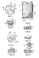
- FIG. 1 is a top plan view of the inside bottom portion of a container or liner for a cylindrical cell of the invention;
- FIG. 2 is a side elevational, partial sectional view of the cell, viewed in the direction of 2-2 of Figure 1;
- FIG. 3 is a partial sectional view along a channel of the container bottom taken along 3-3 of Figure 2;
- FIG. 4 is an underside plan view of the container lid of Figure 2, without the connecting lead posts and plate connecting straps;
- FIG. 5 is a partial sectional view along 5-5 of Figure 4 showing a channel portion of the lid (upside down);
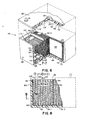
- FIG. 6 depicts in perspective a partial cutaway view of a prismatic battery of the invention;
- FIG. 7 is a partial sectional view of an alternative channel configuration of the container bottom similar to Figure 6 and taken along 7-7;
- FIG. 8 illustrates an elevational, partial sectional view of an alternative embodiment of a battery in accordance with the invention;
- FIG. 9 is an enlarged sectional view along 9-9 of Figure 8 illustrating a further feature;
- FIG. 10 is a view along 10-lG of Figure 8; and
- FIG. 11 is a partial sectional view along 11-11, showing an alternative modification of the channel means.
- Referring first to the embodiment of Figures 1-5, a cylindrical lead-acid cell is shown generally at 10 including a spirally wound (jelly-roll)
cell pack 12 encased more or less snugly within an acid-resistant container comprised ofjar 14, the opening of which is sealed bylid 16. The respective negative and positive terminals protrude through the lid as shown. - The spirally wound cell pack 12 (an example of which is shown in more detail in Figure 8 of Hug et al. U. S. Patent No. 4,112,202) includes
opposite polarity plates 18, 20 formed of an electrochemicallyactive paste material 22 of porous structure adhered to aconductive grid 24. The grid is preferably formed of punched, cast or wrought high hydrogen overvoltage lead or composite grid. Interleaved between the opposite polarity plates iscompressible separator material 26 which extends beyond the edges of the plates both top and bottom to defineedge extension portions 28, 28'. These marginal extensions of the cell pack are in substantial abutting contact with thebottom wall portion 30 of the container jar and/or in substantial abutting contact with thebottom surface 32 ofcontainer lid 16. The cell pack in fact is preferably slightly oversized relative to the container whereby the top and bottomseparator extension portions 28' and 28 and preferably the outer separator wrap (adjacent the container sidewall) exist in a state of compression within the container primarily for optimized vibration resistance. The cell pack is penetrated byaxial void 34. -
Container jar 14 andlid 16 may be encased in an outer, higher modulus container of metal or the like and an outer lid if desired. These and other details such as the plate-to-post connections, Bunsen valve venting means 41 cappingelectrolyte filler hole 42, and the like are shown more particularly in my U. S. Patent No. 4,216,277, hereby incorporated by reference, and in the aforementioned McClelland et al. patent. - In accordance with the invention, at the interface between the bottom-
edge extension 28 of the cell pack'and thebottom surface 30 of the container jar there are provided channel means 36 which generally run transversely to the direction in which the edges of the plates and separators extend. In the case of the cylindrical cell pack, as best seen in Figure 1 a plurality ofchannels 36 extend radially from a centrally located channel ormanifold 40, defining a continuous finger-like passageway 38. This passageway is in communication withcentral void 34 and inturn filler hole 42, providing an unrestricted path for the electrolyte to be delivered to a large portion of the bottom edge of the cell pack. As acid or other electrolyte is introduced intocentral void 34 and it is distributed radially into each ofchannels 36, the electrolyte thereby contacting all layers of thecell pack extension 28 and wicking upwardly more or less uniformly into the interleaved portion of the separator between adjacent plates. Because the separator is preferably compressed against the bottom,portion 35 protrudes into the channel passageways. - In likewise manner, the
top 16 of the container is provided with similar channels 36', defining radial passageways 38' communicating with central vent opening 42, whereby acid or other electrolyte is delivered to the upper extension portion 28' of the cell pack and distributed thereover. Electrolyte is thereby distributed uniformly to the separator extension and thereafter flows downwardly in the interleaved portion between plates where it meets the electrolyte which has -wicked upwardly from the lower portion of the cell. - The
channels 36 not only provide passageways for electrolyte distribution during filling, but also redistribute any electrolyte which is expelled from the cell pack during overcharge or other abusive use. Moreover, the channels provide added mechanical strength to the underside of the container. In this respect, domed or arched channels tapering at 37 on their underside are preferred since they provide added strength to resist bulging of the cell container during use at superatmospheric pressure. - Turning now to the embodiment of Figure 6, there is shown a prismatic battery at 44 comprising a plurality of series connected cells 46-1, 46-2, etc., electrically interconnected and sized to form a battery of desired voltage and capacity. The cells are housed in a
monoblock container 48 and segregated by partitions 50 which may or may not be sealed totop 52. Top 52, however, is liquid and gas-tight sealed along its perimeter to thelower monoblock container 48 at its mouth opening. In the event that partitions 50 do not seal off the cells and a common head space is provided, asingle filling port 54 may be provided, closed during operation of the battery by aresealable Bunsen valve 56. If partitions 50 segregate each cell in liquid tight fashion from one another, separate ports and valves are required for each cell. - Each cell, e.g., 46-1, is comprised of parallel stacked
plates absorbent separator layers 62 are interleaved and compressed between the plates. As in the previous embodiment, the separator layers are permitted to extend at 64, 64' above and below the plate edges, respectively, and are in substantial abutting contact with thetop undersurface 66 oflid 52 andtop surface 68 of the inside bottom of the container. There is also provided anend spacing 70 between the side edges of the cell pack and container wall to allow a path (similar in function tocentral void 34 in Figure 2) for electrolyte to gravitate to the bottom of the individual cells during electrolyte filling. - The bottom of each cell is provided with one or
more channels 72 extending generally transversely to the direction in which the edges of the plates and separators extend. In turn, these transverse channels are fed with electrolyte fromside spaces 70 by interconnectingmanifold channels 74 which run generally longitudinally with respect to the edges of the plates and separators. In this manner, the electrolyte is evenly distributed along the bottom of each cell and hence permitted electrolyte to uniformly wick upwardly into the separator layers and plates. - Similarly,
top 52 may be provided on its undersurface with transversely extendingchannels 721 and longitudinally extending manifolding channels 74'. - As shown in Figure 7,
channels 74, for instance, may be reinforced at their bottom portion at 75 to provide added strength in the area of the channel. - In the embodiment of Figure 8, a battery similar to that of Figure 6 is shown, however the individual cells 76-1, 76-2, etc., are housed in flexible
polymeric bags 78 which are open at their top, and which serve as the intercell partitions of the battery. Each cell, e.g., 76-1, comprises the usualopposite polarity plates flexible polymeric bag 78. The cell packs may have flat parallel plates, flat wound plates or other configuration. - In this embodiment as shown in Figure 10, the
top cover 86 is provided with channels 88 (defining passageways 90) extending generally transversely to the direction in which the edges of the plates and separator extend.Separator portions 89 protrude into the passageways. These transverse channels are in turn intercepted by at least one longitudinally extending, manifolding channel 92 which in turn is in fluid communication with a central electrolyte filler vent hole 94 (which may be capped with a suitable Bunsen valve, not shown). - As shown in the alternative of Figure 9 the
sidewall 85 of the container may be provided with horizontally extendingribs 87 serving to strengthen the case to minimize bulging during internal superatmospheric pressure buildup. - In an alternative embodiment shown in Figure 11, the channel means may be provided by notches or slots 96 provided in the
spearator extension portion 841 rather than in thecontainer wall 86, and defining passageways 97. In this embodiment, as in the previous embodiments, the channel means is still formed at the interface between the extending edge of the cell pack and the abutting wall portion of the container-The previous embodiments of Figures 1-5 and 6 and 7 may also have the channel means provided by slotting of the extended separator material of the cell pack edge rather than the wall portion of the container. - Using this technique in the vacuum filling of 12.5 ampere hour lead-acid spirally wound cylindrical cells, the cells of the invention with channels provided in the top and bottom of the wound element separator extension portions (4
radial segments 1/4 inch wide by 1/8 inch deep in the form of a "plus" inbottom extension - In any of the embodiments the channel means (e.g., channels, notches or slots) may be of any desired cross-sectional configuration, and may be oriented other than perpendicular to the direction in which the plates and separator edges extend. For instance, the crossing
channels - While certain representative embodiments and details have been shown for the purpose of illustrating the invention, it will be apparent to those skilled in this art that various changes and modification may be made therein without departing from the spirit or scope of the invention.
Claims (11)
Applications Claiming Priority (2)
| Application Number | Priority Date | Filing Date | Title |
|---|---|---|---|
| US295479 | 1981-08-24 | ||
| US06/295,479 US4421832A (en) | 1981-08-24 | 1981-08-24 | Electrochemical cell |
Publications (2)
| Publication Number | Publication Date |
|---|---|
| EP0073625A1 true EP0073625A1 (en) | 1983-03-09 |
| EP0073625B1 EP0073625B1 (en) | 1986-05-21 |
Family
ID=23137896
Family Applications (1)
| Application Number | Title | Priority Date | Filing Date |
|---|---|---|---|
| EP82304436A Expired EP0073625B1 (en) | 1981-08-24 | 1982-08-23 | Electrochemical cell |
Country Status (5)
| Country | Link |
|---|---|
| US (1) | US4421832A (en) |
| EP (1) | EP0073625B1 (en) |
| JP (1) | JPH0654679B2 (en) |
| CA (1) | CA1190964A (en) |
| DE (1) | DE3271254D1 (en) |
Cited By (2)
| Publication number | Priority date | Publication date | Assignee | Title |
|---|---|---|---|---|
| GB2177537A (en) * | 1985-06-27 | 1987-01-21 | Chloride Group Plc | Multicell recombination electric storage batteries |
| EP0657952A1 (en) * | 1993-12-07 | 1995-06-14 | Matsushita Electric Industrial Co., Ltd. | Rectangular sealed alkaline storage battery and module battery thereof |
Families Citing this family (19)
| Publication number | Priority date | Publication date | Assignee | Title |
|---|---|---|---|---|
| DE4116253C1 (en) * | 1991-05-17 | 1992-06-04 | Deutsche Automobilgesellschaft Mbh, 3300 Braunschweig, De | |
| US4648177A (en) * | 1983-10-21 | 1987-03-10 | Gates Energy Products, Inc. | Method for producing a sealed lead-acid cell |
| US4637966A (en) * | 1983-10-21 | 1987-01-20 | Gates Energy Products, Inc. | Sealed lead-acid cell |
| US4871428A (en) * | 1988-03-24 | 1989-10-03 | C & D Charter Power Systems, Inc. | Method for in situ forming lead-acid batteries having absorbent separators |
| IT1241289B (en) * | 1990-11-21 | 1993-12-29 | Ginatta Spa | HERMETIC ACID LEAD ACCUMULATOR WITH DIPOLAR ELECTRODES. |
| US5201924A (en) * | 1991-09-03 | 1993-04-13 | General Motors Corporation | Filling mat-immobilized-electrolyte batteries |
| US5851695A (en) | 1992-02-10 | 1998-12-22 | C & D Technologies, Inc. | Recombinant lead-acid cell and long life battery |
| US5409787A (en) * | 1993-02-17 | 1995-04-25 | Electrosource, Inc. | Battery plate compression cage assembly |
| US6004689A (en) * | 1995-09-27 | 1999-12-21 | Bolder Technologies Corporation | Battery case |
| US5895728A (en) * | 1995-09-27 | 1999-04-20 | Bolder Technologies Corp. | Battery case |
| US5871862A (en) * | 1997-05-08 | 1999-02-16 | Optima Batteries, Inc. | Battery paste compositions and electrochemical cells for use therewith |
| US5856037A (en) * | 1997-07-07 | 1999-01-05 | Optima Batteries, Inc. | Battery venting system and method |
| US6065735A (en) * | 1997-09-04 | 2000-05-23 | Clark; Garry E. | Electric valve universal retrofit configuration having misalignment correction |
| US6023146A (en) * | 1998-03-20 | 2000-02-08 | Optima Batteries, Inc. | Battery system electrical connection apparatus and method |
| KR100484115B1 (en) * | 2003-05-21 | 2005-04-19 | 삼성에스디아이 주식회사 | Secondary battery |
| KR100828275B1 (en) | 2003-10-21 | 2008-05-07 | 존슨 컨트롤스 테크놀러지 컴퍼니 | Battery paste materials and methods |
| US7011805B2 (en) | 2004-03-19 | 2006-03-14 | Ges Technologies Ip Gmbh | Production of tetrabasic lead sulfate from solid state reactions for the preparation of active plates to be used in lead-acid batteries |
| US20060039852A1 (en) * | 2004-08-19 | 2006-02-23 | Johnson Controls Technology Company | Method for making lead oxide for lead-acid batteries |
| DE102005017442B4 (en) | 2005-04-15 | 2007-11-29 | Vb Autobatterie Gmbh & Co. Kgaa | Accumulator and lid on this |
Citations (4)
| Publication number | Priority date | Publication date | Assignee | Title |
|---|---|---|---|---|
| US3230112A (en) * | 1961-10-31 | 1966-01-18 | Matsushita Electric Industrial Co Ltd | Sealed alkaline storage battery |
| DE1299057B (en) * | 1967-07-07 | 1969-07-10 | Greutert Werner | Accumulator sealed gas and liquid tight |
| FR2078495A5 (en) * | 1970-02-12 | 1971-11-05 | Tudor Ab | |
| GB1415958A (en) * | 1972-07-12 | 1975-12-03 | Yuasa Battery Co Ltd | Storage batteries |
Family Cites Families (6)
| Publication number | Priority date | Publication date | Assignee | Title |
|---|---|---|---|---|
| US2667527A (en) * | 1949-08-15 | 1954-01-26 | Willard Storage Battery Co | Deferred action battery |
| DE1042681B (en) * | 1953-03-21 | 1958-11-06 | Dr H C Hans Vogt | Permanently sealed, alkaline storage battery |
| DE1071173B (en) * | 1955-12-27 | 1959-12-17 | Yardney International Corporation, New York, N. Y. (V. St. A.) | Device for regulating the electrolyte level in the electrode chambers of accumulators or batteries |
| NL294078A (en) * | 1962-06-15 | |||
| CA1009301A (en) * | 1970-08-03 | 1977-04-26 | John L. Devitt | Maintenance-free lead-acid sealed electrochemical cell with gas recombination |
| US4308322A (en) * | 1980-11-28 | 1981-12-29 | General Motors Corporation | Battery cell and electrolyte circulation pump |
-
1981
- 1981-08-24 US US06/295,479 patent/US4421832A/en not_active Expired - Lifetime
-
1982
- 1982-08-23 EP EP82304436A patent/EP0073625B1/en not_active Expired
- 1982-08-23 DE DE8282304436T patent/DE3271254D1/en not_active Expired
- 1982-08-23 JP JP57146047A patent/JPH0654679B2/en not_active Expired - Lifetime
- 1982-08-24 CA CA000410009A patent/CA1190964A/en not_active Expired
Patent Citations (4)
| Publication number | Priority date | Publication date | Assignee | Title |
|---|---|---|---|---|
| US3230112A (en) * | 1961-10-31 | 1966-01-18 | Matsushita Electric Industrial Co Ltd | Sealed alkaline storage battery |
| DE1299057B (en) * | 1967-07-07 | 1969-07-10 | Greutert Werner | Accumulator sealed gas and liquid tight |
| FR2078495A5 (en) * | 1970-02-12 | 1971-11-05 | Tudor Ab | |
| GB1415958A (en) * | 1972-07-12 | 1975-12-03 | Yuasa Battery Co Ltd | Storage batteries |
Cited By (5)
| Publication number | Priority date | Publication date | Assignee | Title |
|---|---|---|---|---|
| GB2177537A (en) * | 1985-06-27 | 1987-01-21 | Chloride Group Plc | Multicell recombination electric storage batteries |
| EP0207742A3 (en) * | 1985-06-27 | 1987-04-01 | Chloride Group Public Limited Company | Multicell recombination electric storage batteries |
| AU576966B2 (en) * | 1985-06-27 | 1988-09-08 | Chloride Group Public Limited Company | Apertured separator for multicell recombination electric storage batteries |
| EP0657952A1 (en) * | 1993-12-07 | 1995-06-14 | Matsushita Electric Industrial Co., Ltd. | Rectangular sealed alkaline storage battery and module battery thereof |
| US5601946A (en) * | 1993-12-07 | 1997-02-11 | Matsushita Electric Industrial Co., Ltd. | Rectangular sealed alkaline storage battery and module battery thereof |
Also Published As
| Publication number | Publication date |
|---|---|
| EP0073625B1 (en) | 1986-05-21 |
| DE3271254D1 (en) | 1986-06-26 |
| JPH0654679B2 (en) | 1994-07-20 |
| US4421832A (en) | 1983-12-20 |
| CA1190964A (en) | 1985-07-23 |
| JPS5893175A (en) | 1983-06-02 |
Similar Documents
| Publication | Publication Date | Title |
|---|---|---|
| EP0073625B1 (en) | Electrochemical cell | |
| EP0055888B1 (en) | Multicell recombining lead-acid battery | |
| US4780379A (en) | Multicell recombinant lead-acid battery with vibration resistant intercell connector | |
| US4346151A (en) | Multicell sealed rechargeable battery | |
| US4769299A (en) | High rate sealed lead-acid battery with ultrathin plates | |
| CN100431200C (en) | Bipolar battery and method of making bipolar battery | |
| US4447508A (en) | Reduced maintenance explosion damage resistant storage battery | |
| US5626990A (en) | Recombinant lead acid battery and method of making same | |
| CA1181802A (en) | Alkaline electric storage cells | |
| US5227266A (en) | Sealed lead-acid cell having a novel lug, and end cover assembly | |
| US3455739A (en) | Electric storage batteries | |
| CA1179013A (en) | Sealed, maintenance-free, lead-acid batteries for float applications | |
| US4587181A (en) | Lead acid recombination cells | |
| EP0051349B1 (en) | A lead - acid battery construction | |
| EP0024407B1 (en) | Lead acid electric storage batteries | |
| EP0046749A1 (en) | Electric storage batteries | |
| US6235421B1 (en) | Enclosed lead storage battery | |
| EP0143666B1 (en) | Lead acid recombination cells | |
| GB2072929A (en) | Lead acid electric storage batteries | |
| JPH11312506A (en) | Sealed lead-acid battery | |
| JPH04284366A (en) | Enclosed type lead-acid battery | |
| JPS6247972A (en) | Sealed lead-acid battery | |
| GB2071903A (en) | Lead acid electric storage batteries | |
| GB2048556A (en) | Lead acid electric storage batteries | |
| JPS6074360A (en) | Manufacture of lead storage battery |
Legal Events
| Date | Code | Title | Description |
|---|---|---|---|
| PUAI | Public reference made under article 153(3) epc to a published international application that has entered the european phase |
Free format text: ORIGINAL CODE: 0009012 |
|
| AK | Designated contracting states |
Designated state(s): DE FR GB IT |
|
| 17P | Request for examination filed |
Effective date: 19830812 |
|
| ITF | It: translation for a ep patent filed | ||
| GRAA | (expected) grant |
Free format text: ORIGINAL CODE: 0009210 |
|
| AK | Designated contracting states |
Kind code of ref document: B1 Designated state(s): DE FR GB IT |
|
| REF | Corresponds to: |
Ref document number: 3271254 Country of ref document: DE Date of ref document: 19860626 |
|
| ET | Fr: translation filed | ||
| PLBE | No opposition filed within time limit |
Free format text: ORIGINAL CODE: 0009261 |
|
| STAA | Information on the status of an ep patent application or granted ep patent |
Free format text: STATUS: NO OPPOSITION FILED WITHIN TIME LIMIT |
|
| 26N | No opposition filed | ||
| REG | Reference to a national code |
Ref country code: GB Ref legal event code: 732 |
|
| ITTA | It: last paid annual fee | ||
| PGFP | Annual fee paid to national office [announced via postgrant information from national office to epo] |
Ref country code: FR Payment date: 19950717 Year of fee payment: 14 |
|
| PGFP | Annual fee paid to national office [announced via postgrant information from national office to epo] |
Ref country code: DE Payment date: 19950725 Year of fee payment: 14 |
|
| PGFP | Annual fee paid to national office [announced via postgrant information from national office to epo] |
Ref country code: GB Payment date: 19950727 Year of fee payment: 14 |
|
| REG | Reference to a national code |
Ref country code: FR Ref legal event code: TP |
|
| REG | Reference to a national code |
Ref country code: GB Ref legal event code: 732E |
|
| PG25 | Lapsed in a contracting state [announced via postgrant information from national office to epo] |
Ref country code: GB Effective date: 19960823 |
|
| GBPC | Gb: european patent ceased through non-payment of renewal fee |
Effective date: 19960823 |
|
| PG25 | Lapsed in a contracting state [announced via postgrant information from national office to epo] |
Ref country code: FR Effective date: 19970430 |
|
| PG25 | Lapsed in a contracting state [announced via postgrant information from national office to epo] |
Ref country code: DE Effective date: 19970501 |
|
| REG | Reference to a national code |
Ref country code: FR Ref legal event code: ST |