EP0072803B1 - Cylinder-lock attachment means - Google Patents
Cylinder-lock attachment means Download PDFInfo
- Publication number
- EP0072803B1 EP0072803B1 EP81903055A EP81903055A EP0072803B1 EP 0072803 B1 EP0072803 B1 EP 0072803B1 EP 81903055 A EP81903055 A EP 81903055A EP 81903055 A EP81903055 A EP 81903055A EP 0072803 B1 EP0072803 B1 EP 0072803B1
- Authority
- EP
- European Patent Office
- Prior art keywords
- cylinder
- plug element
- lock
- hole
- core
- Prior art date
- Legal status (The legal status is an assumption and is not a legal conclusion. Google has not performed a legal analysis and makes no representation as to the accuracy of the status listed.)
- Expired
Links
- 230000002093 peripheral effect Effects 0.000 claims abstract description 11
- 230000000717 retained effect Effects 0.000 claims description 2
- 238000007789 sealing Methods 0.000 abstract 2
- 238000004873 anchoring Methods 0.000 description 6
- 238000010276 construction Methods 0.000 description 1
- 230000002452 interceptive effect Effects 0.000 description 1
- 238000000034 method Methods 0.000 description 1
- 230000002787 reinforcement Effects 0.000 description 1
- 125000006850 spacer group Chemical group 0.000 description 1
Images


Classifications
-
- E—FIXED CONSTRUCTIONS
- E05—LOCKS; KEYS; WINDOW OR DOOR FITTINGS; SAFES
- E05B—LOCKS; ACCESSORIES THEREFOR; HANDCUFFS
- E05B9/00—Lock casings or latch-mechanism casings ; Fastening locks or fasteners or parts thereof to the wing
- E05B9/08—Fastening locks or fasteners or parts thereof, e.g. the casings of latch-bolt locks or cylinder locks to the wing
- E05B9/082—Fastening locks or fasteners or parts thereof, e.g. the casings of latch-bolt locks or cylinder locks to the wing with concealed screws
-
- Y—GENERAL TAGGING OF NEW TECHNOLOGICAL DEVELOPMENTS; GENERAL TAGGING OF CROSS-SECTIONAL TECHNOLOGIES SPANNING OVER SEVERAL SECTIONS OF THE IPC; TECHNICAL SUBJECTS COVERED BY FORMER USPC CROSS-REFERENCE ART COLLECTIONS [XRACs] AND DIGESTS
- Y10—TECHNICAL SUBJECTS COVERED BY FORMER USPC
- Y10S—TECHNICAL SUBJECTS COVERED BY FORMER USPC CROSS-REFERENCE ART COLLECTIONS [XRACs] AND DIGESTS
- Y10S70/00—Locks
- Y10S70/57—Screw guard
-
- Y—GENERAL TAGGING OF NEW TECHNOLOGICAL DEVELOPMENTS; GENERAL TAGGING OF CROSS-SECTIONAL TECHNOLOGIES SPANNING OVER SEVERAL SECTIONS OF THE IPC; TECHNICAL SUBJECTS COVERED BY FORMER USPC CROSS-REFERENCE ART COLLECTIONS [XRACs] AND DIGESTS
- Y10—TECHNICAL SUBJECTS COVERED BY FORMER USPC
- Y10T—TECHNICAL SUBJECTS COVERED BY FORMER US CLASSIFICATION
- Y10T70/00—Locks
- Y10T70/50—Special application
- Y10T70/5611—For control and machine elements
- Y10T70/5854—Bolt, nut, stud, stud-cap
- Y10T70/5867—Encased
-
- Y—GENERAL TAGGING OF NEW TECHNOLOGICAL DEVELOPMENTS; GENERAL TAGGING OF CROSS-SECTIONAL TECHNOLOGIES SPANNING OVER SEVERAL SECTIONS OF THE IPC; TECHNICAL SUBJECTS COVERED BY FORMER USPC CROSS-REFERENCE ART COLLECTIONS [XRACs] AND DIGESTS
- Y10—TECHNICAL SUBJECTS COVERED BY FORMER USPC
- Y10T—TECHNICAL SUBJECTS COVERED BY FORMER US CLASSIFICATION
- Y10T70/00—Locks
- Y10T70/70—Operating mechanism
- Y10T70/7441—Key
- Y10T70/7486—Single key
- Y10T70/7508—Tumbler type
- Y10T70/7559—Cylinder type
- Y10T70/7655—Cylinder attaching or mounting means
-
- Y—GENERAL TAGGING OF NEW TECHNOLOGICAL DEVELOPMENTS; GENERAL TAGGING OF CROSS-SECTIONAL TECHNOLOGIES SPANNING OVER SEVERAL SECTIONS OF THE IPC; TECHNICAL SUBJECTS COVERED BY FORMER USPC CROSS-REFERENCE ART COLLECTIONS [XRACs] AND DIGESTS
- Y10—TECHNICAL SUBJECTS COVERED BY FORMER USPC
- Y10T—TECHNICAL SUBJECTS COVERED BY FORMER US CLASSIFICATION
- Y10T70/00—Locks
- Y10T70/70—Operating mechanism
- Y10T70/7441—Key
- Y10T70/7486—Single key
- Y10T70/7508—Tumbler type
- Y10T70/7559—Cylinder type
- Y10T70/7661—Detachable or removable cylinder
-
- Y—GENERAL TAGGING OF NEW TECHNOLOGICAL DEVELOPMENTS; GENERAL TAGGING OF CROSS-SECTIONAL TECHNOLOGIES SPANNING OVER SEVERAL SECTIONS OF THE IPC; TECHNICAL SUBJECTS COVERED BY FORMER USPC CROSS-REFERENCE ART COLLECTIONS [XRACs] AND DIGESTS
- Y10—TECHNICAL SUBJECTS COVERED BY FORMER USPC
- Y10T—TECHNICAL SUBJECTS COVERED BY FORMER US CLASSIFICATION
- Y10T70/00—Locks
- Y10T70/70—Operating mechanism
- Y10T70/7441—Key
- Y10T70/7486—Single key
- Y10T70/7508—Tumbler type
- Y10T70/7559—Cylinder type
- Y10T70/7667—Operating elements, parts and adjuncts
-
- Y—GENERAL TAGGING OF NEW TECHNOLOGICAL DEVELOPMENTS; GENERAL TAGGING OF CROSS-SECTIONAL TECHNOLOGIES SPANNING OVER SEVERAL SECTIONS OF THE IPC; TECHNICAL SUBJECTS COVERED BY FORMER USPC CROSS-REFERENCE ART COLLECTIONS [XRACs] AND DIGESTS
- Y10—TECHNICAL SUBJECTS COVERED BY FORMER USPC
- Y10T—TECHNICAL SUBJECTS COVERED BY FORMER US CLASSIFICATION
- Y10T70/00—Locks
- Y10T70/70—Operating mechanism
- Y10T70/7441—Key
- Y10T70/7486—Single key
- Y10T70/7508—Tumbler type
- Y10T70/7559—Cylinder type
- Y10T70/7667—Operating elements, parts and adjuncts
- Y10T70/7684—Plug
-
- Y—GENERAL TAGGING OF NEW TECHNOLOGICAL DEVELOPMENTS; GENERAL TAGGING OF CROSS-SECTIONAL TECHNOLOGIES SPANNING OVER SEVERAL SECTIONS OF THE IPC; TECHNICAL SUBJECTS COVERED BY FORMER USPC CROSS-REFERENCE ART COLLECTIONS [XRACs] AND DIGESTS
- Y10—TECHNICAL SUBJECTS COVERED BY FORMER USPC
- Y10T—TECHNICAL SUBJECTS COVERED BY FORMER US CLASSIFICATION
- Y10T70/00—Locks
- Y10T70/70—Operating mechanism
- Y10T70/7441—Key
- Y10T70/7915—Tampering prevention or attack defeating
- Y10T70/7949—Yielding or frangible connections
-
- Y—GENERAL TAGGING OF NEW TECHNOLOGICAL DEVELOPMENTS; GENERAL TAGGING OF CROSS-SECTIONAL TECHNOLOGIES SPANNING OVER SEVERAL SECTIONS OF THE IPC; TECHNICAL SUBJECTS COVERED BY FORMER USPC CROSS-REFERENCE ART COLLECTIONS [XRACs] AND DIGESTS
- Y10—TECHNICAL SUBJECTS COVERED BY FORMER USPC
- Y10T—TECHNICAL SUBJECTS COVERED BY FORMER US CLASSIFICATION
- Y10T70/00—Locks
- Y10T70/80—Parts, attachments, accessories and adjuncts
- Y10T70/8432—For key-operated mechanism
- Y10T70/8459—Housings
- Y10T70/8541—Mounting arrangements
-
- Y—GENERAL TAGGING OF NEW TECHNOLOGICAL DEVELOPMENTS; GENERAL TAGGING OF CROSS-SECTIONAL TECHNOLOGIES SPANNING OVER SEVERAL SECTIONS OF THE IPC; TECHNICAL SUBJECTS COVERED BY FORMER USPC CROSS-REFERENCE ART COLLECTIONS [XRACs] AND DIGESTS
- Y10—TECHNICAL SUBJECTS COVERED BY FORMER USPC
- Y10T—TECHNICAL SUBJECTS COVERED BY FORMER US CLASSIFICATION
- Y10T70/00—Locks
- Y10T70/80—Parts, attachments, accessories and adjuncts
- Y10T70/8432—For key-operated mechanism
- Y10T70/8568—Escutcheons
Definitions
- the present invention relates to a cylinder-lock attachment means, sometimes referred to as a cylinder-lock fitting, of the kind comprising an escutcheon or the like; a cylinder lock; one or more headed screws for securing the cylinder lock; and a hole for respective screws, said hole having a widened portion in which the screw head of respective screws is seated, a screw head plug element anchored in the cylinder lock.
- Previously known cylinder-lock attachment means of this kind are normally designed to be mounted on the inside of a door, and to this end are designed to fit into a standard-size hole made in the door for this purpose, the diameter of the hole in the case of Swedish standards being 40 mm.
- the headed screws are passed through the cylinder lock and are normally screwed into a corresponding cylinder lock on the outside of the door, in which case the screws are passed through a lock housing arranged in a recess in the door and accommodating a lock mechanism - normally a latch plunger mechanism - which can be activated by the cylinder locks.
- the escutcheons or cylinder fittings may also be mutually connected together by means of one or more screws, which then also pass through the lock housing.
- the cylinder lock located on the outside of the door is joined to the cylinder lock on the inside of the door by means of screws whose heads are located in the "inner" lock and which cannot therefore be reached from the outside of the door.
- the screw-heads can be reached from the inside of the door, and tightening of the screws with a screw driver causes the two cylinder locks to be urged towards each other while being accurately fixed and aligned relative to each other and to the door.
- a cylinder-lock attachment fitting comprising an escutcheon or the like, a cylinder lock, one or more headed screws for securing the cylinder lock, a hole for respective screws, said holes having a widened portion in which the head of respective screw seats, a screw-head plug element anchored in the cylinder lock, a securing means for securing the anchorage of the plug element, said securing means upon rotation of said cylinder core to a given position by means of a key being movable to a release position in which the plug element can be withdrawn from said widened hole portion, characterized in that said securing means permits removal of said plug element while the cylinder core is retained within its housing, and in that said securing means comprises a peripheral hole which is located in the cylinder core and which extends radially to the axis of the core, a pin engaging said plug element and movable in a bore extending between a hole accommodating the plug element and the cylinder core and extending at right angles to
- the pin constitutes a reliable member for anchoring the plug element, said anchorage being effected by passing the pin into a recess, for example into a waisted portion of the plug element.
- the securing pin will be urged inwardly against the bias of said spring, towards the centre of the cylinder core.
- the pin suitably has a rounded end, while the recess, for example the waisted portion of the plug element, has a concave shape.
- the plug element suitably has at its outer end a weakened grip portion, e.g. of frusto-conical configuration, arranged to fracture if force is used there against when attempting to withdraw the plug element.
- a weakened grip portion e.g. of frusto-conical configuration
- an attachment-fitting arrangement is of this kind and is characterized by one or more holes arranged in the end plate in register with the widened hole portions in the cylinder lock accommodating the plug element or elements, said plug element or elements being passed through said holes in the end plate so as to lock said end plate against rotation.
- the relatively simple plug element which renders the anchoring screws of the cylinder lock inaccessible obtains the further function of preventing rotation of the end plate or catch plate, which in turn also renders inaccessible the screw heads located behind the said end plate of the screws which connect the escutcheon of the attachment-fitting arrangement to a corresponding escutcheon on the other side of the door, since the catch plate or end plate cannot be removed.
- the plug element is accommodated in a special hole in the cylinder lock and is provided with a head member which engages directly, or indirectly via a cover plate, two mutually adjacent screw heads, so as to prevent the screws being loosened.
- the actual cylinder lock is preferably of circular-cylindrical shape.
- the cylinder lock may be enclosed in a cover member which covers the screw heads and the plug element, and which has a hole for permitting access to the cylinder core.
- the hole may be surrounded by a fitting or a plate having a more decorative purpose, i.e. not needing to be permanently anchored.
- an attachment fitting for a cylinder lock comprising a so-called cylinder lock fitting 1 with an escutcheon 2 having a male part 2d arranged to be housed in a 40 mm hole, and an end plate or catch plate 17 having a peripheral screw thread which co-acts with corresponding screw threads on the escutcheon 2, enabling said plate to be screwed thereinto.
- the end plate or catch plate 17 is provided with a circular hole 17a, which provides access to the key slot of a cylinder core (not shown in Figs. 1 and 2) arranged in the lock fitting.
- the catch plate also has two holes 17b, which are excentrically located relative to the axis of said catch plate and the purpose and function of which will be described in more detail hereinafter.
- the escutcheon 2 and the male part 2d are also provided with a recess 2a for accommodating a cylinder lock.
- the lock fitting 1 is connected by means of four robust screws 16 to an oppositely located lock fitting 1', which is of similar design to the lock fitting 1.
- the lock fitting 1' comprises an escutcheon 2' having a male part 2'd, a recess 2'a for a cylinder lock, and a catch plate or end plate 17' having a round hole 17'a corresponding to the position of the key slot for the plug of a cylinder lock.
- the end plate 17' of the lock fitting 1' lacks excentrically located holes corresponding to the hole 17b of the end plate or catch plate 17 of the lock fitting 1.
- Figures 3 and 4 illustrate a cylindrical lock 3 intended to be accommodated in the escutcheon 2 of the lock fitting 1 shown to the left of Figure 1.
- the cylinder lock 3 is partially of conventional design and is provided with a rotatable core 3a having a key slot 3b. Above the core 3a are two holes 5 for anchoring screws 4 provided with heads 4a, said heads being accommodated in a widened forward hole part 5a of the holes 5, so that said heads 4a seat in the widened hole parts.
- the anchoring screws 4 are screwed, in a normal way, into screw-threaded holes of an oppositely situated cylinder lock 3' accommodated in the escutcheon 2' (not shown in Figures 1-4) of the other cylinder fitting 1'.
- a plug element 6 in the form of a cylindrical body having a centrally located recess in the form of a waisted portion 6a.
- the plug element 6 is arranged for rotation in the hole part 5a and is adapted to co-act with a securing means in the form of a pin or peg 7 movably arranged in a bore 8 and extending at right angles to the axis of the hole part 5a.
- a further plug element 6 and associated securing pin 7 are provided at the other side of the cylinder lock, and hence the core must be rotated further in the other direction before this additional plug element can be removed.
- end 7a of the securing pin 7 co-acting with the waisted portion 6a is curved or bent, and consequently, when the core is located in its correct position, the securing pin will automatically be pressed in when the plug element 6 is withdrawn.
- the plug element 6 is withdrawn by grasping the frusto-conical peg 6b located on the outer end of the plug element, with a pair of pliers or the like.
- the conical peg 6b is arranged to fracture if excessive force is exerted thereonto.
- Figure 5 illustrates the two frusto-conical ends 6b of plug element 6, subsequent to mounting said elements 6 in position in the left-hand cylinder fitting 1' and securing or fixing the position of said elements by means of said securing elements, the core 3a being subsequently rotated to the position in which the key can be removed.
- the two cylinder locks 3 and 3' are then anchored together by means of screws 4, the heads of which (not shown in Figures 5 and 6) are inaccessible as a result of the secured plug elements, the ends 6b of which are shown in the two figures.
- the escutcheons 2, 2' of the cylinder fittings 1, 1' are shown joined together by means of four screws 16, the heads 16a of which are accommodated in the space 2b in the left-hand escutcheon 2, inwardly of the catch plate or end plate 17.
- one screw head 16a of two mutually adjacent screws 16 passes through a spacer plate 19, preventing the screw heads from interfering with one another.
- a perforated support plate 20 for receiving the plug element 6 and the core 3a of the cylinder lock 3.
- Support plate 20 of varying thicknesses can be arranged in position independence on the type of cylinder lock used.
- the right-hand escutcheon 2' is also provided with a screw-in end plate 17', which lacks recesses for plug elements, however, (cf. Fig. 2).
- the correct key is then inserted into the cylinder lock, and the core 3a of the lock rotated until the bore 8 ( Figure 3) and the peripheral hole 10 are in register with one another.
- the plug element 6 is then pressed in, which is made possible by inward movement of the securing pin 7 in the hole 9, against the bias of the spring 10.
- the cylinder core is then rotated in the other direction, whereafter the operation is repeated with the other plug element 6.
- the core of the cylinder lock is then rotated, so that the key recess takes a vertical position and the key is removed, the screw heads of the cylinder lock are plugged and secured so as to be inaccessible.
- the outwardly projecting ends 5b of the securing pins 6 prevent rotation of the catch plate or end plate, which prevents said plate from being removed from the escutcheon 2. Consequently, the heads 16a of the four screws 16 joining the escutcheons 2 and 2' are also inaccessible.
- Figures 7-9 illustrate a modified embodiment in which two circular-cylindrical cylinder locks 3, 3' arranged on both sides of a door (not shown) are joined together by means of four screws 4.
- the plug element 6 is not accommodated in the same widened hole part 5a as the screw heads 4a. Instead, there is provided between two such widened hole parts 5a a separate hole 12 for receiving the plug element 6, which, in the illustrated embodiment, in addition to having a waisted portion 6a for co-action with a securing pin 7, also has a forward head 6c which carries a frusto-conical peg 6b.
- the element 6 can suitably be called a catch, since the head 6c is intended to engage two mutually adjacent screw heads 4a in a manner to prevent the screws 4 from being removed even though the heads can be reached with a spanner or some other tool, provided that that element 6 is in position.
- the head 6c of the plug element 6 engages the heads 4a of two mutually adjacent screws via a separate plate 13, which prevents the heads being reached with a screwdriver or like tool.
- the cylinder lock when mounted onto a door, is embraced by a cover 20 having a mainly decorative purpose, i.e. is not intended to increase the reliability of the arrangement against forced entry.
- the cover covers the screw heads 4a and the plug elements 6, and is provided with a hole for permitting access to the cylinder core 3a.
- the cylinder lock and cover may also be surrounded by an escutcheon 2, which is mounted on the door and, unlike the escutcheons 2 referred to in connection with the embodiment first-described, need not necessarily be connected to a corresponding escutcheon, but may be fastened to the door in a conventional manner.
- the screws 4 connecting the two cylinder locks located on respective sides of the door, together with the plug element which hides the screw heads and prevents them from being turned to unscrew the screws, are sufficient to render the entire lock arrangement safe against forced entry.
- the basic concept of the invention of anchoring a plug element by means of a securing pin radially movable relative to the plug of the cylinder lock, so that the plug element can only be removed by persons possessing a key which fits the cylinder lock, can also be used in other connections, where it is desired to strengthen the attachment of a cylinder lock in a manner which makes forced entry more difficult.
- the actual cylinder lock may have different forms and designs, and that the form of the escutcheon or lock fitting can also vary.
- the robust fitting 1 with integrated escutcheon 2 of the embodiment first-described has been replaced in the embodiment according to Figures 7-11 with a thin cover 20 and separate escutcheon 2.
- cylinder lock it is also possible instead to form part of the actual cylinder lock as a lock fitting or escutcheon. Further, it is not necessary to connect together two cylinder locks located on a respective side of a door. When only one cylinder lock is used, the cylinder lock can be made inaccessible by fitting and anchoring the same while applying the basic idea of the invention.
Landscapes
- Engineering & Computer Science (AREA)
- Mechanical Engineering (AREA)
- Lock And Its Accessories (AREA)
- Underground Structures, Protecting, Testing And Restoring Foundations (AREA)
Abstract
Description
- The present invention relates to a cylinder-lock attachment means, sometimes referred to as a cylinder-lock fitting, of the kind comprising an escutcheon or the like; a cylinder lock; one or more headed screws for securing the cylinder lock; and a hole for respective screws, said hole having a widened portion in which the screw head of respective screws is seated, a screw head plug element anchored in the cylinder lock.
- Previously known cylinder-lock attachment means of this kind are normally designed to be mounted on the inside of a door, and to this end are designed to fit into a standard-size hole made in the door for this purpose, the diameter of the hole in the case of Swedish standards being 40 mm.
- The headed screws are passed through the cylinder lock and are normally screwed into a corresponding cylinder lock on the outside of the door, in which case the screws are passed through a lock housing arranged in a recess in the door and accommodating a lock mechanism - normally a latch plunger mechanism - which can be activated by the cylinder locks.
- The escutcheons or cylinder fittings may also be mutually connected together by means of one or more screws, which then also pass through the lock housing.
- Thus, the cylinder lock located on the outside of the door is joined to the cylinder lock on the inside of the door by means of screws whose heads are located in the "inner" lock and which cannot therefore be reached from the outside of the door. The screw-heads, however, can be reached from the inside of the door, and tightening of the screws with a screw driver causes the two cylinder locks to be urged towards each other while being accurately fixed and aligned relative to each other and to the door.
- An arrangement of this kind creates problems when the door in question cannot be considered to have an inside and an outside, i.e. both sides of the door can be considered as the "outside". This is primarily the case with locales and rooms which have additional entrance possibilities. In this case it is relatively simple for a person to unlawfully activate the "inner" cylinder lock, by simply unscrewing the readily accessible screws, removing the cylinder lock and then releasing the latch plunger mechanism in the lock housing, in a suitable manner.
- Normal houses and flats present a similar problem, particularly if an intruder is able to gain entrance through a readily forced balcony door, a lower floor window or the like, whereafter the cylinder lock on the "inside" of a door can readily be opened in the aforesaid manner, enabling the intruder to leave through a conventional exit, normally the main front door, together with any goods stolen. It will readily be understood that much less attention will be paid to an intruder who uses a normal exit as his retreat path, and that he or she will be more difficult to discover than if leaving the building, together with any goods stolen, via a lower floor window, balcony door or the like.
- It will be obvious from the aforegoing that there is a need
- firstly to render all screws in an "inner" cylinder lock inaccessible, and
- secondly to reinforce the attachment-fitting arrangement, including both the inner and outer escutcheons as a whole, so as to increase the resistance against the use of force.
- Those methods previously proposed for hiding or covering both the inside and outside of the screws joining the locking cylinders and escutcheons respectively in a cylinder-lock fitting arrangement of the kind meant here have not been satisfactory. Thus, only a small amount of force has been needed to render the heads of the screws accessible. Furthermore, it has been relatively simple to remove the attachment fittings with the aid of a crowbar or like forcing implement, and then to activate the locking mechanism in the lock housing in a manner to enable the door to be opened.
- In other prior arrangements the screws are accessible upon removing the cylinder core from its housing.
- US-A-3 715 899 (McCullum) describes such an arrangement in which the cylinder lock itself forms the plug element denying access to the screw heads. This lock necessitates a special 8- shaped opening in each cylinder for the reception of a correspondingly shaped core which, however, is no generally desirable shape of a cylinder- core.
- According to the present invention there is accomplished a cylinder-lock attachment fitting comprising an escutcheon or the like, a cylinder lock, one or more headed screws for securing the cylinder lock, a hole for respective screws, said holes having a widened portion in which the head of respective screw seats, a screw-head plug element anchored in the cylinder lock, a securing means for securing the anchorage of the plug element, said securing means upon rotation of said cylinder core to a given position by means of a key being movable to a release position in which the plug element can be withdrawn from said widened hole portion, characterized in that said securing means permits removal of said plug element while the cylinder core is retained within its housing, and in that said securing means comprises a peripheral hole which is located in the cylinder core and which extends radially to the axis of the core, a pin engaging said plug element and movable in a bore extending between a hole accommodating the plug element and the cylinder core and extending at right angles to the axis of said hole, the axis of said bore in said given position of said cylinder core coinciding with the axis of the peripheral hole in said cylinder core, and a spring located in the peripheral hole, whereat in said given angular position of the cylinder core said pin is movable inwardly to its release position, against the bias of said spring, in which position the plug element can be withdrawn.
- Despite its simplicity the pin constitutes a reliable member for anchoring the plug element, said anchorage being effected by passing the pin into a recess, for example into a waisted portion of the plug element. When the plus element is withdrawn, the securing pin will be urged inwardly against the bias of said spring, towards the centre of the cylinder core.
- To facilitate co-action between the pin and the plug element, the pin suitably has a rounded end, while the recess, for example the waisted portion of the plug element, has a concave shape.
- Further, the plug element suitably has at its outer end a weakened grip portion, e.g. of frusto-conical configuration, arranged to fracture if force is used there against when attempting to withdraw the plug element.
- In a previously known attachment-fitting arrangement of the kind mentioned in the introduction, although lacking both the plug element and the securing means therefor, there is provided in the cylinder fitting outside the cylinder lock one or more holes and a corresponding number of headed screws which are inserted through said holes and by means of which the cylinder fitting can be connected to a further cylinder fitting on the other side of a door or the like on which the cylinder fitting is mounted. In the end of the cylinder fitting there is an internal screw thread arranged to cooperate with a corresponding screw thread on the periphery of an end plate arranged to cover said screw heads when said plate is screwed into the cylinder fitting, and with a hole which registered with the core of the cylinder lock, so as to leave the key slot of the core accessible.
- One embodiment of an attachment-fitting arrangement according to the invention is of this kind and is characterized by one or more holes arranged in the end plate in register with the widened hole portions in the cylinder lock accommodating the plug element or elements, said plug element or elements being passed through said holes in the end plate so as to lock said end plate against rotation.
- Thus, the relatively simple plug element which renders the anchoring screws of the cylinder lock inaccessible obtains the further function of preventing rotation of the end plate or catch plate, which in turn also renders inaccessible the screw heads located behind the said end plate of the screws which connect the escutcheon of the attachment-fitting arrangement to a corresponding escutcheon on the other side of the door, since the catch plate or end plate cannot be removed.
- According to a modified embodiment, the plug element is accommodated in a special hole in the cylinder lock and is provided with a head member which engages directly, or indirectly via a cover plate, two mutually adjacent screw heads, so as to prevent the screws being loosened. In this instance, the actual cylinder lock is preferably of circular-cylindrical shape. For aesthetic reasons the cylinder lock may be enclosed in a cover member which covers the screw heads and the plug element, and which has a hole for permitting access to the cylinder core. The hole may be surrounded by a fitting or a plate having a more decorative purpose, i.e. not needing to be permanently anchored.
- Exemplary embodiments of the invention will now be described in more detail with reference to the accompanying drawings.
- Figure 1 is a perspective view of a first embodiment of a cylinder lock fitting connected to a similar cylinder lock fitting by means of four screws.
- Figure 2 is a similar perspective view showing the two lock fittings illustrated in Figure 1 as seen from the other side.
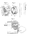
- Figure 3 is a partially cut-away end view of a cylinder lock arranged to be accommodated in a cylinder lock fitting according to Figure 1 and provided with a plug and securing arrangement according to the invention.
- Figure 4 is a partially cut-away side view of the cylinder lock shown in Figure 3, together with associated plug element and securing pin.
- Figure 5 is a perspective view of two mutually connected cylinder lock fittings according to Figure 1, subsequently to mounting the associated cylinder lock and plug element.
- Figure 6 is a sectional view of the cylinder lock fitting arrangement shown in Figure 5, taken on the line VI-VI.
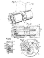
- Figure 7 is a perspective view of a modified attachment-fitting arrangement, in which the two cylinder locks are of circular-cylindrical configuration, and the plug element is arranged in a separate hole between two screw holes.
- Figure 8 is a sectional view taken on the line VIII-VIII in Figure 7.
- Figure 9 is a partially cut-away front view of the cylinder lock arrangement illustrated in Figure 7.
- Figure 10 is a sectional view corresponding to part of Figure 8, of a further embodiment in which a plug element engages two mutually adjacent screw heads via a separate cover plate.
- Figure 11 is a perspective view of a cylinder-lock arrangement shown in Figure 7 or Figure 10 mounted onto a door, in which the cylinder lock is surrounded by a cover and an external plate attached to the door.
- With reference to Figures 1 and 2 there is shown an attachment fitting for a cylinder lock, said attachment fitting comprising a so-called cylinder lock fitting 1 with an
escutcheon 2 having amale part 2d arranged to be housed in a 40 mm hole, and an end plate orcatch plate 17 having a peripheral screw thread which co-acts with corresponding screw threads on theescutcheon 2, enabling said plate to be screwed thereinto. The end plate orcatch plate 17 is provided with acircular hole 17a, which provides access to the key slot of a cylinder core (not shown in Figs. 1 and 2) arranged in the lock fitting. The catch plate also has twoholes 17b, which are excentrically located relative to the axis of said catch plate and the purpose and function of which will be described in more detail hereinafter. - As will be seen from Figure 2, the
escutcheon 2 and themale part 2d are also provided with a recess 2a for accommodating a cylinder lock. - The
lock fitting 1 is connected by means of fourrobust screws 16 to an oppositely located lock fitting 1', which is of similar design to the lock fitting 1. Thus, the lock fitting 1' comprises an escutcheon 2' having amale part 2'd, a recess 2'a for a cylinder lock, and a catch plate or end plate 17' having a round hole 17'a corresponding to the position of the key slot for the plug of a cylinder lock. - The end plate 17' of the lock fitting 1', however, lacks excentrically located holes corresponding to the
hole 17b of the end plate orcatch plate 17 of the lock fitting 1. - The four
screws 16 connecting theescutcheons 2 and 2' of the two lock fittings together provide a considerable reinforcement in relation to conventional arrangements. - Figures 3 and 4 illustrate a
cylindrical lock 3 intended to be accommodated in theescutcheon 2 of thelock fitting 1 shown to the left of Figure 1. - The
cylinder lock 3 is partially of conventional design and is provided with arotatable core 3a having akey slot 3b. Above thecore 3a are twoholes 5 for anchoringscrews 4 provided withheads 4a, said heads being accommodated in a widenedforward hole part 5a of theholes 5, so that saidheads 4a seat in the widened hole parts. - The anchoring
screws 4 are screwed, in a normal way, into screw-threaded holes of an oppositely situated cylinder lock 3' accommodated in the escutcheon 2' (not shown in Figures 1-4) of the other cylinder fitting 1'. - In order to make the
screw heads 4a inaccessible, there is arranged in the widenedhole part 5a, in front of the screw heads, aplug element 6 in the form of a cylindrical body having a centrally located recess in the form of a waistedportion 6a. Theplug element 6 is arranged for rotation in thehole part 5a and is adapted to co-act with a securing means in the form of a pin or peg 7 movably arranged in abore 8 and extending at right angles to the axis of thehole part 5a. - In the position occupied by the
core 3a in Figure 3 - which position can only be reached by inserting the correct key into thekey recess 3b and turning the core to said position - thebore 8 is in register with ahole 9 arranged peripherally of the core, in which hole there is provided aspring 10 and a surroundingsleeve 11. Thus, thesecuring pin 7 can be urged in this position inwardly towards the axis of the core, against the bias of thespring 10, permitting theplug element 6 to be withdrawn from thehole part 5a. Consequently, theplug element 6 can only be removed by using the correct key and rotating the core to the position shown in Figure 3. - As will be seen from Figure 3, a
further plug element 6 and associated securingpin 7 are provided at the other side of the cylinder lock, and hence the core must be rotated further in the other direction before this additional plug element can be removed. - In the embodiment illustrated in Figures 3 and 4, and
end 7a of the securingpin 7 co-acting with the waistedportion 6a is curved or bent, and consequently, when the core is located in its correct position, the securing pin will automatically be pressed in when theplug element 6 is withdrawn. In practice, theplug element 6 is withdrawn by grasping the frusto-conical peg 6b located on the outer end of the plug element, with a pair of pliers or the like. Theconical peg 6b is arranged to fracture if excessive force is exerted thereonto. Thus, if an attempt is made to withdraw the plug element by grasping thepeg 6b with a pair of pliers, without moving the core to the position shown in Figures 3 and 4, thepeg 6b will fracture, causing even greater difficulty in removing the plug element by force. - The construction of the two
cylinder fittings 1 and 1' in connection with alock housing 22 mounted in position on a door (not shown) is illustrated in Figures 5 and 6. Figure 5 illustrates the two frusto-conical ends 6b ofplug element 6, subsequent to mounting saidelements 6 in position in the left-hand cylinder fitting 1' and securing or fixing the position of said elements by means of said securing elements, thecore 3a being subsequently rotated to the position in which the key can be removed. The twocylinder locks 3 and 3' are then anchored together by means ofscrews 4, the heads of which (not shown in Figures 5 and 6) are inaccessible as a result of the secured plug elements, theends 6b of which are shown in the two figures. - The
escutcheons 2, 2' of thecylinder fittings 1, 1' are shown joined together by means of fourscrews 16, theheads 16a of which are accommodated in the space 2b in the left-hand escutcheon 2, inwardly of the catch plate orend plate 17. In the Figure 6 embodiment, onescrew head 16a of two mutuallyadjacent screws 16 passes through aspacer plate 19, preventing the screw heads from interfering with one another. - Inwardly of the
catch plate 17, which has peripheral screw threads 17c and is screwed into aninternal screw thread 2c in theescutcheon 2, there is arranged a perforatedsupport plate 20 for receiving theplug element 6 and the core 3a of thecylinder lock 3.Support plate 20 of varying thicknesses can be arranged in position independence on the type of cylinder lock used. The right-hand escutcheon 2' is also provided with a screw-in end plate 17', which lacks recesses for plug elements, however, (cf. Fig. 2). - Subsequent to placing the cylinder fittings in position, the
screws support plate 20 is inserted into the recess 2b and theend plate 17 is screwed in until it is contiguous with thesupport plate 20. It should be seen at the same time that the tworecesses 17b (cf. Fig. 1) accommodating theplug element 6 are in register with a respective widenedhole part 5a in the cylinder lock 3 (cf. Fig. 4). - The correct key is then inserted into the cylinder lock, and the core 3a of the lock rotated until the bore 8 (Figure 3) and the
peripheral hole 10 are in register with one another. Theplug element 6 is then pressed in, which is made possible by inward movement of the securingpin 7 in thehole 9, against the bias of thespring 10. - The cylinder core is then rotated in the other direction, whereafter the operation is repeated with the
other plug element 6. When the core of the cylinder lock is then rotated, so that the key recess takes a vertical position and the key is removed, the screw heads of the cylinder lock are plugged and secured so as to be inaccessible. At the same time, the outwardly projecting ends 5b of the securing pins 6 prevent rotation of the catch plate or end plate, which prevents said plate from being removed from theescutcheon 2. Consequently, theheads 16a of the fourscrews 16 joining theescutcheons 2 and 2' are also inaccessible. - Figures 7-9 illustrate a modified embodiment in which two circular-
cylindrical cylinder locks 3, 3' arranged on both sides of a door (not shown) are joined together by means of fourscrews 4. - In this embodiment, the
plug element 6 is not accommodated in the same widenedhole part 5a as the screw heads 4a. Instead, there is provided between two such widenedhole parts 5a aseparate hole 12 for receiving theplug element 6, which, in the illustrated embodiment, in addition to having awaisted portion 6a for co-action with a securingpin 7, also has aforward head 6c which carries a frusto-conical peg 6b. - In this embodiment, the
element 6 can suitably be called a catch, since thehead 6c is intended to engage two mutually adjacent screw heads 4a in a manner to prevent thescrews 4 from being removed even though the heads can be reached with a spanner or some other tool, provided that thatelement 6 is in position. - In the embodiment illustrated in Figure 10, the
head 6c of theplug element 6 engages theheads 4a of two mutually adjacent screws via aseparate plate 13, which prevents the heads being reached with a screwdriver or like tool. - It will be seen from Figure 9 that the
plug element 6 co-acts with a securingpin 7 in a manner similar to the previously described embodiments. - In the embodiment illustrated in Figure 11, the cylinder lock, when mounted onto a door, is embraced by a
cover 20 having a mainly decorative purpose, i.e. is not intended to increase the reliability of the arrangement against forced entry. The cover, however, covers the screw heads 4a and theplug elements 6, and is provided with a hole for permitting access to thecylinder core 3a. - The cylinder lock and cover may also be surrounded by an
escutcheon 2, which is mounted on the door and, unlike theescutcheons 2 referred to in connection with the embodiment first-described, need not necessarily be connected to a corresponding escutcheon, but may be fastened to the door in a conventional manner. Thescrews 4 connecting the two cylinder locks located on respective sides of the door, together with the plug element which hides the screw heads and prevents them from being turned to unscrew the screws, are sufficient to render the entire lock arrangement safe against forced entry. - As will be readily understood by those skilled in this art, the basic concept of the invention of anchoring a plug element by means of a securing pin radially movable relative to the plug of the cylinder lock, so that the plug element can only be removed by persons possessing a key which fits the cylinder lock, can also be used in other connections, where it is desired to strengthen the attachment of a cylinder lock in a manner which makes forced entry more difficult. It has been shown above that the actual cylinder lock may have different forms and designs, and that the form of the escutcheon or lock fitting can also vary. Thus, the
robust fitting 1 withintegrated escutcheon 2 of the embodiment first-described has been replaced in the embodiment according to Figures 7-11 with athin cover 20 andseparate escutcheon 2. It is also possible instead to form part of the actual cylinder lock as a lock fitting or escutcheon. Further, it is not necessary to connect together two cylinder locks located on a respective side of a door. When only one cylinder lock is used, the cylinder lock can be made inaccessible by fitting and anchoring the same while applying the basic idea of the invention.
Claims (8)
Priority Applications (1)
| Application Number | Priority Date | Filing Date | Title |
|---|---|---|---|
| AT81903055T ATE22147T1 (en) | 1980-11-14 | 1981-11-11 | MOUNTING FOR CYLINDER LOCKS. |
Applications Claiming Priority (2)
| Application Number | Priority Date | Filing Date | Title |
|---|---|---|---|
| SE8008019A SE426722B (en) | 1980-11-14 | 1980-11-14 | Cylinder |
| SE8008019 | 1980-11-14 |
Publications (2)
| Publication Number | Publication Date |
|---|---|
| EP0072803A1 EP0072803A1 (en) | 1983-03-02 |
| EP0072803B1 true EP0072803B1 (en) | 1986-09-10 |
Family
ID=20342246
Family Applications (1)
| Application Number | Title | Priority Date | Filing Date |
|---|---|---|---|
| EP81903055A Expired EP0072803B1 (en) | 1980-11-14 | 1981-11-11 | Cylinder-lock attachment means |
Country Status (6)
| Country | Link |
|---|---|
| US (1) | US4548061A (en) |
| EP (1) | EP0072803B1 (en) |
| DK (1) | DK149980C (en) |
| FI (1) | FI80118C (en) |
| SE (1) | SE426722B (en) |
| WO (1) | WO1982001733A1 (en) |
Cited By (4)
| Publication number | Priority date | Publication date | Assignee | Title |
|---|---|---|---|---|
| EP2865826A1 (en) | 2013-10-24 | 2015-04-29 | Assa Ab | Cylinder lock arrangement |
| EP2865825A1 (en) | 2013-10-24 | 2015-04-29 | Assa Ab | Cylinder lock arrangement |
| EP2865827A1 (en) | 2013-10-24 | 2015-04-29 | Assa Ab | Cylinder lock arrangement |
| EP2865830A1 (en) | 2013-10-24 | 2015-04-29 | Assa Ab | Cylinder lock arrangement |
Families Citing this family (18)
| Publication number | Priority date | Publication date | Assignee | Title |
|---|---|---|---|---|
| GB8527260D0 (en) * | 1985-11-05 | 1985-12-11 | King J C | Releasable bolt devices |
| DE3642253A1 (en) * | 1986-12-11 | 1988-06-23 | Wilke Heinrich Hewi Gmbh | LOCKABLE WINDOW HANDLE |
| US5121619A (en) * | 1991-07-31 | 1992-06-16 | Frank J. Martin Company | Speed release mechanism for cylinder and plug assembly for use with cabinet locks |
| DE4227448C2 (en) * | 1992-08-19 | 1994-11-03 | Eberhard Gawehn | Lock security for security lock cylinders |
| US5351513A (en) * | 1993-03-01 | 1994-10-04 | Baldwin Hardware Corporation | Double cylinder deadbolt |
| US5906125A (en) * | 1996-06-13 | 1999-05-25 | Shen; Mu-Lin | Auxiliary lock |
| KR100275872B1 (en) * | 1997-11-15 | 2001-02-01 | 구자홍 | Microwave Sensor Moisture Proof Device |
| US6044674A (en) * | 1998-06-03 | 2000-04-04 | Rushing; Robert E. | Nut enclosure lock |
| US6519985B2 (en) * | 1999-09-24 | 2003-02-18 | Christopher J. Grant | Stern drive and outboard locks |
| CZ297600B6 (en) * | 2002-09-17 | 2007-02-07 | Ivo Ulich-Material & Technology | Lock system safety rosette |
| USD490686S1 (en) | 2002-09-20 | 2004-06-01 | Olympus Lock, Inc. | Security face plate for cabinet lock |
| US8869454B2 (en) * | 2003-07-14 | 2014-10-28 | James Patrick Griffin, JR. | Security device for a door |
| US8429940B2 (en) * | 2005-04-19 | 2013-04-30 | Tyson Security Pty Limited | Armoured cable assemblies, locking assemblies, mounting systems and anchors |
| US7219519B1 (en) | 2005-12-27 | 2007-05-22 | I-Tek Metal Mfg. Co. Ltd | Cylinder housing for auxiliary lock |
| CA2731448C (en) * | 2008-09-05 | 2019-01-08 | Lock II, L.L.C. | High security lock |
| CN102199958B (en) * | 2010-03-25 | 2015-11-25 | 阿尔巴有限公司 | Jack assemblies |
| SE1150681A1 (en) * | 2011-07-14 | 2012-10-23 | Noway Security Ab | Door lock assembly, door and method for mounting a door lock assembly |
| US9562372B2 (en) * | 2015-04-15 | 2017-02-07 | Randy L. Ulsh | Locking cover for utility pole |
Family Cites Families (21)
| Publication number | Priority date | Publication date | Assignee | Title |
|---|---|---|---|---|
| CH91499A (en) * | 1914-12-01 | 1921-11-16 | Rheinische Tuerschliesser Fabr | Security lock for doors. |
| US1253470A (en) * | 1915-11-13 | 1918-01-15 | Warren R Cox | Means for locking sparking units. |
| US1455583A (en) * | 1920-05-12 | 1923-05-15 | John P Geraghty | Automobile lock |
| DE341545C (en) * | 1920-08-31 | 1921-10-04 | Rheinische Tuerschliesser Fabr | Device for attaching two opposing cylinder locks cooperating with an intermediate main lock on doors u. like |
| US1453531A (en) * | 1921-10-21 | 1923-05-01 | Jerome S Rawson | Automobile lock |
| US1543314A (en) * | 1923-06-07 | 1925-06-23 | Frank E Best Inc | Securing means for lock housings |
| US1881567A (en) * | 1928-06-13 | 1932-10-11 | Fox Automotive Products Corp | Spare wheel and tire lock |
| US1986453A (en) * | 1928-11-10 | 1935-01-01 | Sargent & Co | Cylinder lock |
| US1889454A (en) * | 1930-06-20 | 1932-11-29 | Sargent & Co | Lock |
| US1881866A (en) * | 1931-02-16 | 1932-10-11 | Oakes Prod Corp | Bolt lock |
| US1914639A (en) * | 1931-10-21 | 1933-06-20 | Hurd Lock Company | Lock |
| US2020260A (en) * | 1933-11-13 | 1935-11-05 | Automatic Musical Instr Co | Lock barrel retaining pin |
| DE949392C (en) * | 1950-11-18 | 1956-09-20 | Fritz Juengst | Cylinder lock attachment |
| SE314921B (en) * | 1967-10-04 | 1969-09-15 | S Wiking | |
| US3715899A (en) * | 1971-08-09 | 1973-02-13 | Best Lock Corp | Rim cylinder lock mechanism |
| US3760619A (en) * | 1971-10-14 | 1973-09-25 | Ideal Security Hardware Co | Cross bolt deadlock |
| US4007613A (en) * | 1974-08-19 | 1977-02-15 | James Scott Gassaway | Equipment security locking device |
| US4073172A (en) * | 1976-06-07 | 1978-02-14 | Schlage Lock Company | High security deadbolt lock |
| DE2810756A1 (en) * | 1977-03-14 | 1978-09-21 | Viro Innocenti Spa | PADLOCK |
| DE2723887C3 (en) * | 1977-05-26 | 1981-06-19 | Best Lock Corp., Indianapolis, Ind. | Fixing device for lock cylinder |
| US4223542A (en) * | 1979-04-23 | 1980-09-23 | Basseches Mark T | Pilfer prevention device |
-
1980
- 1980-11-14 SE SE8008019A patent/SE426722B/en not_active IP Right Cessation
-
1981
- 1981-11-11 WO PCT/SE1981/000333 patent/WO1982001733A1/en not_active Ceased
- 1981-11-11 EP EP81903055A patent/EP0072803B1/en not_active Expired
- 1981-11-11 US US06/395,062 patent/US4548061A/en not_active Expired - Lifetime
-
1982
- 1982-07-14 DK DK316982A patent/DK149980C/en active
- 1982-12-10 FI FI824264A patent/FI80118C/en not_active IP Right Cessation
Cited By (5)
| Publication number | Priority date | Publication date | Assignee | Title |
|---|---|---|---|---|
| EP2865826A1 (en) | 2013-10-24 | 2015-04-29 | Assa Ab | Cylinder lock arrangement |
| EP2865825A1 (en) | 2013-10-24 | 2015-04-29 | Assa Ab | Cylinder lock arrangement |
| EP2865827A1 (en) | 2013-10-24 | 2015-04-29 | Assa Ab | Cylinder lock arrangement |
| EP2865830A1 (en) | 2013-10-24 | 2015-04-29 | Assa Ab | Cylinder lock arrangement |
| WO2015059113A1 (en) * | 2013-10-24 | 2015-04-30 | Assa Ab | Cylinder lock arrangement |
Also Published As
| Publication number | Publication date |
|---|---|
| SE8008019L (en) | 1982-05-15 |
| WO1982001733A1 (en) | 1982-05-27 |
| US4548061A (en) | 1985-10-22 |
| FI80118B (en) | 1989-12-29 |
| EP0072803A1 (en) | 1983-03-02 |
| FI824264A0 (en) | 1982-12-10 |
| FI80118C (en) | 1990-04-10 |
| DK149980C (en) | 1988-10-24 |
| DK149980B (en) | 1986-11-10 |
| SE426722B (en) | 1983-02-07 |
| FI824264L (en) | 1982-12-10 |
| DK316982A (en) | 1982-07-14 |
Similar Documents
| Publication | Publication Date | Title |
|---|---|---|
| US4548061A (en) | Cylinder-lock attachment means | |
| US5010753A (en) | Interchangeable core lock | |
| US4708007A (en) | Door lock mounting system | |
| US6155090A (en) | Cylinder lock | |
| US4667994A (en) | Frangible spindle | |
| US5076081A (en) | Key for interchangable core lock | |
| US5291767A (en) | Protective lock cylinder mounting assembly | |
| US4414829A (en) | Locking device for an electric meter box | |
| US3765199A (en) | Lock anti-pick device | |
| US20170002587A1 (en) | Lock assembly with an interchangeable lock core | |
| US4296619A (en) | Anchoring means for door lock plates | |
| WO1988001333A1 (en) | Lock protector | |
| US5109685A (en) | Control key for extension adapter | |
| GB2216944A (en) | Cylinder lock fittings | |
| US7895865B2 (en) | Cylinder lock assembly with a tailpiece rotationally coupled to the cylinder plug | |
| US4640112A (en) | Security door knob and escutcheon | |
| US6866309B1 (en) | Security bolt latch apparatus and method | |
| EP0392378A2 (en) | Covering mask for door-lock cylinder | |
| EP2865826B1 (en) | Cylinder lock arrangement | |
| EP2466038A2 (en) | Improvements relating to lock assemblies | |
| EP2865825B1 (en) | Cylinder lock arrangement | |
| US3358483A (en) | Locks and mountings therefor | |
| EP2865827B1 (en) | Cylinder lock arrangement | |
| WO1995025866A1 (en) | Anti-tamper device | |
| KR200216752Y1 (en) | Locking device for door lock |
Legal Events
| Date | Code | Title | Description |
|---|---|---|---|
| PUAI | Public reference made under article 153(3) epc to a published international application that has entered the european phase |
Free format text: ORIGINAL CODE: 0009012 |
|
| 17P | Request for examination filed |
Effective date: 19821207 |
|
| AK | Designated contracting states |
Designated state(s): AT CH DE FR GB LI NL SE |
|
| GRAA | (expected) grant |
Free format text: ORIGINAL CODE: 0009210 |
|
| AK | Designated contracting states |
Kind code of ref document: B1 Designated state(s): AT CH DE FR GB LI NL SE |
|
| REF | Corresponds to: |
Ref document number: 22147 Country of ref document: AT Date of ref document: 19860915 Kind code of ref document: T |
|
| REF | Corresponds to: |
Ref document number: 3175313 Country of ref document: DE Date of ref document: 19861016 |
|
| ET | Fr: translation filed | ||
| PLBE | No opposition filed within time limit |
Free format text: ORIGINAL CODE: 0009261 |
|
| STAA | Information on the status of an ep patent application or granted ep patent |
Free format text: STATUS: NO OPPOSITION FILED WITHIN TIME LIMIT |
|
| 26N | No opposition filed | ||
| EAL | Se: european patent in force in sweden |
Ref document number: 81903055.2 |
|
| PGFP | Annual fee paid to national office [announced via postgrant information from national office to epo] |
Ref country code: GB Payment date: 20001012 Year of fee payment: 20 |
|
| PGFP | Annual fee paid to national office [announced via postgrant information from national office to epo] |
Ref country code: FR Payment date: 20001030 Year of fee payment: 20 |
|
| PGFP | Annual fee paid to national office [announced via postgrant information from national office to epo] |
Ref country code: DE Payment date: 20001116 Year of fee payment: 20 |
|
| PGFP | Annual fee paid to national office [announced via postgrant information from national office to epo] |
Ref country code: AT Payment date: 20001117 Year of fee payment: 20 |
|
| PGFP | Annual fee paid to national office [announced via postgrant information from national office to epo] |
Ref country code: SE Payment date: 20001123 Year of fee payment: 20 Ref country code: CH Payment date: 20001123 Year of fee payment: 20 |
|
| PGFP | Annual fee paid to national office [announced via postgrant information from national office to epo] |
Ref country code: NL Payment date: 20001130 Year of fee payment: 20 |
|
| PG25 | Lapsed in a contracting state [announced via postgrant information from national office to epo] |
Ref country code: LI Free format text: LAPSE BECAUSE OF EXPIRATION OF PROTECTION Effective date: 20011110 Ref country code: GB Free format text: LAPSE BECAUSE OF EXPIRATION OF PROTECTION Effective date: 20011110 Ref country code: CH Free format text: LAPSE BECAUSE OF EXPIRATION OF PROTECTION Effective date: 20011110 |
|
| PG25 | Lapsed in a contracting state [announced via postgrant information from national office to epo] |
Ref country code: NL Free format text: LAPSE BECAUSE OF EXPIRATION OF PROTECTION Effective date: 20011111 Ref country code: AT Free format text: LAPSE BECAUSE OF EXPIRATION OF PROTECTION Effective date: 20011111 |
|
| PG25 | Lapsed in a contracting state [announced via postgrant information from national office to epo] |
Ref country code: SE Free format text: THE PATENT HAS BEEN ANNULLED BY A DECISION OF A NATIONAL AUTHORITY Effective date: 20011129 |
|
| REG | Reference to a national code |
Ref country code: CH Ref legal event code: PL |
|
| REG | Reference to a national code |
Ref country code: GB Ref legal event code: PE20 Effective date: 20011110 |
|
| NLV7 | Nl: ceased due to reaching the maximum lifetime of a patent |
Effective date: 20011111 |