EP0071940B1 - Loom dobby reading unit - Google Patents
Loom dobby reading unit Download PDFInfo
- Publication number
- EP0071940B1 EP0071940B1 EP82106968A EP82106968A EP0071940B1 EP 0071940 B1 EP0071940 B1 EP 0071940B1 EP 82106968 A EP82106968 A EP 82106968A EP 82106968 A EP82106968 A EP 82106968A EP 0071940 B1 EP0071940 B1 EP 0071940B1
- Authority
- EP
- European Patent Office
- Prior art keywords
- control unit
- reading unit
- dobby
- rods
- controlled
- Prior art date
- Legal status (The legal status is an assumption and is not a legal conclusion. Google has not performed a legal analysis and makes no representation as to the accuracy of the status listed.)
- Expired
Links
- 239000004744 fabric Substances 0.000 claims description 2
- 238000010586 diagram Methods 0.000 description 3
- 230000005540 biological transmission Effects 0.000 description 2
- 238000012423 maintenance Methods 0.000 description 2
- 230000010355 oscillation Effects 0.000 description 2
- 238000000926 separation method Methods 0.000 description 2
- 230000015572 biosynthetic process Effects 0.000 description 1
- 238000010276 construction Methods 0.000 description 1
- 239000013641 positive control Substances 0.000 description 1
- 230000000284 resting effect Effects 0.000 description 1
Images


Classifications
-
- D—TEXTILES; PAPER
- D03—WEAVING
- D03C—SHEDDING MECHANISMS; PATTERN CARDS OR CHAINS; PUNCHING OF CARDS; DESIGNING PATTERNS
- D03C1/00—Dobbies
- D03C1/14—Features common to dobbies of different types
-
- D—TEXTILES; PAPER
- D03—WEAVING
- D03C—SHEDDING MECHANISMS; PATTERN CARDS OR CHAINS; PUNCHING OF CARDS; DESIGNING PATTERNS
- D03C1/00—Dobbies
- D03C1/14—Features common to dobbies of different types
- D03C1/144—Features common to dobbies of different types linking to the heald frame
Definitions
- This invention relates to improvements in the members of a loom dobby reading unit, of the type in which this unit is structurally separated from the dobby control unit, and its object is to improve the construction, operation and maintenance of these units.
- Loom dobbies are already known, for instance from the FR-A-2 406 012, wherein the members of the reading unit and those of the control unit are arranged in two distinct wholes. In such loom dobbies, however, the practical and convenient physical separation of said wholes is prevented by the mechanical link existing between them in correspondence of the thrust transmitted from the first to the second.
- the copending European Patent application No. 82106969.7 claims a loom dobby wherein the reading unit transmits the control thrusts to the control unit by simple bearing and thrust contact between tappets on the reading unit yokes and the ends of the horizontal needles of the control unit which control the vertical lifting rods for the hooks.
- the yokes are guided in an exact manner during their movements by slidable engagement of their pins in corresponding seats in a guide support, and are also guided exactly into their rest position by precise contact between rear flat surfaces of the yokes and the corresponding front flat surface of said support.
- the yoke thrust rods are controlled by the rigorously vertical movements of a rake member driven by a lever and cam mechanism, whereas the pressure bars for said thrust rods are controlled by pins fixed to the ends thereof and driven against the action of return springs by cams controlled by the same shaft which controls the cam for said rake member.
- Dobbies are mechanical apparatus by means of which the shed is formed in looms starting from a predetermined fabric design which is transferred in the form of code onto a punched tape, which when read by means of needles controls yoke levers which govern the movement of the heald frames.
- Fig. 1 of the accompanying drawings represents a diagram of a known Hattersley dobby.
- This diagram shows a reading unit A and a control unit B.
- the purpose of the reading unit A is to read a punched paper tape C, and comprises reading needles 1, thrust rods 2 oscillating under the control of the needles 1, pressure bars 3 for engaging and thrusting the rods 2 selected by the needles 1, and control yokes 4 controlled by the rods 2.
- the purpose of the control unit B is to determine the movements of the heald frames under the control of the reading unit A, and comprises vertical control rods 5 controlled by horizontal needles 6 subjected to the action of the yokes 4 and of return springs 7 in order to establish and remove the engagement with lifting blades 9 by way of upper end hook portions 8.
- It also comprises hooks 10 pivoted at 10' to the ends of yoke levers 11 which in their turn are pivoted at 11' to the centre of transmission levers 12 which operate lever systems 13 for controlling the heald frames.
- the vertical rods 5 engage with the hooks 10 in order to raise them and lower them in accordance with commands received from the yokes 4 of the reading unit A.
- the hooks 10 engage with fixed knives 14 and mobile knives 15 in order to control the yoke levers 11. Engagement with the fixed knives 14 occurs when the rods 5 raise the hooks under the control of the lifting blades 9 with which the hook portions 8 cooperate. Engagement with the mobile knives 14 occurs when the rods 5 do not exert positive force on the hooks.
- the fixed knives 14 have only their axes fixed, in the sense that they undergo oscillations about this latter for the purpose of facilitating their engagement with the hooks.
- the mobile knives move such that their axes travel along trajectories in the form of circular arcs c.
- hooks as a rule are lowered under the positive control of hook lowering plates 16 which ensure disengagement of the hooks from the fixed knives and facilitate their engagement with the mobile knives.
- the support 18 comprises slots 20 for freely housing the thrust rods 2 pivoted at 2' to the yokes 4, and a precisely flat front resting surface 21 for the yokes 4 (which engage it by way of their rear surfaces 22, also rigorously flat, under the action of the needles 6 pressed by the springs 7). In this manner, the yokes 4 are guided in a rigorous manner both during their horizontal movements and into their rest position, as is essential for proper operation of the dobby.
- the thrust needles 2 are controlled on the one hand by needles 1 which under the action of springs 1' cooperate with the coded design on the punched paper tape C mobile on the roller R, and on the other hand by a rake member 23 mobile along a rigorously vertical trajectory imposed by guides 24 and controlled by the lever system shown in Fig. 3, which engages its lug 25 (Figs. 2 and 3).
- the lever system for controlling the rake member 23 comprises a bent lever 26 pivoted on a fixed pin 27 and having one end hinged to the lug 25 and the other end controlled by a cam 28 (with a shaft 28') against which it is urged into contact by a spring 29 by way of a cam follower 30.
- Fig. 4 shows the control means for the pressure bars 3 which control the thrust rods 2 of the dobby reading unit.
- These means comprise pins 31 fixed to the ends of the bars 3 and axially slidable in fixed guides 32 against the action of return springs 33 and under the control of disc cams 34 acting on rollers 35 mounted on the pins 31 and rotatable about axes transverse to the axes of said pins 31.
- the disc cams 34 are controlled by the same shaft 28' which controls the cam 28 which operates the rake member 23 for the thrust rods 2.
Abstract
Description
- This invention relates to improvements in the members of a loom dobby reading unit, of the type in which this unit is structurally separated from the dobby control unit, and its object is to improve the construction, operation and maintenance of these units.
- Loom dobbies are already known, for instance from the FR-A-2 406 012, wherein the members of the reading unit and those of the control unit are arranged in two distinct wholes. In such loom dobbies, however, the practical and convenient physical separation of said wholes is prevented by the mechanical link existing between them in correspondence of the thrust transmitted from the first to the second.
- The copending European Patent application No. 82106969.7 claims a loom dobby wherein the reading unit transmits the control thrusts to the control unit by simple bearing and thrust contact between tappets on the reading unit yokes and the ends of the horizontal needles of the control unit which control the vertical lifting rods for the hooks.
- According to the present invention, in order to obtain good technical results with the aforesaid arrangement, the yokes are guided in an exact manner during their movements by slidable engagement of their pins in corresponding seats in a guide support, and are also guided exactly into their rest position by precise contact between rear flat surfaces of the yokes and the corresponding front flat surface of said support. In their turn, in one embodiment the yoke thrust rods are controlled by the rigorously vertical movements of a rake member driven by a lever and cam mechanism, whereas the pressure bars for said thrust rods are controlled by pins fixed to the ends thereof and driven against the action of return springs by cams controlled by the same shaft which controls the cam for said rake member.
- The invention is described hereinafter in greater detail by way of example with reference to a preferred embodiment thereof illustrated by the accompanying drawings, in which:
- Fig. 1 is a general diagram of a dobby of known type comprising the improvements according to the invention;
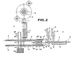
- Fig. 2 is a detailed view of those members of the dobby reading unit and control unit of Fig. 1 which directly cooperate with each other;
- Fig. 3 is a detailed view of the means for controlling the movements of the thrust rods of the reading unit rockers; and
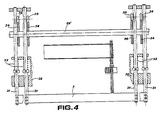
- Fig. 4 is a detailed view of the means for controlling the pressure bars of said reading unit.
- Dobbies are mechanical apparatus by means of which the shed is formed in looms starting from a predetermined fabric design which is transferred in the form of code onto a punched tape, which when read by means of needles controls yoke levers which govern the movement of the heald frames.
- Fig. 1 of the accompanying drawings represents a diagram of a known Hattersley dobby. This diagram shows a reading unit A and a control unit B. The purpose of the reading unit A is to read a punched paper tape C, and comprises reading needles 1, thrust rods 2 oscillating under the control of the needles 1,
pressure bars 3 for engaging and thrusting the rods 2 selected by the needles 1, and control yokes 4 controlled by the rods 2. The purpose of the control unit B is to determine the movements of the heald frames under the control of the reading unit A, and comprises vertical control rods 5 controlled byhorizontal needles 6 subjected to the action of the yokes 4 and ofreturn springs 7 in order to establish and remove the engagement with lifting blades 9 by way of upper end hook portions 8. It also compriseshooks 10 pivoted at 10' to the ends ofyoke levers 11 which in their turn are pivoted at 11' to the centre oftransmission levers 12 which operatelever systems 13 for controlling the heald frames. The vertical rods 5 engage with thehooks 10 in order to raise them and lower them in accordance with commands received from the yokes 4 of the reading unit A. Thehooks 10 engage withfixed knives 14 andmobile knives 15 in order to control theyoke levers 11. Engagement with thefixed knives 14 occurs when the rods 5 raise the hooks under the control of the lifting blades 9 with which the hook portions 8 cooperate. Engagement with themobile knives 14 occurs when the rods 5 do not exert positive force on the hooks. The movements impressed by the rocker levers 11 and transmission levers 12 on thelever systems 13 and thus on the heald frames, leading to the formation of the shed, derive from the combination of these engagements and the law governing the movement of themobile knives 15. - It should be noted that in reality the
fixed knives 14 have only their axes fixed, in the sense that they undergo oscillations about this latter for the purpose of facilitating their engagement with the hooks. In contrast, besides undergoing a similar oscillation about their axes (again to facilitate engagement with the hooks), the mobile knives move such that their axes travel along trajectories in the form of circular arcs c. - It should also be noted that the hooks as a rule are lowered under the positive control of hook lowering plates 16 which ensure disengagement of the hooks from the fixed knives and facilitate their engagement with the mobile knives.
- In the loom dobby according to the invention there is a complete structural separation between the dobby reading unit A and the dobby control unit B. The
horizontal needles 6 which receive their command from the yokes 4 are made completely separate therefrom, the yokes acting on the needles by simple bearing and thrust contact by way of atappet 17. Such an arrangement of the reading and control members, which is very useful from the machine constructional, maintenance and operational aspects, requires a very rigorous guide for the yokes 4. This guide shown in Fig. 2, comprises a fixed support 18 containing cylindrical bores in whichpins 19 rigidly fixed to the yokes 4 slide in a precisely guided manner. The support 18 comprisesslots 20 for freely housing the thrust rods 2 pivoted at 2' to the yokes 4, and a precisely flat front resting surface 21 for the yokes 4 (which engage it by way of theirrear surfaces 22, also rigorously flat, under the action of theneedles 6 pressed by the springs 7). In this manner, the yokes 4 are guided in a rigorous manner both during their horizontal movements and into their rest position, as is essential for proper operation of the dobby. In particular, correct horizontal movement of the rockers 4 is essential for exact control of theneedles 6 by thetappet 17, because of the fact that in the arrangement according to the invention there is no longer the continuity characteristic of conventional machines between the needles and rockers, and in addition a precise rest position for the rockers 4 is essential for correct vertical sliding of the rods 5 in the respective seats 6' of theneedles 6 when said rods receive commands from the lifting blades 9 (in order to prevent friction or forcing). - In the arrangement described and illustrated, the thrust needles 2 are controlled on the one hand by needles 1 which under the action of springs 1' cooperate with the coded design on the punched paper tape C mobile on the roller R, and on the other hand by a
rake member 23 mobile along a rigorously vertical trajectory imposed byguides 24 and controlled by the lever system shown in Fig. 3, which engages its lug 25 (Figs. 2 and 3). The lever system for controlling therake member 23 comprises abent lever 26 pivoted on a fixedpin 27 and having one end hinged to thelug 25 and the other end controlled by a cam 28 (with a shaft 28') against which it is urged into contact by aspring 29 by way of acam follower 30. - Finally, Fig. 4 shows the control means for the
pressure bars 3 which control the thrust rods 2 of the dobby reading unit. - These means comprise
pins 31 fixed to the ends of thebars 3 and axially slidable infixed guides 32 against the action ofreturn springs 33 and under the control ofdisc cams 34 acting onrollers 35 mounted on thepins 31 and rotatable about axes transverse to the axes of saidpins 31. Thedisc cams 34 are controlled by the same shaft 28' which controls thecam 28 which operates therake member 23 for the thrust rods 2.
Claims (3)
Priority Applications (1)
| Application Number | Priority Date | Filing Date | Title |
|---|---|---|---|
| AT82106968T ATE18267T1 (en) | 1981-08-06 | 1982-08-02 | READING DEVICE FOR THE DOBBY OF A LOOPPING MACHINE. |
Applications Claiming Priority (2)
| Application Number | Priority Date | Filing Date | Title |
|---|---|---|---|
| IT2341181 | 1981-08-06 | ||
| IT23411/81A IT1137823B (en) | 1981-08-06 | 1981-08-06 | IMPROVEMENTS IN THE BODIES OF THE DRAFT READING GROUP FOR WEAVING FRAMES |
Publications (3)
| Publication Number | Publication Date |
|---|---|
| EP0071940A2 EP0071940A2 (en) | 1983-02-16 |
| EP0071940A3 EP0071940A3 (en) | 1983-06-08 |
| EP0071940B1 true EP0071940B1 (en) | 1986-02-26 |
Family
ID=11206851
Family Applications (1)
| Application Number | Title | Priority Date | Filing Date |
|---|---|---|---|
| EP82106968A Expired EP0071940B1 (en) | 1981-08-06 | 1982-08-02 | Loom dobby reading unit |
Country Status (7)
| Country | Link |
|---|---|
| US (1) | US4471814A (en) |
| EP (1) | EP0071940B1 (en) |
| JP (1) | JPS5841928A (en) |
| AT (1) | ATE18267T1 (en) |
| DE (1) | DE3269384D1 (en) |
| ES (1) | ES514682A0 (en) |
| IT (1) | IT1137823B (en) |
Families Citing this family (2)
| Publication number | Priority date | Publication date | Assignee | Title |
|---|---|---|---|---|
| JPH0497169U (en) * | 1991-01-21 | 1992-08-21 | ||
| CN103334222A (en) * | 2013-07-02 | 2013-10-02 | 浙江奇汇电子提花机有限公司 | Double acting two-cam oscillating bar transmission mechanism for electronic jacquard machine |
Family Cites Families (7)
| Publication number | Priority date | Publication date | Assignee | Title |
|---|---|---|---|---|
| CH407900A (en) * | 1963-05-24 | 1966-02-15 | Kaiser Kg Johann | Pre-needling apparatus for double-stroke shaft machines |
| DE1535278A1 (en) * | 1966-04-09 | 1969-07-31 | Alfred Weber | Double stroke dobby |
| JPS4528611Y1 (en) * | 1966-08-02 | 1970-11-04 | ||
| US3848643A (en) * | 1971-03-10 | 1974-11-19 | Staeubli Ag | Reading mechanism of a dobby |
| FR2367132A1 (en) * | 1976-10-11 | 1978-05-05 | Staubli Sa Ets | Heald frame selector - having interposer connected to selector needles by tuning fork whose shanks are pivoted universally and articulated to needles |
| FR2406012A1 (en) * | 1977-10-14 | 1979-05-11 | Staubli Sa Ets | TRAINING DEVELOPMENTS FOR THE TEXTILE INDUSTRY |
| FR2449147A1 (en) * | 1979-02-13 | 1980-09-12 | Staubli Sa Ets | IMPROVEMENTS ON RATIERES FOR CROWD FORMATION ON WEAVING |
-
1981
- 1981-08-06 IT IT23411/81A patent/IT1137823B/en active
-
1982
- 1982-08-02 DE DE8282106968T patent/DE3269384D1/en not_active Expired
- 1982-08-02 AT AT82106968T patent/ATE18267T1/en not_active IP Right Cessation
- 1982-08-02 EP EP82106968A patent/EP0071940B1/en not_active Expired
- 1982-08-03 ES ES514682A patent/ES514682A0/en active Granted
- 1982-08-05 US US06/405,361 patent/US4471814A/en not_active Expired - Fee Related
- 1982-08-06 JP JP57137177A patent/JPS5841928A/en active Pending
Also Published As
| Publication number | Publication date |
|---|---|
| EP0071940A3 (en) | 1983-06-08 |
| JPS5841928A (en) | 1983-03-11 |
| DE3269384D1 (en) | 1986-04-03 |
| ES8307940A1 (en) | 1983-08-01 |
| IT8123411A0 (en) | 1981-08-06 |
| ATE18267T1 (en) | 1986-03-15 |
| IT1137823B (en) | 1986-09-10 |
| ES514682A0 (en) | 1983-08-01 |
| EP0071940A2 (en) | 1983-02-16 |
| US4471814A (en) | 1984-09-18 |
Similar Documents
| Publication | Publication Date | Title |
|---|---|---|
| US5115838A (en) | Drive system for the knife grids of a double-lift jacquard machine | |
| US4461325A (en) | Electromagnetic device for controlling dobbies and other weaving systems | |
| US4544000A (en) | Synchronized rotating dobby for weaving looms | |
| EP0071940B1 (en) | Loom dobby reading unit | |
| EP0525862B1 (en) | Improvements in a high-speed rotary dobby | |
| US4182380A (en) | Dobbies for weaving looms | |
| US3724510A (en) | A dobby | |
| US4386631A (en) | Negative double lift dobby machine | |
| US3285291A (en) | Drive-mechanism in double lift dobbies | |
| EP0072486B1 (en) | Improvements in loom dobby control units | |
| US4534385A (en) | Leveling device for weaving mechanisms incorporating cams of the negative type | |
| US3951176A (en) | Hook connecting apparatus in a chain disc-type dobby machine | |
| US3057379A (en) | Dobbies | |
| US4326562A (en) | Dobbies for forming the shed on weaving looms | |
| EP0071943B1 (en) | Play taking-up means in loom dobby control units | |
| US2751938A (en) | Dougle lift shedding motion | |
| US4465107A (en) | Means for controlling knife oscillations and hook movements in a loom dobby | |
| KR0139102B1 (en) | Double lift dobby machine with pulled balance levers for looms | |
| US3851675A (en) | Positive dobby | |
| US4187886A (en) | Dobby for the formation of the shed on looms | |
| GB1559420A (en) | Pattern card reading device for the control of a machine | |
| US2815044A (en) | Double lift dobby | |
| US4474221A (en) | Positive dobby machine | |
| US4197881A (en) | Devices for controlling the heddles of a loom | |
| EP0084570B1 (en) | Positive dobby machine |
Legal Events
| Date | Code | Title | Description |
|---|---|---|---|
| PUAI | Public reference made under article 153(3) epc to a published international application that has entered the european phase |
Free format text: ORIGINAL CODE: 0009012 |
|
| AK | Designated contracting states |
Designated state(s): AT BE CH DE FR GB LI LU NL SE |
|
| PUAL | Search report despatched |
Free format text: ORIGINAL CODE: 0009013 |
|
| AK | Designated contracting states |
Designated state(s): AT BE CH DE FR GB LI LU NL SE |
|
| 17P | Request for examination filed |
Effective date: 19831118 |
|
| GRAA | (expected) grant |
Free format text: ORIGINAL CODE: 0009210 |
|
| AK | Designated contracting states |
Designated state(s): AT BE CH DE FR GB LI LU NL SE |
|
| REF | Corresponds to: |
Ref document number: 18267 Country of ref document: AT Date of ref document: 19860315 Kind code of ref document: T |
|
| REF | Corresponds to: |
Ref document number: 3269384 Country of ref document: DE Date of ref document: 19860403 |
|
| ET | Fr: translation filed | ||
| PG25 | Lapsed in a contracting state [announced via postgrant information from national office to epo] |
Ref country code: LU Free format text: LAPSE BECAUSE OF NON-PAYMENT OF DUE FEES Effective date: 19860831 |
|
| PLBI | Opposition filed |
Free format text: ORIGINAL CODE: 0009260 |
|
| 26 | Opposition filed |
Opponent name: W. SCHLAFHORST & CO. Effective date: 19861011 |
|
| NLR1 | Nl: opposition has been filed with the epo |
Opponent name: W. SCHLAFHORST & CO. |
|
| PLBN | Opposition rejected |
Free format text: ORIGINAL CODE: 0009273 |
|
| STAA | Information on the status of an ep patent application or granted ep patent |
Free format text: STATUS: OPPOSITION REJECTED |
|
| 27O | Opposition rejected |
Effective date: 19880827 |
|
| NLR2 | Nl: decision of opposition | ||
| PGFP | Annual fee paid to national office [announced via postgrant information from national office to epo] |
Ref country code: SE Payment date: 19890630 Year of fee payment: 8 |
|
| PGFP | Annual fee paid to national office [announced via postgrant information from national office to epo] |
Ref country code: LU Payment date: 19890705 Year of fee payment: 8 |
|
| PGFP | Annual fee paid to national office [announced via postgrant information from national office to epo] |
Ref country code: AT Payment date: 19890711 Year of fee payment: 8 |
|
| PGFP | Annual fee paid to national office [announced via postgrant information from national office to epo] |
Ref country code: BE Payment date: 19890712 Year of fee payment: 8 |
|
| PGFP | Annual fee paid to national office [announced via postgrant information from national office to epo] |
Ref country code: GB Payment date: 19890731 Year of fee payment: 8 |
|
| PGFP | Annual fee paid to national office [announced via postgrant information from national office to epo] |
Ref country code: NL Payment date: 19890831 Year of fee payment: 8 |
|
| PGFP | Annual fee paid to national office [announced via postgrant information from national office to epo] |
Ref country code: DE Payment date: 19900724 Year of fee payment: 9 |
|
| PGFP | Annual fee paid to national office [announced via postgrant information from national office to epo] |
Ref country code: FR Payment date: 19900727 Year of fee payment: 9 |
|
| PG25 | Lapsed in a contracting state [announced via postgrant information from national office to epo] |
Ref country code: GB Effective date: 19900802 Ref country code: AT Effective date: 19900802 |
|
| PG25 | Lapsed in a contracting state [announced via postgrant information from national office to epo] |
Ref country code: SE Effective date: 19900803 |
|
| PGFP | Annual fee paid to national office [announced via postgrant information from national office to epo] |
Ref country code: CH Payment date: 19900829 Year of fee payment: 9 |
|
| PG25 | Lapsed in a contracting state [announced via postgrant information from national office to epo] |
Ref country code: BE Effective date: 19900831 |
|
| BERE | Be: lapsed |
Owner name: FIMTESSILE FABBRICA ITALIANA MACCHINARIO TESSILE Effective date: 19900831 |
|
| PG25 | Lapsed in a contracting state [announced via postgrant information from national office to epo] |
Ref country code: NL Effective date: 19910301 |
|
| GBPC | Gb: european patent ceased through non-payment of renewal fee | ||
| NLV4 | Nl: lapsed or anulled due to non-payment of the annual fee | ||
| PG25 | Lapsed in a contracting state [announced via postgrant information from national office to epo] |
Ref country code: LI Effective date: 19910831 Ref country code: CH Effective date: 19910831 |
|
| PG25 | Lapsed in a contracting state [announced via postgrant information from national office to epo] |
Ref country code: FR Effective date: 19920430 |
|
| REG | Reference to a national code |
Ref country code: CH Ref legal event code: PL |
|
| PG25 | Lapsed in a contracting state [announced via postgrant information from national office to epo] |
Ref country code: DE Effective date: 19920501 |
|
| REG | Reference to a national code |
Ref country code: FR Ref legal event code: ST |
|
| EUG | Se: european patent has lapsed |
Ref document number: 82106968.9 Effective date: 19910410 |