EP0071905B1 - Adjustable reflector with imperforate reflective membrane - Google Patents
Adjustable reflector with imperforate reflective membrane Download PDFInfo
- Publication number
- EP0071905B1 EP0071905B1 EP82106891A EP82106891A EP0071905B1 EP 0071905 B1 EP0071905 B1 EP 0071905B1 EP 82106891 A EP82106891 A EP 82106891A EP 82106891 A EP82106891 A EP 82106891A EP 0071905 B1 EP0071905 B1 EP 0071905B1
- Authority
- EP
- European Patent Office
- Prior art keywords
- membrane
- housing
- reflector according
- rod
- evacuation
- Prior art date
- Legal status (The legal status is an assumption and is not a legal conclusion. Google has not performed a legal analysis and makes no representation as to the accuracy of the status listed.)
- Expired
Links
- 239000012528 membrane Substances 0.000 title claims description 128
- 239000012530 fluid Substances 0.000 claims description 15
- 238000004891 communication Methods 0.000 claims description 11
- 239000003990 capacitor Substances 0.000 claims description 7
- 230000005291 magnetic effect Effects 0.000 claims description 6
- 230000001105 regulatory effect Effects 0.000 claims description 6
- 239000004020 conductor Substances 0.000 claims 1
- 230000007246 mechanism Effects 0.000 description 12
- 230000008878 coupling Effects 0.000 description 8
- 238000010168 coupling process Methods 0.000 description 8
- 238000005859 coupling reaction Methods 0.000 description 8
- 230000002093 peripheral effect Effects 0.000 description 8
- 230000004913 activation Effects 0.000 description 4
- 229910052751 metal Inorganic materials 0.000 description 4
- 239000002184 metal Substances 0.000 description 4
- 230000005355 Hall effect Effects 0.000 description 3
- 235000014676 Phragmites communis Nutrition 0.000 description 3
- 230000009849 deactivation Effects 0.000 description 3
- 239000010408 film Substances 0.000 description 3
- 238000004519 manufacturing process Methods 0.000 description 3
- 239000000853 adhesive Substances 0.000 description 2
- 230000001070 adhesive effect Effects 0.000 description 2
- 230000032683 aging Effects 0.000 description 2
- 229910052782 aluminium Inorganic materials 0.000 description 2
- XAGFODPZIPBFFR-UHFFFAOYSA-N aluminium Chemical compound [Al] XAGFODPZIPBFFR-UHFFFAOYSA-N 0.000 description 2
- 230000008901 benefit Effects 0.000 description 2
- 239000011248 coating agent Substances 0.000 description 2
- 238000000576 coating method Methods 0.000 description 2
- 230000005670 electromagnetic radiation Effects 0.000 description 2
- 238000001465 metallisation Methods 0.000 description 2
- 239000004033 plastic Substances 0.000 description 2
- 230000004044 response Effects 0.000 description 2
- 239000007787 solid Substances 0.000 description 2
- 239000005041 Mylar™ Substances 0.000 description 1
- 230000003213 activating effect Effects 0.000 description 1
- 230000002411 adverse Effects 0.000 description 1
- 239000011324 bead Substances 0.000 description 1
- 230000008602 contraction Effects 0.000 description 1
- 230000006866 deterioration Effects 0.000 description 1
- 238000011161 development Methods 0.000 description 1
- 230000018109 developmental process Effects 0.000 description 1
- 239000000428 dust Substances 0.000 description 1
- 239000013536 elastomeric material Substances 0.000 description 1
- 230000007613 environmental effect Effects 0.000 description 1
- 239000003302 ferromagnetic material Substances 0.000 description 1
- 230000001939 inductive effect Effects 0.000 description 1
- 239000000463 material Substances 0.000 description 1
- 239000011104 metalized film Substances 0.000 description 1
- 238000000034 method Methods 0.000 description 1
- 239000012811 non-conductive material Substances 0.000 description 1
- 230000005855 radiation Effects 0.000 description 1
- 230000000717 retained effect Effects 0.000 description 1
- 238000012360 testing method Methods 0.000 description 1
- 238000013022 venting Methods 0.000 description 1
- 238000003466 welding Methods 0.000 description 1
Images


Classifications
-
- G—PHYSICS
- G02—OPTICS
- G02B—OPTICAL ELEMENTS, SYSTEMS OR APPARATUS
- G02B26/00—Optical devices or arrangements for the control of light using movable or deformable optical elements
- G02B26/08—Optical devices or arrangements for the control of light using movable or deformable optical elements for controlling the direction of light
- G02B26/0816—Optical devices or arrangements for the control of light using movable or deformable optical elements for controlling the direction of light by means of one or more reflecting elements
- G02B26/0825—Optical devices or arrangements for the control of light using movable or deformable optical elements for controlling the direction of light by means of one or more reflecting elements the reflecting element being a flexible sheet or membrane, e.g. for varying the focus
-
- F—MECHANICAL ENGINEERING; LIGHTING; HEATING; WEAPONS; BLASTING
- F24—HEATING; RANGES; VENTILATING
- F24S—SOLAR HEAT COLLECTORS; SOLAR HEAT SYSTEMS
- F24S23/00—Arrangements for concentrating solar-rays for solar heat collectors
- F24S23/70—Arrangements for concentrating solar-rays for solar heat collectors with reflectors
- F24S23/71—Arrangements for concentrating solar-rays for solar heat collectors with reflectors with parabolic reflective surfaces
- F24S23/715—Arrangements for concentrating solar-rays for solar heat collectors with reflectors with parabolic reflective surfaces flexible
-
- Y—GENERAL TAGGING OF NEW TECHNOLOGICAL DEVELOPMENTS; GENERAL TAGGING OF CROSS-SECTIONAL TECHNOLOGIES SPANNING OVER SEVERAL SECTIONS OF THE IPC; TECHNICAL SUBJECTS COVERED BY FORMER USPC CROSS-REFERENCE ART COLLECTIONS [XRACs] AND DIGESTS
- Y02—TECHNOLOGIES OR APPLICATIONS FOR MITIGATION OR ADAPTATION AGAINST CLIMATE CHANGE
- Y02E—REDUCTION OF GREENHOUSE GAS [GHG] EMISSIONS, RELATED TO ENERGY GENERATION, TRANSMISSION OR DISTRIBUTION
- Y02E10/00—Energy generation through renewable energy sources
- Y02E10/40—Solar thermal energy, e.g. solar towers
Definitions
- the invention relates to a reflector comprising a hollow housing having top and bottom openings, a flexible, elastic imperforate reflective membrane, coupled over said top opening in a gas-tight manner, base means for covering said bottom opening in a gas-tight manner, evacuation means, coupled to said housing, for creating a partial vacuum in said housing tending to deflect said membrane below a reference plane and into said housing and control means for regulating evacuation of said housing by said evacuation means.
- Reflectors of this general type are used in systems for utilizing solar energy, and for that purpose it is highly advantageous to provide a solar reflector with reliable means for exactly adjusting the focal length of the reflector.
- a mirror device which is to be used for focusing a laser beam and tracking a target by the focused beam.
- the circular, and initially plane mirror is brought into a curved shape either by applying a vacuum to the airtight cavity covered by a resilient mirror plate, or by nuts and bolts devices which are pivotally connected to the back of the mirror plate fixedly secured at its periphery on a frame, the nuts and bolts devices being used for displacing the middle area of the mirror plate.
- the mirror consists of a reflective film mounted on a frame in that way that the volume enclosed thereby can be evacuated by pump means so that the reflective film is given a curved concave shape.
- the film is preshaped by a regular pattern of radially extending thickened seams.
- the main object of the present invention is to provide a reflector of electromagnetic radiation with an easily and accurately adjustable focal length
- a reflector with a hollow housing having top and bottom openings, a flexible, elastic imperforate reflective membrane, coupled over said top openings in a gas-tight manner, base means for covering said bottom opening in a gas-tight manner, evacuation means, coupled to said housing, for creating a partial vacuum in said housing tending to deflect said membrane below a reference plane and into said housing and control means for regulating evacuation of said housing by said evacuation means.
- adjustment means coupled to said base means, for supporting and adjustably positioning said control means in said housing at a location corresponding to a predetermined deflection of said membrane below said reference plane, said adjustment means comprising a rod movably mounted in an aperture in said base means and lock means for releasably securing said rod in a predetermined position, said rod having at least a portion of said control means for regulating evacuation of said housing at an end thereof for coacting with said reflective membrane.
- a reflector according to the present invention is lightweight and inexpensive to manufacture, install and maintain, and can be provided with an imperforate reflective membrane which is unobstructed.
- a further advantage of the present invention is that such reflector can be adjusted by unskilled personnel.
- a reflector comprising a hollow housing having top and bottom openings with a flexible, elastic, imperforate reflective membrane coupled over the top opening in a gas-tight manner and a base covering the bottom opening in a gas-tight manner.
- a tube is mounted in the base with an internal passageway and upper end in the housing.
- Evacuation means in fluid communication with the internal passageway, is provided for creating a partial vacuum in the housing tending to deflect the membrane below a reference plane and into the housing.
- a membrane contact surface is provided on the upper end of the tube and surrounds an orifice, which orifice is in fluid communication with the internal passageway. The contact surface is positioned at a distance below the reference plane corresponding to a predetermined deflection of the membrane.
- the focal length may be simply and easily adjusted by unskilled personnel by manipulating the adjustment means. Since the adjustment means is coupled to the base of the reflector, it is readily accessible and does not interfere with the reflective characteristics of the membrane. Since the membrane is imperforate, the focal length will not be adversely affected by environmental conditions such as high winds, rain and dust.
- the membrane With a control arrangement comprising a membrane contact surface surrounding an orifice at the upper end of the tube, the membrane is simply and accurately deflected to its predetermined configuration. Since the contact surface is positioned a distance below the reference plane corresponding to the predetermined deflection of the membrane, the membrane will, upon reaching the predetermined deflection, engage the contact surface and terminate evacuation of the housing to maintain the membrane in the predetermined configuration.
- the adjustment means can comprise a threaded rod.
- the base means may comprise a rigid plate or a flexible membrane.
- the control may be provided by a mechanical arrangement, and electric limit switch, a light source and sensor, a variable capacitor or inductor arrangement, or a magnetic field sensing arrangement.
- top and bottom are intended to facilitate the description of the reflector. Thus, such terms are merely illustrative of the reflector and are not intended to limit the reflector to any specific orientation.
- the reflector 20 in accordance with the present invention, as illustrated, comprises a hollow housing 22 having a top opening 24 and a bottom opening 26. Top opening 24 is covered in a gas-tight manner by a flexible, elastic, imperforate reflective membrane 28. Bottom opening 26 is covered in a gas-tight manner by a rigid base 30.
- An evacuation assembly 32 is coupled to housing 22 for creating a partial vacuum within the housing.
- a control device 34 regulates the evacuation of housing 22 by evacuation assembly 32.
- the control device is supported and adjustably positioned within housing 22 at a location corresponding to a predetermined deflection of the membrane below reference plane A by an adjustment mechanism 36.
- the focal length of the reflector is varied by varying the amount of deflection of the membrane within the housing.
- the reflector can be employed for solar radiation, as well as radar, television signals and other electromagnetic radiation.
- Housing 22 is advantageously a right cylindrical tube with openings 24, 26 oriented in planes perpendicular to the axis of the cylindrical housing. Openings 24, 26 as illustrated are annular, although they could be rectangular with the housing having a rectangular cross section.
- Membrane 28 has a reflective coating on its exterior surface 29, which coating can be aluminum by, for example, forming the membrane from aluminized Mylar g.
- the membrane is larger in diameter than top opening 24 such that the peripheral portion extends past and completely closes the opening.
- the thickness of membrane 28 can be between about 1.27 p (0.0005 inch) and about 5.08 ⁇ (0.002 inch).
- Coupling mechanism 40 attaches membrane 28 to housing 22 in a gas-tight manner.
- This coupling mechanism comprises an annular groove 42 formed in the top surface of housing 22 concentrically about top opening 24.
- Peripheral portion 44 of membrane 28 is received in groove 42 and is secured therein by an attaching ring 46.
- Attaching ring 46 is received over peripheral portion 44 and within annular groove 42.
- peripheral portion 44 is interposed between annular groove 42 and attaching ring 46 to secure membrane 28 to housing 22 in a gas-tight manner.
- membrane 28 is initially stretched when it is coupled to housing 22 such that in its undisturbed condition, it lies flat in reference plane A as illustrated in Fig. 2.
- Reference plane A essentially corresponds to the plane containing top opening 24 in housing 22.
- a plurality of fasteners can be employed to rigidly secure attaching ring 46 to housing 22, if necessary.
- Base 30 in the first embodiment, comprises a rigid, solid disc-shaped metal plate 48 having an internally threaded aperture 50 in the center thereof.
- the peripheral portion of plate 48 is secured in a suitable manner, such as by adhesive, to the lower surface of housing 22 to seal bottom opening 26 in a gas-tight manner.
- the coupling of plate 48 to housing 22 can also involve the use of conventional seals, fasteners or welding techniques.
- adjustment mechanism 36 comprises a rod 52 which is threaded externally on the lower portion thereof and which is threadably received within threaded aperture 50 in plate 48.
- Rod 52 has an internal passageway 54 extending along the length thereof.
- a lock nut 56 is threaded on the lower portion of rod 52 below plate 48 to secure rod 52 in a desired position relative to base 30 and to reference plane A.
- Control device 34 mounted on the top of rod 52 comprises a cup-shaped valve 58 with a generally semispherical interior surface 60 defining a generally semispherical interior volume of the valve.
- the uppermost portion of valve 58 comprises an annular membrane contact surface 62 which surrounds an orifice 64.
- Orifice 64 is aligned with and in fluid communication with passageway 54 within rod 52 and with the interior of housing 22 between membrane 28 and base 30.
- Valve 58 may be formed of metal or plastic. With a valve formed of metal, contact surface 62 can have a resilient, annular gasket 66 of elastomeric material thereon.
- Evacuation assembly 32 comprises a fluid line 68 coupled in fluid communication with internal passageway 54 in rod 52, a valve 70 located in line 68 and a pump 72 located in line 68 downstream of valve 70.
- Valve 70 can be a needle valve or merely a restrictor tube located in fluid line 68 to limit the air flow rate into and out of housing 22.
- Membrane 28 is deflected inwardly of housing 22 by activating pump 72, thereby creating a partial vacuum in the interior of housing 22. Fluid is withdrawn from the housing interior through orifice 64 and passageway 54 causing membrane 28 to be drawn into the housing and to assume a curved configuration. Membrane 28 will continue to be drawn until it reaches the desired depth d where the lowermost surface of membrane 28 engages contact surface 62 terminating fluid communication between the housing interior and passageway 54 and halting further deflection of membrane 28. The partial vacuum created within the interior of housing 22 and within passageway 54 will maintain membrane 28 in the proper deflected configuration.
- Figs. 5-7 illustrate a second embodiment of the present invention having a modified form of base 30'.
- base 30' comprises a second flexible, elastic membrane 74 which is coupled in a gas-tight manner over bottom opening 26 in a manner similar to coupling mechanism 40.
- Membrane 74 need not be reflective.
- Rod 52 is supported in an internally threaded sleeve 76.
- Lock nut 78 is internally threaded and receives the threaded portion of rod 52 to lock rod 52 to sleeve 76 in a desired position.
- Sleeve 76 is coupled to housing 22 adjacent the center of base 30' by a plurality of elongated members in the form of spokes 80 having bent ends received in apertures 82 in an annular flange 84 extending from sleeve 76.
- the ends of spokes 80 remote from flange 84 are rigidly coupled to housing brackets 86.
- Brackets 86 are rigidly secured to housing 22 by bolts 88.
- the distal ends of spokes 80 are threaded, received in bores in brackets 86 and secured therein by nuts 90.
- the bent ends of spokes 80 have enlarged beads 92 to secure them in apertures 82.
- Rod 52 extends through an aperture 94 in membrane 74.
- the surface of aperture 94 forms a seal with the periphery of rod 52 in both the rest and deflected configurations of the membrane.
- the operation of the second embodiment is similar to that of the first embodiment. Thus, the operation of the second embodiment is not discussed in detail. However, it should be noted that in the second embodiment the second membrane 74 is deflected into housing 22 along with the reflective membrane 28, as illustrated in Fig. 6.
- evacuation assembly 32 comprises a tube 96 fixedly mounted in an aperture 98 in base 30.
- Fluid line 68 with valve 70 and pump 72 are coupled in fluid communication with tube 96 and therethrough with the interior of housing 22.
- the control device 134 in this embodiment comprises an electrical limit switch.
- the limit switch has contacts 100, 102 which are normally biased to an open electrical condition, as illustrated in Fig. 8.
- Contacts 100, 102 are electrically coupled through wires 104, terminals 106 and leads 108 to a conventional electrical control circuit 110.
- Electrical control circuit 110 is suitably coupled to vacuum pump 72 to regulate activation and deactivation of pump 72 in response to the opening and closing of contacts 100, 102.
- contacts 100, 102 are closed, pump 72 is deactivated to stop evacuation of housing 22 and to halt deflection of membrane 28, as illustrated in Fig. 9.
- the limit switch may also be one having internal contacts, allowing an operational logic reversed to the one described above.
- control circuit 110 may regulate opening and closing of valve 70 instead of activation and deactivation of pump 72 to control the partial vacuum created within the housing 22, as indicated by the dashed lines.
- Adjustment mechanism 36 comprises an externally threaded rod or bolt 112 received in internally threaded aperture 50 in base 30.
- the electrical limit switch control device 134 is mounted on the top end of bolt 112 such that the distance at which control device 134 is located below reference plane A may be easily adjusted by threading bolt 112 into or out of aperture 50. In this manner, control device 134 may be positioned below reference plane A a distance corresponding to the predetermined or desired deflection of the membrane within housing 22 below reference plane A.
- a lock nut 56 is threaded on the lower end of bolt 112 to secure bolt 112, and thereby electrical limit switch device, in a desired position relative to reference plane A and base 30.
- the wires 104 are provided with sufficient slack to permit adjustment of bolt 112 within aperture 50.
- bolt 112 is adjusted to locate electrical limit switch control device 134 at a distance below reference plane A corresponding to a predetermined deflection of the membrane within housing 22.
- the evacuation pump is activated to develop a partial vacuum within housing 22 to commence deflection of the membrane below reference plane A.
- control circuit 110 Upon sensing closing of contacts 100, 102, control circuit 110 deactivates evacuation pump 72 or closes valve 70 to stop evacuation of the housing interior. The partial vacuum within housing 22 is maintained to retain reflective membrane 28 in the desired deflected configuration.
- the control device 234 for regulating deflection of reflective membrane 28 below reference plane A comprises a light source 114 and a light sensor 116. Both the light source and the light sensor are mounted on the top of control device 234. A reflective surface can be provided on all or on only a portion of the bottom surface of membrane 28.
- Light source 114 is focused on the center of membrane 28 such that when membrane 28 is deflected to its predetermined deflection, the light (indicated by arrow 118) from light source 114 is reflected off the bottom of the membrane and onto light sensor 116, as illustrated in Fig. 11.
- the light (indicated by arrow 120) reflects on an off-center position on membrane 28 so that the light is not directed onto the light sensor 116.
- Light source 114 and light sensor 116 are electrically coupled through wires 104, terminals 106 and leads 108 to a suitable control circuit 110. When light is not sensed by sensor 116, no electrical signal is produced thereby. However, when light is sensed in sensor 116, an electrical signal is transmitted to control circuit 110. The presence or absence of an electrical signal from sensor 116 regulates deactivation and activation of pump 72 or regulates closing and opening of valve 70 through control circuit 110.
- light control device 234 is adjustably mounted within housing 22 to a position corresponding to a predetermined deflection of membrane 28 below reference plane A. This position will be somewhat below the lowermost portion of membrane 28 in its deflected configuration due to the nature of the operation of the light control device 234.
- Pump 72 is initially activated to create a partial vacuum in housing 22 to deflect membrane 28 below reference plane A and into housing 22. Light is emitted from light source 114 against the inner surface of membrane 28 to continually test the position of membrane 28. When the membrane is still above its predetermined position, the light, as indicated by arrow 120, is deflected off membrane 28 to a position remote from light sensor 116 such that no light is sensed thereby and no electrical signal is sent to control circuit 110.
- pump 72 continues to create a partial vacuum through tube 96.
- membrane 28 has been deflected to its predetermined position, light from source 114 is deflected, as indicated by arrow 118, to light sensor 116.
- Light sensor 116 then produces an electrical signal upon sensing the light reflected off the membrane from light source 114, which electrical signal is sent to control circuit 110.
- This electrical signal causes circuit 110 to deactivate pump 72 or close valve 70 to halt evacuation of housing 22 and halt deflection of reflective membrane 28. Since the partial vacuum is maintained within housing 22, the reflective membrane 28 will be retained in its predetermined deflected position, as illustrated in Fig. 11.
- a fifth embodiment of the present invention is illustrated in Figs. 12 and 13.
- This fifth embodiment employs a capacitive sensor control device 334 to regulate deflection of reflective membrane 28.
- the capacitive device comprises two electrically conductive capacitor plates 122, 124.
- the upper capacitor plate 122 is bonded or otherwise attached at a single central location thereof to the center of the internal surface of reflective membrane 28. Attachment of plate 122 in only a single location permits plate 122 to remain substantially planar during deflection of membrane 28.
- the metallized film on reflective membrane 28 cannot reliably be employed as a sensor plate since the metallization weathers and deteriorates rapidly. The weathering and deterioration of the metallization would vary the capacitance value obtained at a given deflection of the membrane, thereby creating control and accuracy problems.
- the lower aluminum plate 124 is fixed to bolt 112 of adjustment mechanism 36 by a suitable device, such as a screw fastener.
- bolt 112 is made of electrically non-conductive material, or the plate must be electrically insulated from bolt 112, if bolt 112 is formed of metal.
- Plates 122, 124 are electrically coupled to electrical control circuit 110 through wires 104, terminals 106 and leads 108.
- the capacitor can, for example, be part of a resonant circuit in control circuit 110, the frequency of which varies with capacitance. This variation in frequency can then be used by control circuit 110 to activate and deactivate pump 72 or to open and close valve 70 in response to the variance in capacitance.
- the reflector is in the rest position, as illustrated in Fig. 12.
- bolt 112 Prior to activation of pump 72, bolt 112 is adjusted to locate plate 124 at a distance below reference plane A corresponding to the predetermined deflection d of membrane 28 below reference plane A.
- An electrical potential is developed across plates 122, 124 and pump 72 is activated to create a partial vacuum in the interior of housing 22 through tube 96.
- the electrical capacitance between plates 122, 124 increases markedly.
- control circuit 110 deactivates pump 72 or closes valve 70 halting evacuation of housing 22 and deflection of membrane 28.
- the partial vacuum is maintained in housing 22 to retain the membrane in its desired position.
- control device 434 can take the form of a proximity sensor 126 such as a device that detects the proximity of a magnetic field, such as a magnetic reed switch or a solid state Hall effect sensor.
- sensor 126 can be a coil having known inductive characteristics.
- a small permanent magnet 128 is bonded or otherwise fixedly attached to the center of the interior surface of reflective membrane 28.
- the magnetic proximity sensor produces an electrical signal which varies either continuously, in the case of a Hall effect device, or stepwise in the case of a reed switch, depending upon the proximity of a magnetic field thereto.
- the electrical signal produced by sensor 126 varies depending upon the distance of magnet 128 therefrom.
- sensor 126 is a coil, it cooperates with a core of conventional ferromagnetic material the proximity of which to the coil varies its inductance.
- the coil as with the capacitor, can form part of a resonant circuit in control circuit 110.
- Wires 104, terminals 106 and leads 108 electrically couple sensor 126 to electrical control circuit 110 which is coupled to pump 72 to activate and deactivate the pump or which is coupled to valve 70 to open and close the valve.
- Proximity sensor 126 is mounted on the top end of bolt 112 of adjustment mechanism 36 to permit adjustment of sensor 126 to a location below reference plane A corresponding to a predetermined deflection of the membrane. In this manner, the focal length for reflector 20 may be varied.
- sensor 126 is located in a position within housing 22 corresponding to the desired deflection d of membrane 28.
- Pump 72 is then activated to create a partial vacuum causing deflection of reflective membrane 28 within housing 22.
- membrane 28 reaches the desired deflected configuration, such configuration is sensed by sensor 126, by sensing the position of magnet or core 128, and sensor 126 sends a particular electrical signal to control circuit 110. This signal causes control circuit to deactivate pump 72 or close valve 70.
- the partial vacuum is maintained within housing 22 to retain membrane 28 in the reflective configuration.
- FIG. 15 A seventh embodiment in accordance with the present invention is illustrated in Fig. 15 in which the reflective membrane 28 is releasably coupled to housing 22.
- the coupling mechanism 40 of the previous embodiments is replaced by detachable coupling mechanism 130 which comprises rigid inner and outer annular rim members 132, 139 formed of relatively inexpensive materials such as plastic or masonite, and springs 136.
- Inner and outer rim members 132, 139 are fixed to the inner and outer surfaces, respectively, of the peripheral portion 138 of membrane 28 and are axially offset such that the outer rim member extends above the inner rim member and the membrane.
- Inner rim member 132 is fixed to the membrane inner surface by double sided tape or adhesive 140.
- Outer rim member 139 is fixed to peripheral portion 138 and to inner rim member 132 by a plurality of suitable fasteners, such as staples 142.
- Springs 136 are formed with hooked ends and are attached at their upper ends over the upper edge of outer rim member 139 and at their lower ends over the lower edge of housing 22.
- Plate 48 forming the base 30 for the reflector is spaced upwardly from bottom opening 26 to provide a lip at opening 26 to facilitate the engagement of the lower hooked ends of springs 136.
- eight springs are equally spaced about housing 22.
- Membrane 28 is manufactured with rim members 132, 139 prior to mounting on housing 22. Since the membrane is tensioned by springs 136, the membrane need not be tensioned during the attachment of the rim members, thereby simplifying its manufacture.
- the membrane with the rim members secured thereto, is fitted over top opening 24 such that peripheral portion 138 and rim members 132, 139 are located laterally beyond and coaxially with housing 22.
- Spring 136 are then coupled to outer rim member 139 and to the bottom edge of housing 22 to tension membrane 28 over the top edge of the housing and to form a gas-tight seal therebetween.
- the membrane is removed by detaching the springs and then lifting the membrane and rim member assembly from the housing. In this manner, the membrane may be simply and quickly installed and removed from housing 22 to facilitate its replacement without replacing housing 22, and is constantly tensioned to compensate for temperature changes and aging stretch.
- the operation of the seventh embodiment is substantially identical to that of the first-embodiment. Thus, the operation of the seventh embodiment is not discussed in detail.
- FIG. 8-15 Although each of the embodiments of Figs. 8-15 have been illustrated and discussed as having a base 30 comprising a rigid plate 48, such rigid plate may be replaced by the flexible membrane base arrangement illustrated in Figs. 5-7.
- a suitable venting mechanism can be provided to permit the partial vacuum to be relieved within housing 22.
Landscapes
- Engineering & Computer Science (AREA)
- Physics & Mathematics (AREA)
- Sustainable Energy (AREA)
- Life Sciences & Earth Sciences (AREA)
- Optics & Photonics (AREA)
- Sustainable Development (AREA)
- General Physics & Mathematics (AREA)
- Thermal Sciences (AREA)
- Chemical & Material Sciences (AREA)
- Combustion & Propulsion (AREA)
- Mechanical Engineering (AREA)
- General Engineering & Computer Science (AREA)
- Optical Elements Other Than Lenses (AREA)
Description
- The invention relates to a reflector comprising a hollow housing having top and bottom openings, a flexible, elastic imperforate reflective membrane, coupled over said top opening in a gas-tight manner, base means for covering said bottom opening in a gas-tight manner, evacuation means, coupled to said housing, for creating a partial vacuum in said housing tending to deflect said membrane below a reference plane and into said housing and control means for regulating evacuation of said housing by said evacuation means.
- Reflectors of this general type are used in systems for utilizing solar energy, and for that purpose it is highly advantageous to provide a solar reflector with reliable means for exactly adjusting the focal length of the reflector.
- In US-A-3 514776 a mirror device is shown which is to be used for focusing a laser beam and tracking a target by the focused beam. The circular, and initially plane mirror is brought into a curved shape either by applying a vacuum to the airtight cavity covered by a resilient mirror plate, or by nuts and bolts devices which are pivotally connected to the back of the mirror plate fixedly secured at its periphery on a frame, the nuts and bolts devices being used for displacing the middle area of the mirror plate. In US-A-4 033 676 the mirror consists of a reflective film mounted on a frame in that way that the volume enclosed thereby can be evacuated by pump means so that the reflective film is given a curved concave shape. The film is preshaped by a regular pattern of radially extending thickened seams.
- In FR-A-2 402 882, US-A-3 623 796 and DE-A-2 631 551 rather similar devices are shown.
- Though in these known devices it may be possible to deflect the initially plane mirror more or less, thereby giving its outside a concave shape, it would be rather difficult to exactly adapt the mirror to a predetermined curvature and to reliably adjust its focal length.
- Accordingly, the main object of the present invention is to provide a reflector of electromagnetic radiation with an easily and accurately adjustable focal length comprising a reflector with a hollow housing having top and bottom openings, a flexible, elastic imperforate reflective membrane, coupled over said top openings in a gas-tight manner, base means for covering said bottom opening in a gas-tight manner, evacuation means, coupled to said housing, for creating a partial vacuum in said housing tending to deflect said membrane below a reference plane and into said housing and control means for regulating evacuation of said housing by said evacuation means. According to the invention the problem is solved by adjustment means, coupled to said base means, for supporting and adjustably positioning said control means in said housing at a location corresponding to a predetermined deflection of said membrane below said reference plane, said adjustment means comprising a rod movably mounted in an aperture in said base means and lock means for releasably securing said rod in a predetermined position, said rod having at least a portion of said control means for regulating evacuation of said housing at an end thereof for coacting with said reflective membrane.
- A reflector according to the present invention is lightweight and inexpensive to manufacture, install and maintain, and can be provided with an imperforate reflective membrane which is unobstructed.
- A further advantage of the present invention is that such reflector can be adjusted by unskilled personnel.
- The foregoing objects are also basically obtained by providing a reflector comprising a hollow housing having top and bottom openings with a flexible, elastic, imperforate reflective membrane coupled over the top opening in a gas-tight manner and a base covering the bottom opening in a gas-tight manner. A tube is mounted in the base with an internal passageway and upper end in the housing. Evacuation means, in fluid communication with the internal passageway, is provided for creating a partial vacuum in the housing tending to deflect the membrane below a reference plane and into the housing. A membrane contact surface is provided on the upper end of the tube and surrounds an orifice, which orifice is in fluid communication with the internal passageway. The contact surface is positioned at a distance below the reference plane corresponding to a predetermined deflection of the membrane.
- By forming the reflector in this manner, the focal length may be simply and easily adjusted by unskilled personnel by manipulating the adjustment means. Since the adjustment means is coupled to the base of the reflector, it is readily accessible and does not interfere with the reflective characteristics of the membrane. Since the membrane is imperforate, the focal length will not be adversely affected by environmental conditions such as high winds, rain and dust.
- With a control arrangement comprising a membrane contact surface surrounding an orifice at the upper end of the tube, the membrane is simply and accurately deflected to its predetermined configuration. Since the contact surface is positioned a distance below the reference plane corresponding to the predetermined deflection of the membrane, the membrane will, upon reaching the predetermined deflection, engage the contact surface and terminate evacuation of the housing to maintain the membrane in the predetermined configuration.
- Replacement of the reflective membrane is greatly facilitated by employing coupling means with spring means for releasably attaching and tensioning the membrane over the housing top opening. The housing need not be replaced with the membrane resulting in substantial cost savings. Additionally, the constant tension in the membrane caused by the spring means compensates for membrane expansion and contraction resulting from temperature changes and aging and facilitates its manufacture since the membrane need not be tensioned before it is coupled to the housing.
- The adjustment means can comprise a threaded rod. The base means may comprise a rigid plate or a flexible membrane. The control may be provided by a mechanical arrangement, and electric limit switch, a light source and sensor, a variable capacitor or inductor arrangement, or a magnetic field sensing arrangement. Other objects, advantages and salient features of the present invention will become apparent from the following detailed description, which, taken in conjunction with the annexed drawings, discloses preferred embodiments of the present invention.
- As used in this application, the terms "top" and "bottom" are intended to facilitate the description of the reflector. Thus, such terms are merely illustrative of the reflector and are not intended to limit the reflector to any specific orientation.
- Referring to the drawings which form a part of this original disclosure:
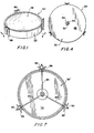
- FIG. 1 is a perspective view of a reflector in accordance with the present invention;
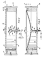
- FIG. 2 is a side elevational view in section taken along lines 2-2 in Fig. 1 showing the reflector in accordance with a first embodiment of the present invention in its rest position before a partial vacuum is created inside the housing;
- FIG. 3 is a side elevational view in section of the reflector of Fig. 2, after a partial vacuum has been created inside the housing to deflect the reflective membrane therein:
- FIG. 4 is a bottom plan view of the reflector of Fig. 2;
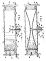
- FIGS. 5 and 6 are views similar to those shown in Figs. 2 and 3, respectively, of a second embodiment of the reflector in accordance with the present invention;
- FIG. 7 is a bottom plan view of the reflector of Figs. 5 and 6;
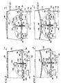
- FIGS. 8 and 9 are partial, side elevational views in section of a third embodiment of the reflector in accordance with the present invention;
- FIGS. 10 and 11 are partial, side elevational views in section of a fourth embodiment of the reflector in accordance with the present invention;
- FIGS. 12 and 13 are partial, side elevational views in section of a fifth embodiment of the reflector in accordance with the present invention;
- FIG. 14 is a partial, side elevational view in section of a sixth embodiment of the reflector in accordance with the present invention; and
- FIG. 15 is a side elevational view in section of a seventh embodiment of the reflector in accordance with the present invention. Detailed Description of the Preferred Embodiments of the Invention
- Referring initially to Figs. 1-4, the
reflector 20 in accordance with the present invention, as illustrated, comprises ahollow housing 22 having a top opening 24 and a bottom opening 26.Top opening 24 is covered in a gas-tight manner by a flexible, elastic, imperforatereflective membrane 28.Bottom opening 26 is covered in a gas-tight manner by arigid base 30. Anevacuation assembly 32 is coupled tohousing 22 for creating a partial vacuum within the housing. Acontrol device 34 regulates the evacuation ofhousing 22 byevacuation assembly 32. The control device is supported and adjustably positioned withinhousing 22 at a location corresponding to a predetermined deflection of the membrane below reference plane A by anadjustment mechanism 36. The focal length of the reflector is varied by varying the amount of deflection of the membrane within the housing. The reflector can be employed for solar radiation, as well as radar, television signals and other electromagnetic radiation. -
Housing 22 is advantageously a right cylindrical tube withopenings Openings -
Membrane 28 has a reflective coating on itsexterior surface 29, which coating can be aluminum by, for example, forming the membrane from aluminized Mylarg. The membrane is larger in diameter than top opening 24 such that the peripheral portion extends past and completely closes the opening. The thickness ofmembrane 28 can be between about 1.27 p (0.0005 inch) and about 5.08 µ (0.002 inch). -
Coupling mechanism 40 attachesmembrane 28 to housing 22 in a gas-tight manner. This coupling mechanism comprises anannular groove 42 formed in the top surface ofhousing 22 concentrically abouttop opening 24.Peripheral portion 44 ofmembrane 28 is received ingroove 42 and is secured therein by an attachingring 46. Attachingring 46 is received overperipheral portion 44 and withinannular groove 42. In this manner,peripheral portion 44 is interposed betweenannular groove 42 and attachingring 46 to securemembrane 28 to housing 22 in a gas-tight manner. Advantageously,membrane 28 is initially stretched when it is coupled tohousing 22 such that in its undisturbed condition, it lies flat in reference plane A as illustrated in Fig. 2. Reference plane A essentially corresponds to the plane containing top opening 24 inhousing 22. A plurality of fasteners can be employed to rigidly secure attachingring 46 tohousing 22, if necessary. -
Base 30, in the first embodiment, comprises a rigid, solid disc-shapedmetal plate 48 having an internally threadedaperture 50 in the center thereof. The peripheral portion ofplate 48 is secured in a suitable manner, such as by adhesive, to the lower surface ofhousing 22 to sealbottom opening 26 in a gas-tight manner. The coupling ofplate 48 tohousing 22 can also involve the use of conventional seals, fasteners or welding techniques. In the first embodiment of the present invention illustrated in Figs. 1-4,adjustment mechanism 36 comprises arod 52 which is threaded externally on the lower portion thereof and which is threadably received within threadedaperture 50 inplate 48.Rod 52 has aninternal passageway 54 extending along the length thereof. Alock nut 56 is threaded on the lower portion ofrod 52 belowplate 48 to securerod 52 in a desired position relative tobase 30 and to reference plane A. -
Control device 34 mounted on the top ofrod 52 comprises a cup-shapedvalve 58 with a generally semispherical interior surface 60 defining a generally semispherical interior volume of the valve. The uppermost portion ofvalve 58 comprises an annularmembrane contact surface 62 which surrounds anorifice 64.Orifice 64 is aligned with and in fluid communication withpassageway 54 withinrod 52 and with the interior ofhousing 22 betweenmembrane 28 andbase 30.Valve 58 may be formed of metal or plastic. With a valve formed of metal,contact surface 62 can have a resilient,annular gasket 66 of elastomeric material thereon. -
Evacuation assembly 32 comprises afluid line 68 coupled in fluid communication withinternal passageway 54 inrod 52, avalve 70 located inline 68 and apump 72 located inline 68 downstream ofvalve 70.Valve 70 can be a needle valve or merely a restrictor tube located influid line 68 to limit the air flow rate into and out ofhousing 22. - The operation of
reflector 20 will now be described in connection with Figs. 2 and 3. In the rest condition of the reflector (i.e., prior to the development of a partial vacuum within housing 22),membrane 28 lies in reference plane A as a result of the pretensioning provided bycoupling mechanism 40.Rod 52 is threaded withinaperture 50 into or out ofhousing 22 to locateorifice 64 at a distance below reference plane A corresponding to a predetermined maximum deflection d ofmembrane 28, i.e., at the lowermost point ofmembrane 28 when deflected to provide the desired focal length. Oncerod 52 has properly positionedorifice 64 andcontact surface 62 withinhousing 22,lock nut 56 is rotated to securerod 52 in position relative tobase 30 and reference plane A. -
Membrane 28 is deflected inwardly ofhousing 22 by activatingpump 72, thereby creating a partial vacuum in the interior ofhousing 22. Fluid is withdrawn from the housing interior throughorifice 64 andpassageway 54 causingmembrane 28 to be drawn into the housing and to assume a curved configuration.Membrane 28 will continue to be drawn until it reaches the desired depth d where the lowermost surface ofmembrane 28 engagescontact surface 62 terminating fluid communication between the housing interior andpassageway 54 and halting further deflection ofmembrane 28. The partial vacuum created within the interior ofhousing 22 and withinpassageway 54 will maintainmembrane 28 in the proper deflected configuration. - In this manner, the deflection of
membrane 28 is simply and accurately controlled by its engagement withcontact surface 62. The focal length ofreflector 20 is easily and accurately modified, especially by unskilled personnel working in the field, by merely adjusting theamount rod 52 is inserted withinhousing 22. The placement ofrod 52 inbase 30 facilitates access to perform this adjustment and does not interfere with the reflection characteristics ofreflector 20. - Figs. 5-7 illustrate a second embodiment of the present invention having a modified form of base 30'. In this second embodiment, base 30' comprises a second flexible,
elastic membrane 74 which is coupled in a gas-tight manner overbottom opening 26 in a manner similar tocoupling mechanism 40.Membrane 74 need not be reflective. -
Rod 52 is supported in an internally threadedsleeve 76.Lock nut 78 is internally threaded and receives the threaded portion ofrod 52 to lockrod 52 tosleeve 76 in a desired position.Sleeve 76, as illustrated in Figs. 5-7, is coupled tohousing 22 adjacent the center of base 30' by a plurality of elongated members in the form ofspokes 80 having bent ends received inapertures 82 in anannular flange 84 extending fromsleeve 76. The ends ofspokes 80 remote fromflange 84 are rigidly coupled tohousing brackets 86.Brackets 86 are rigidly secured tohousing 22 bybolts 88. The distal ends ofspokes 80 are threaded, received in bores inbrackets 86 and secured therein by nuts 90. The bent ends ofspokes 80 have enlargedbeads 92 to secure them inapertures 82. -
Rod 52 extends through anaperture 94 inmembrane 74. The surface ofaperture 94 forms a seal with the periphery ofrod 52 in both the rest and deflected configurations of the membrane. - The operation of the second embodiment is similar to that of the first embodiment. Thus, the operation of the second embodiment is not discussed in detail. However, it should be noted that in the second embodiment the
second membrane 74 is deflected intohousing 22 along with thereflective membrane 28, as illustrated in Fig. 6. - Referring now to Figs. 8 and 9, a third embodiment of the present invention is illustrated in which a limit switch arrangement is used to control the deflection of
reflective membrane 28. In this embodiment,evacuation assembly 32 comprises atube 96 fixedly mounted in anaperture 98 inbase 30.Fluid line 68 withvalve 70 and pump 72 are coupled in fluid communication withtube 96 and therethrough with the interior ofhousing 22. - The
control device 134 in this embodiment comprises an electrical limit switch. The limit switch hascontacts Contacts wires 104,terminals 106 and leads 108 to a conventionalelectrical control circuit 110.Electrical control circuit 110 is suitably coupled tovacuum pump 72 to regulate activation and deactivation ofpump 72 in response to the opening and closing ofcontacts contacts housing 22. Whencontacts housing 22 and to halt deflection ofmembrane 28, as illustrated in Fig. 9. - The limit switch may also be one having internal contacts, allowing an operational logic reversed to the one described above.
- Alternatively,
control circuit 110 may regulate opening and closing ofvalve 70 instead of activation and deactivation ofpump 72 to control the partial vacuum created within thehousing 22, as indicated by the dashed lines. -
Adjustment mechanism 36 comprises an externally threaded rod or bolt 112 received in internally threadedaperture 50 inbase 30. The electrical limitswitch control device 134 is mounted on the top end ofbolt 112 such that the distance at whichcontrol device 134 is located below reference plane A may be easily adjusted by threadingbolt 112 into or out ofaperture 50. In this manner,control device 134 may be positioned below reference plane A a distance corresponding to the predetermined or desired deflection of the membrane withinhousing 22 below reference plane A. Alock nut 56 is threaded on the lower end ofbolt 112 to securebolt 112, and thereby electrical limit switch device, in a desired position relative to reference plane A andbase 30. Thewires 104 are provided with sufficient slack to permit adjustment ofbolt 112 withinaperture 50. - In operation,
bolt 112 is adjusted to locate electrical limitswitch control device 134 at a distance below reference plane A corresponding to a predetermined deflection of the membrane withinhousing 22. The evacuation pump is activated to develop a partial vacuum withinhousing 22 to commence deflection of the membrane below reference plane A. Whenreflective membrane 28 has deflected to the position illustrated in Fig. 9 in which the lowermost portion of the membrane engagescontacts 100 and forces it againstcontact 102 to close the contacts, such condition of the contacts is sensed bycontrol circuit 110. Upon sensing closing ofcontacts control circuit 110 deactivatesevacuation pump 72 or closesvalve 70 to stop evacuation of the housing interior. The partial vacuum withinhousing 22 is maintained to retainreflective membrane 28 in the desired deflected configuration. - A fourth embodiment of the present invention is illustrated in Figs. 10 and 11. In this fourth embodiment, the
control device 234 for regulating deflection ofreflective membrane 28 below reference plane A comprises alight source 114 and alight sensor 116. Both the light source and the light sensor are mounted on the top ofcontrol device 234. A reflective surface can be provided on all or on only a portion of the bottom surface ofmembrane 28.Light source 114 is focused on the center ofmembrane 28 such that whenmembrane 28 is deflected to its predetermined deflection, the light (indicated by arrow 118) fromlight source 114 is reflected off the bottom of the membrane and ontolight sensor 116, as illustrated in Fig. 11. When the membrane is not in its predetermined deflected configuration, the light (indicated by arrow 120) reflects on an off-center position onmembrane 28 so that the light is not directed onto thelight sensor 116.Light source 114 andlight sensor 116 are electrically coupled throughwires 104,terminals 106 and leads 108 to asuitable control circuit 110. When light is not sensed bysensor 116, no electrical signal is produced thereby. However, when light is sensed insensor 116, an electrical signal is transmitted to controlcircuit 110. The presence or absence of an electrical signal fromsensor 116 regulates deactivation and activation ofpump 72 or regulates closing and opening ofvalve 70 throughcontrol circuit 110. - In operation,
light control device 234 is adjustably mounted withinhousing 22 to a position corresponding to a predetermined deflection ofmembrane 28 below reference plane A. This position will be somewhat below the lowermost portion ofmembrane 28 in its deflected configuration due to the nature of the operation of thelight control device 234.Pump 72 is initially activated to create a partial vacuum inhousing 22 to deflectmembrane 28 below reference plane A and intohousing 22. Light is emitted fromlight source 114 against the inner surface ofmembrane 28 to continually test the position ofmembrane 28. When the membrane is still above its predetermined position, the light, as indicated byarrow 120, is deflected offmembrane 28 to a position remote fromlight sensor 116 such that no light is sensed thereby and no electrical signal is sent to controlcircuit 110. During this period, pump 72 continues to create a partial vacuum throughtube 96. Whenmembrane 28 has been deflected to its predetermined position, light fromsource 114 is deflected, as indicated byarrow 118, tolight sensor 116.Light sensor 116 then produces an electrical signal upon sensing the light reflected off the membrane fromlight source 114, which electrical signal is sent to controlcircuit 110. This electrical signal causescircuit 110 to deactivatepump 72 orclose valve 70 to halt evacuation ofhousing 22 and halt deflection ofreflective membrane 28. Since the partial vacuum is maintained withinhousing 22, thereflective membrane 28 will be retained in its predetermined deflected position, as illustrated in Fig. 11. - A fifth embodiment of the present invention is illustrated in Figs. 12 and 13. This fifth embodiment employs a capacitive
sensor control device 334 to regulate deflection ofreflective membrane 28. The capacitive device comprises two electricallyconductive capacitor plates upper capacitor plate 122 is bonded or otherwise attached at a single central location thereof to the center of the internal surface ofreflective membrane 28. Attachment ofplate 122 in only a single location permitsplate 122 to remain substantially planar during deflection ofmembrane 28. The metallized film onreflective membrane 28 cannot reliably be employed as a sensor plate since the metallization weathers and deteriorates rapidly. The weathering and deterioration of the metallization would vary the capacitance value obtained at a given deflection of the membrane, thereby creating control and accuracy problems. - The
lower aluminum plate 124 is fixed to bolt 112 ofadjustment mechanism 36 by a suitable device, such as a screw fastener. In this embodiment,bolt 112 is made of electrically non-conductive material, or the plate must be electrically insulated frombolt 112, ifbolt 112 is formed of metal. -
Plates electrical control circuit 110 throughwires 104,terminals 106 and leads 108. When the plates are subjected to an electrical potential the electrical capacitance between the two plates varies depending upon the spacing between the plates. The closer the plates are together, the greater the electrical capacitance, while the further away the plates are, the lesser the electrical capacitance. The capacitor can, for example, be part of a resonant circuit incontrol circuit 110, the frequency of which varies with capacitance. This variation in frequency can then be used bycontrol circuit 110 to activate and deactivatepump 72 or to open andclose valve 70 in response to the variance in capacitance. - Initially, the reflector is in the rest position, as illustrated in Fig. 12. Prior to activation of
pump 72,bolt 112 is adjusted to locateplate 124 at a distance below reference plane A corresponding to the predetermined deflection d ofmembrane 28 below reference plane A. An electrical potential is developed acrossplates housing 22 throughtube 96. As the partial vacuum withinhousing 22 increases andreflective membrane 28 deflects intohousing 22, the electrical capacitance betweenplates reflective members 28,control circuit 110 deactivates pump 72 or closesvalve 70 halting evacuation ofhousing 22 and deflection ofmembrane 28. The partial vacuum is maintained inhousing 22 to retain the membrane in its desired position. - A sixth embodiment of the reflector in accordance with the present invention is illustrated in Fig. 14. In this embodiment,
control device 434 can take the form of aproximity sensor 126 such as a device that detects the proximity of a magnetic field, such as a magnetic reed switch or a solid state Hall effect sensor. Alternatively,sensor 126 can be a coil having known inductive characteristics. Whendevice 434 is a reed switch or Hall effect device, a smallpermanent magnet 128 is bonded or otherwise fixedly attached to the center of the interior surface ofreflective membrane 28. The magnetic proximity sensor produces an electrical signal which varies either continuously, in the case of a Hall effect device, or stepwise in the case of a reed switch, depending upon the proximity of a magnetic field thereto. Thus, the electrical signal produced bysensor 126 varies depending upon the distance ofmagnet 128 therefrom. Whensensor 126 is a coil, it cooperates with a core of conventional ferromagnetic material the proximity of which to the coil varies its inductance. The coil, as with the capacitor, can form part of a resonant circuit incontrol circuit 110.Wires 104,terminals 106 and leads 108electrically couple sensor 126 toelectrical control circuit 110 which is coupled to pump 72 to activate and deactivate the pump or which is coupled tovalve 70 to open and close the valve. -
Proximity sensor 126 is mounted on the top end ofbolt 112 ofadjustment mechanism 36 to permit adjustment ofsensor 126 to a location below reference plane A corresponding to a predetermined deflection of the membrane. In this manner, the focal length forreflector 20 may be varied. - In operation,
sensor 126 is located in a position withinhousing 22 corresponding to the desired deflection d ofmembrane 28.Pump 72 is then activated to create a partial vacuum causing deflection ofreflective membrane 28 withinhousing 22. Whenmembrane 28 reaches the desired deflected configuration, such configuration is sensed bysensor 126, by sensing the position of magnet orcore 128, andsensor 126 sends a particular electrical signal to controlcircuit 110. This signal causes control circuit to deactivatepump 72 orclose valve 70. As in the previous embodiments, the partial vacuum is maintained withinhousing 22 to retainmembrane 28 in the reflective configuration. - A seventh embodiment in accordance with the present invention is illustrated in Fig. 15 in which the
reflective membrane 28 is releasably coupled tohousing 22. In the seventh embodiment, thecoupling mechanism 40 of the previous embodiments is replaced bydetachable coupling mechanism 130 which comprises rigid inner and outerannular rim members - Inner and
outer rim members peripheral portion 138 ofmembrane 28 and are axially offset such that the outer rim member extends above the inner rim member and the membrane.Inner rim member 132 is fixed to the membrane inner surface by double sided tape or adhesive 140.Outer rim member 139 is fixed toperipheral portion 138 and toinner rim member 132 by a plurality of suitable fasteners, such asstaples 142. -
Springs 136 are formed with hooked ends and are attached at their upper ends over the upper edge ofouter rim member 139 and at their lower ends over the lower edge ofhousing 22.Plate 48 forming thebase 30 for the reflector is spaced upwardly frombottom opening 26 to provide a lip at opening 26 to facilitate the engagement of the lower hooked ends ofsprings 136. Typically, eight springs are equally spaced abouthousing 22. -
Membrane 28 is manufactured withrim members housing 22. Since the membrane is tensioned bysprings 136, the membrane need not be tensioned during the attachment of the rim members, thereby simplifying its manufacture. - The membrane, with the rim members secured thereto, is fitted over
top opening 24 such thatperipheral portion 138 andrim members housing 22.Spring 136 are then coupled toouter rim member 139 and to the bottom edge ofhousing 22 totension membrane 28 over the top edge of the housing and to form a gas-tight seal therebetween. The membrane is removed by detaching the springs and then lifting the membrane and rim member assembly from the housing. In this manner, the membrane may be simply and quickly installed and removed fromhousing 22 to facilitate its replacement without replacinghousing 22, and is constantly tensioned to compensate for temperature changes and aging stretch. - The operation of the seventh embodiment is substantially identical to that of the first-embodiment. Thus, the operation of the seventh embodiment is not discussed in detail.
- Although each of the embodiments of Figs. 8-15 have been illustrated and discussed as having a base 30 comprising a
rigid plate 48, such rigid plate may be replaced by the flexible membrane base arrangement illustrated in Figs. 5-7. - In each of the above embodiments, a suitable venting mechanism can be provided to permit the partial vacuum to be relieved within
housing 22.
Claims (16)
Applications Claiming Priority (2)
| Application Number | Priority Date | Filing Date | Title |
|---|---|---|---|
| US06/291,911 US4422723A (en) | 1981-08-11 | 1981-08-11 | Adjustable reflector with imperforate reflective membrane |
| US291911 | 1981-08-11 |
Publications (2)
| Publication Number | Publication Date |
|---|---|
| EP0071905A1 EP0071905A1 (en) | 1983-02-16 |
| EP0071905B1 true EP0071905B1 (en) | 1986-11-12 |
Family
ID=23122397
Family Applications (1)
| Application Number | Title | Priority Date | Filing Date |
|---|---|---|---|
| EP82106891A Expired EP0071905B1 (en) | 1981-08-11 | 1982-07-30 | Adjustable reflector with imperforate reflective membrane |
Country Status (6)
| Country | Link |
|---|---|
| US (1) | US4422723A (en) |
| EP (1) | EP0071905B1 (en) |
| AU (1) | AU548222B2 (en) |
| DE (1) | DE3274293D1 (en) |
| IL (1) | IL66437A (en) |
| ZA (1) | ZA825437B (en) |
Families Citing this family (28)
| Publication number | Priority date | Publication date | Assignee | Title |
|---|---|---|---|---|
| US4548482A (en) * | 1983-04-12 | 1985-10-22 | Lajet Energy Company | Reflector with easily replaceable reflective membrane |
| EP0212034A1 (en) * | 1985-07-30 | 1987-03-04 | Mark Hattan | Radiation collector |
| GB8403274D0 (en) * | 1984-02-08 | 1984-03-14 | Univ Strathclyde | Optical mirrors |
| US4902102A (en) * | 1988-03-28 | 1990-02-20 | Litton Systems, Inc. | Aspheric optical test plate assembly |
| DE3900467C2 (en) * | 1989-01-10 | 1995-09-07 | Trumpf Lasertechnik Gmbh | Device with a mirror head |
| EP0461124B1 (en) * | 1989-03-01 | 1995-05-24 | Bomin Solar Holding AG | Solar concentrator arrangement |
| US5016998A (en) * | 1989-04-10 | 1991-05-21 | Science Applications International Corporation | Focus control system for stretched-membrane mirror module |
| US5210654A (en) * | 1991-10-31 | 1993-05-11 | Lajet, S.A. | Rapid defocusing system for electromagnetic radiation reflective concentrator |
| US5291337A (en) * | 1992-10-21 | 1994-03-01 | Zenith Products Corp. | Device for adjusting the magnification of a flexible mirror and a method of making the same |
| DE4413056C1 (en) * | 1994-04-15 | 1995-09-28 | Htc Solar Forschungscentrum Gm | Multi=chambered membrane solar concentrator |
| DE19513184A1 (en) * | 1995-03-31 | 1996-10-10 | Uwe Maas | Device for generating aerial images |
| GB9521948D0 (en) * | 1995-10-26 | 1996-01-03 | Thomson Training & Simulation | A reflector |
| FR2744244B1 (en) * | 1996-01-31 | 1998-03-06 | Vernois Goulven Jean Alain | TELESCOPE |
| WO1997028469A1 (en) * | 1996-01-31 | 1997-08-07 | Goulven Vernois | Improved telescope |
| US6065843A (en) * | 1996-02-23 | 2000-05-23 | Martinez, Sr.; Eugene Eustaquio | Thin film mirror frame |
| US5841595A (en) * | 1996-02-23 | 1998-11-24 | Martinez, Sr.; Eugene Eustaquio | Thin film mirror frame |
| DE19812021A1 (en) * | 1998-03-19 | 1999-09-23 | Zeiss Carl Fa | Active mirror |
| US6217178B1 (en) | 1998-12-07 | 2001-04-17 | Kirk Drumheller | Reflector attachment means for solar energy concentrators |
| US6502944B1 (en) | 1999-09-01 | 2003-01-07 | Mark W. Dragovan | Precision formed membrane surface for electromagnetic radiation concentration and method of forming same |
| GB0016777D0 (en) * | 2000-07-07 | 2000-08-30 | Seos Displays Ltd | Improved film mirror |
| GB2390173B (en) * | 2002-06-28 | 2005-03-23 | Seos Ltd | Apparatus for constructing a thin film mirror |
| JP2007249174A (en) * | 2006-02-16 | 2007-09-27 | Olympus Corp | Variable geometry mirror |
| CN101661153B (en) * | 2009-08-05 | 2011-03-30 | 皇明太阳能股份有限公司 | Supporting and shape-adjusting device for reflecting mirror of heliostat |
| US9188714B2 (en) * | 2011-02-16 | 2015-11-17 | Toyota Motor Engineering & Manufacturing North America, Inc. | Method and apparatus to control a focal length of a curved reflector in real time |
| FR2977930A1 (en) * | 2011-07-13 | 2013-01-18 | Univ Nice Sophia Antipolis | MIRROR COLLECTOR OF A SOLAR CONCENTRATOR WITH LINEAR FRESNEL MIRRORS |
| CN103448622B (en) * | 2013-08-23 | 2018-08-03 | 浙江吉利汽车研究院有限公司 | Automobile rearview mirror |
| DE102018116570B3 (en) * | 2017-08-02 | 2018-10-18 | Jenoptik Optical Systems Gmbh | Device for variably influencing the wavefront of a beam with a plane optic deformable over its rear side |
| NO20190814A1 (en) * | 2019-06-28 | 2020-12-29 | Kyoto Group As | A heliostat |
Citations (3)
| Publication number | Priority date | Publication date | Assignee | Title |
|---|---|---|---|---|
| US2952189A (en) * | 1955-12-15 | 1960-09-13 | Pajes Wolf Szmul | Curved reflector |
| US4046462A (en) * | 1976-04-28 | 1977-09-06 | Nasa | Three-dimensional tracking solar energy concentrator and method for making same |
| US4179193A (en) * | 1978-04-10 | 1979-12-18 | The Boeing Company | Focusing reflector |
Family Cites Families (19)
| Publication number | Priority date | Publication date | Assignee | Title |
|---|---|---|---|---|
| US2655071A (en) * | 1951-11-07 | 1953-10-13 | Levay Eugene | Drum |
| US2837002A (en) * | 1956-02-13 | 1958-06-03 | Ernest S Susser | Chime drum |
| US3031928A (en) * | 1959-02-13 | 1962-05-01 | Baird Atomic Inc | Control of flexible surfaces by means of a probe |
| US3052228A (en) * | 1960-08-16 | 1962-09-04 | Okuda Yoshimatsn | Solar hot water heater having an automatic water supply valve |
| NL289975A (en) * | 1962-03-08 | |||
| US3514776A (en) * | 1968-05-27 | 1970-05-26 | United Aircraft Corp | Mirror device |
| CH498405A (en) * | 1968-10-30 | 1970-10-31 | Schweiger & Schweizer Ag | Cosmetic mirror with adjustable focal length |
| US3610738A (en) * | 1969-09-29 | 1971-10-05 | Arvin Ind Inc | Adjustable magnifying mirror |
| US3647931A (en) * | 1970-11-16 | 1972-03-07 | Yoshiyuki Koishikawa | Drumhead |
| DE2255937A1 (en) * | 1972-11-15 | 1974-05-22 | Braun Ag | MIRROR WITH ADJUSTABLE FOCAL LENGTH |
| DE2303781A1 (en) | 1972-11-15 | 1974-08-01 | Braun Ag | MIRROR WITH ADJUSTABLE FOCAL LENGTH |
| DE2301700A1 (en) | 1973-01-13 | 1974-07-18 | Braun Ag | MIRROR WITH ADJUSTABLE FOCAL LENGTH |
| DE2525863A1 (en) * | 1975-06-10 | 1977-05-12 | Siemens Ag | OPTICAL LAYERING SYSTEM |
| US4033676A (en) * | 1976-01-21 | 1977-07-05 | Brantley Jr Lott W | Pressure-shaped reflector apparatus |
| US4093351A (en) * | 1976-03-15 | 1978-06-06 | Perkins Charles W | Controlled flexible membrane reflector |
| DE2631551C3 (en) * | 1976-07-14 | 1979-03-15 | Horst Dr.-Ing. 1000 Berlin Krause | Adjustable focal length mirror |
| US4091274A (en) * | 1976-12-22 | 1978-05-23 | United Technologies Corporation | Active laser mirror system |
| DE2740813A1 (en) | 1977-09-10 | 1979-03-22 | Leonhardt Fritz | REFLECTOR |
| US4288146A (en) * | 1980-05-14 | 1981-09-08 | Lajet Energy Company | Curved reflector with adjustable focal length |
-
1981
- 1981-08-11 US US06/291,911 patent/US4422723A/en not_active Expired - Lifetime
-
1982
- 1982-07-28 ZA ZA825437A patent/ZA825437B/en unknown
- 1982-07-30 DE DE8282106891T patent/DE3274293D1/en not_active Expired
- 1982-07-30 EP EP82106891A patent/EP0071905B1/en not_active Expired
- 1982-08-01 IL IL66437A patent/IL66437A/en not_active IP Right Cessation
- 1982-08-10 AU AU87013/82A patent/AU548222B2/en not_active Expired
Patent Citations (3)
| Publication number | Priority date | Publication date | Assignee | Title |
|---|---|---|---|---|
| US2952189A (en) * | 1955-12-15 | 1960-09-13 | Pajes Wolf Szmul | Curved reflector |
| US4046462A (en) * | 1976-04-28 | 1977-09-06 | Nasa | Three-dimensional tracking solar energy concentrator and method for making same |
| US4179193A (en) * | 1978-04-10 | 1979-12-18 | The Boeing Company | Focusing reflector |
Non-Patent Citations (1)
| Title |
|---|
| Review of Scientific Instruments, Vol. 32, No. 2, February 1961. J.C. Muirhead "Variable Focal Length Mirrors" p.210-211. * |
Also Published As
| Publication number | Publication date |
|---|---|
| AU8701382A (en) | 1983-05-12 |
| DE3274293D1 (en) | 1987-01-02 |
| IL66437A (en) | 1986-10-31 |
| US4422723A (en) | 1983-12-27 |
| ZA825437B (en) | 1983-06-29 |
| EP0071905A1 (en) | 1983-02-16 |
| AU548222B2 (en) | 1985-11-28 |
| IL66437A0 (en) | 1982-12-31 |
Similar Documents
| Publication | Publication Date | Title |
|---|---|---|
| US4422723A (en) | Adjustable reflector with imperforate reflective membrane | |
| US4288146A (en) | Curved reflector with adjustable focal length | |
| EP0795099B1 (en) | Piezoelectric diaphragm valve for use in sorting apparatus ejectors | |
| US5542300A (en) | Low cost, center-mounted capacitive pressure sensor | |
| US4543945A (en) | Structure and manufacture of radiation collectors | |
| US4211901A (en) | Pressure sensing switch with conductive deflectable diaphragm | |
| KR930009631B1 (en) | Microphone structure and method of manufacturing the same | |
| CA2089778A1 (en) | Optimized rf-transparent antenna sunshield membrane | |
| US3628852A (en) | Adjustably positionable reflectors | |
| US5148076A (en) | Apparatus for thermal tuning of path length control drivers | |
| HK1008084B (en) | Path length control driver apparatus | |
| EP0032902A1 (en) | Contactless pressure sensitive switch | |
| US4179193A (en) | Focusing reflector | |
| EP0512265A1 (en) | Mirror transducer apparatus | |
| US5210654A (en) | Rapid defocusing system for electromagnetic radiation reflective concentrator | |
| US4023415A (en) | Pressure monitoring device | |
| US20060062000A1 (en) | Luminaire having a deformable reflector well | |
| EP0181559B1 (en) | Pressure control device | |
| US6166624A (en) | Piezoelectric horn, particularly for vehicles | |
| WO1998052170A1 (en) | Plastic horn | |
| JPS61159613A (en) | Reflecting curved mirror | |
| US5420685A (en) | Electrostatic path length control transducer | |
| JPH11248987A (en) | Fitting device | |
| US4388505A (en) | Adjustable pressure-actuated switch | |
| US2187582A (en) | Mirror construction |
Legal Events
| Date | Code | Title | Description |
|---|---|---|---|
| PUAI | Public reference made under article 153(3) epc to a published international application that has entered the european phase |
Free format text: ORIGINAL CODE: 0009012 |
|
| AK | Designated contracting states |
Designated state(s): BE CH DE FR GB IT LI LU NL SE |
|
| 17P | Request for examination filed |
Effective date: 19830622 |
|
| ITF | It: translation for a ep patent filed | ||
| GRAA | (expected) grant |
Free format text: ORIGINAL CODE: 0009210 |
|
| AK | Designated contracting states |
Kind code of ref document: B1 Designated state(s): BE CH DE FR GB IT LI LU NL SE |
|
| ET | Fr: translation filed | ||
| REF | Corresponds to: |
Ref document number: 3274293 Country of ref document: DE Date of ref document: 19870102 |
|
| PG25 | Lapsed in a contracting state [announced via postgrant information from national office to epo] |
Ref country code: SE Effective date: 19870731 Ref country code: LU Free format text: LAPSE BECAUSE OF NON-PAYMENT OF DUE FEES Effective date: 19870731 Ref country code: LI Effective date: 19870731 Ref country code: CH Effective date: 19870731 |
|
| PLBE | No opposition filed within time limit |
Free format text: ORIGINAL CODE: 0009261 |
|
| STAA | Information on the status of an ep patent application or granted ep patent |
Free format text: STATUS: NO OPPOSITION FILED WITHIN TIME LIMIT |
|
| 26N | No opposition filed | ||
| BERE | Be: lapsed |
Owner name: LAJET ENERGY CY Effective date: 19870731 |
|
| PG25 | Lapsed in a contracting state [announced via postgrant information from national office to epo] |
Ref country code: NL Effective date: 19880201 |
|
| NLV4 | Nl: lapsed or anulled due to non-payment of the annual fee | ||
| PG25 | Lapsed in a contracting state [announced via postgrant information from national office to epo] |
Ref country code: FR Free format text: LAPSE BECAUSE OF NON-PAYMENT OF DUE FEES Effective date: 19880331 |
|
| REG | Reference to a national code |
Ref country code: CH Ref legal event code: PL |
|
| PG25 | Lapsed in a contracting state [announced via postgrant information from national office to epo] |
Ref country code: DE Effective date: 19880401 |
|
| GBPC | Gb: european patent ceased through non-payment of renewal fee | ||
| REG | Reference to a national code |
Ref country code: FR Ref legal event code: ST |
|
| PG25 | Lapsed in a contracting state [announced via postgrant information from national office to epo] |
Ref country code: GB Free format text: LAPSE BECAUSE OF NON-PAYMENT OF DUE FEES Effective date: 19881121 |
|
| PG25 | Lapsed in a contracting state [announced via postgrant information from national office to epo] |
Ref country code: BE Effective date: 19890731 |
|
| EUG | Se: european patent has lapsed |
Ref document number: 82106891.3 Effective date: 19880901 |