EP0071391A2 - Apparatus for monitoring engines - Google Patents
Apparatus for monitoring engines Download PDFInfo
- Publication number
- EP0071391A2 EP0071391A2 EP82303811A EP82303811A EP0071391A2 EP 0071391 A2 EP0071391 A2 EP 0071391A2 EP 82303811 A EP82303811 A EP 82303811A EP 82303811 A EP82303811 A EP 82303811A EP 0071391 A2 EP0071391 A2 EP 0071391A2
- Authority
- EP
- European Patent Office
- Prior art keywords
- detector
- oil mist
- radiation
- compartment
- engine
- Prior art date
- Legal status (The legal status is an assumption and is not a legal conclusion. Google has not performed a legal analysis and makes no representation as to the accuracy of the status listed.)
- Granted
Links
Images

Classifications
-
- F—MECHANICAL ENGINEERING; LIGHTING; HEATING; WEAPONS; BLASTING
- F01—MACHINES OR ENGINES IN GENERAL; ENGINE PLANTS IN GENERAL; STEAM ENGINES
- F01M—LUBRICATING OF MACHINES OR ENGINES IN GENERAL; LUBRICATING INTERNAL COMBUSTION ENGINES; CRANKCASE VENTILATING
- F01M11/00—Component parts, details or accessories, not provided for in, or of interest apart from, groups F01M1/00 - F01M9/00
- F01M11/10—Indicating devices; Other safety devices
-
- F—MECHANICAL ENGINEERING; LIGHTING; HEATING; WEAPONS; BLASTING
- F02—COMBUSTION ENGINES; HOT-GAS OR COMBUSTION-PRODUCT ENGINE PLANTS
- F02B—INTERNAL-COMBUSTION PISTON ENGINES; COMBUSTION ENGINES IN GENERAL
- F02B77/00—Component parts, details or accessories, not otherwise provided for
- F02B77/08—Safety, indicating, or supervising devices
-
- G—PHYSICS
- G01—MEASURING; TESTING
- G01N—INVESTIGATING OR ANALYSING MATERIALS BY DETERMINING THEIR CHEMICAL OR PHYSICAL PROPERTIES
- G01N21/00—Investigating or analysing materials by the use of optical means, i.e. using sub-millimetre waves, infrared, visible or ultraviolet light
- G01N21/17—Systems in which incident light is modified in accordance with the properties of the material investigated
- G01N21/47—Scattering, i.e. diffuse reflection
- G01N21/49—Scattering, i.e. diffuse reflection within a body or fluid
- G01N21/53—Scattering, i.e. diffuse reflection within a body or fluid within a flowing fluid, e.g. smoke
-
- F—MECHANICAL ENGINEERING; LIGHTING; HEATING; WEAPONS; BLASTING
- F01—MACHINES OR ENGINES IN GENERAL; ENGINE PLANTS IN GENERAL; STEAM ENGINES
- F01P—COOLING OF MACHINES OR ENGINES IN GENERAL; COOLING OF INTERNAL-COMBUSTION ENGINES
- F01P2025/00—Measuring
-
- F—MECHANICAL ENGINEERING; LIGHTING; HEATING; WEAPONS; BLASTING
- F01—MACHINES OR ENGINES IN GENERAL; ENGINE PLANTS IN GENERAL; STEAM ENGINES
- F01P—COOLING OF MACHINES OR ENGINES IN GENERAL; COOLING OF INTERNAL-COMBUSTION ENGINES
- F01P2025/00—Measuring
- F01P2025/08—Temperature
-
- F—MECHANICAL ENGINEERING; LIGHTING; HEATING; WEAPONS; BLASTING
- F01—MACHINES OR ENGINES IN GENERAL; ENGINE PLANTS IN GENERAL; STEAM ENGINES
- F01P—COOLING OF MACHINES OR ENGINES IN GENERAL; COOLING OF INTERNAL-COMBUSTION ENGINES
- F01P2025/00—Measuring
- F01P2025/80—Concentration anti-freeze
-
- F—MECHANICAL ENGINEERING; LIGHTING; HEATING; WEAPONS; BLASTING
- F02—COMBUSTION ENGINES; HOT-GAS OR COMBUSTION-PRODUCT ENGINE PLANTS
- F02B—INTERNAL-COMBUSTION PISTON ENGINES; COMBUSTION ENGINES IN GENERAL
- F02B3/00—Engines characterised by air compression and subsequent fuel addition
- F02B3/06—Engines characterised by air compression and subsequent fuel addition with compression ignition
-
- F—MECHANICAL ENGINEERING; LIGHTING; HEATING; WEAPONS; BLASTING
- F16—ENGINEERING ELEMENTS AND UNITS; GENERAL MEASURES FOR PRODUCING AND MAINTAINING EFFECTIVE FUNCTIONING OF MACHINES OR INSTALLATIONS; THERMAL INSULATION IN GENERAL
- F16N—LUBRICATING
- F16N2250/00—Measuring
- F16N2250/34—Transparency; Light; Photo sensor
Definitions
- This invention relates to apparatus for monitoring the condition of internal combustion engines and particularly but not exclusively to detection of liquid mists in the crankcase compartments of an engine.
- the invention is particularly applicable to oil mist detectors. These are used to detect faults in internal combustion engines which result in overheating and the generation of oil mist in a crankcase compartment. Such detectors are of particular value in monitoring the condition of large diesel engines, for example 2-stroke marine engines.
- One known form of oil mist detector is capable of detecting oil mist in any of several crankcase compartments of an engine.
- the apparatus comprises conduits leading from each of the crankcase compartments to a common rotary valve.
- the valve successively connects each of the conduits to a measuring tube. Light is shone through the tube and the amount of light transmitted is measured.
- the amount of light transmitted through the tube is compared with that transmitted through a reference tube provided with its own separate light source and sensor.
- the measuring, and reference tubes have to be long, and accurately designed, to ensure that the generated oil mist has a significant effect on the light transmissivity.
- the photocells used to detect the light transmitted through the tubes have to be accurately matched.
- an oil mist detector operable to detect the presence of oil mist in an engine compartment by measuring radiation reflected from the oil mist.
- the detector may be disposed actually inside a crankcase compartment, but preferably it detects the mist in a measuring compartment connected to receive air from the engine compartment.
- An oil mist detector according to the present invention thus relies on a different property of the oil mist, namely its ability to scatter light, rather than its opacity. It has been found that this has the advantage that the measurement of light reflected from oil mist, rather than measuring the reduction in light transmissivity due to the presence of oil mist, provides substantially increased sensitivity. Consequently, the measuring compartment, if provided, need only be relatively small and therefore inexpensive compared to the known types of detector discussed -above.
- Another advantage associated with the present invention is that the presence of oil deposits on the radiation source or sensor does not have such a serious effect on the sensitivity of the apparatus. This is because, in the prior art, any decrease in the amount of illumination of the sensor was associated with a very substantial alteration in the amount of oil mist; in the present invention, a change in the amount of oil mist causes a relatively greater change in the sensor output,and, conversely, an alteration in the sensor output due to oil deposits corresponds to a relatively smaller change in the amount of oil mist.
- the apparatus is therefore more reliable, which is particularly important in the context of monitoring oil mist in engines as conditions leading to excess oil mist can have very serious consequences. Also, the apparatus is very economical to produce because it does not require accurately manufactured and accurately matched components.
- the apparatus can be made inexpensively, it is economical to provide a separate detector for each of the crank case compartments.
- the detector can be made very small, thereby simplifying installation.
- each crankcase compartment has the advantage that the rotary valve of the prior art is not required, thereby further reducing costs and avoiding the need for moving parts.
- this also allows continuous monitoring of each crankcase compartment, so that even when a fault is detected in one of the compartments, the remaining compartments continue to be monitored, thereby providing a safer and more reliable system.
- the invention thereby provides, in an independent aspect, apparatus for monitoring the condition of an engine having a plurality of crankcase compartments, the apparatus comprising a plurality of detectors each operable to provide a signal in response to the detection of oil mist in a respective crankcase compartment. Each detector preferably operates by detecting light reflected from the oil mist, in accordance with the first-mentioned aspect of the invention.
- Each of the detectors preferably has a measuring compartment which receives air and, if present, oil mist from its respective crankcase compartment.
- the apparatus may be provided with a common fan for drawing the air through all the measuring compartments from the respective crankcase compartments.
- the invention is also useful in areas other than the detection of oil mist.
- the invention is useful for the detection of the quantity of sprayed droplets in the induction system of an engine, the droplets being for example of pure water or water with an additive.
- An engine may be supercharged by pressurising the fuel/air mixture to above atmospheric pressure to increase the combustion of the engine and consequently its power output, the means for increasing the pressure being, typically, a turbo-compressor.
- the pressure may be increased before the engine temperature reaches dangerous levels.
- the pressure may be increased beyond this limit, and the performance of the engine further improved, if the pressurised fuel/air mixture is cooled by means of a spray of water, or water and additives, injected into the induction system.
- the spray is injected into the system before or after carburetion depending upon the engine lay-out. In a typical system, to be described later, the spray is injected into the air- intake manifold. If, for some reason, the engine is operated at the higher pressure without or with insufficient water cooling spray, the engine will be catastrophically overheated causing engine damage.
- a detector operable to detect the presence of a mist of cooling liquid in the induction system of an engine by measuring radiation reflected from the mist.
- the detection comprises a radiation source and a radiation sensor disposed in the induction manifold of an engine.
- both the radiation source and the radiation sensor face in the same general direction.
- the detector may provide a signal used to give an audible and/or visual warning that the necessary water is not being sprayed into the induction system, and/or to control automatically the throttling of the engine.
- a detector for detecting the presence of a mist or spray in an engine has a radiation sensor operable to provide a signal indicating the presence of the mist or spray in accordance with the amount of radiation received from a first radiation source, the detector further including a second radiation source which is operable, preferably directly, to illuminate the radiation sensor irrespective of the presence of the mi ? t or spray.
- the detector comprises means for automatically operating the second radiation source at regular intervals, and for providing a signal indicating a malfunction of the detector if the radiation sensor does not provide a signal in response to the radiation received from the second source.
- the detector may either be an oil mist detector or a cooling liquid mist detector, and preferably detects mist in response to radiation reflected therefrom.
- radiation as used herein is intended to cover radiation in any part of the electromagnetic spectrum, and is not restricted to visible radiation. In preferred embodiments of the invention, infra-red radiation sources are used.
- the oil mist detector 2 comprises a box 4 which is sealed and has a dark-coloured interior to help prevent incoming or reflected light from affecting the operation of the detector.
- the oil mist detector 2 further comprises a measuring compartment 10 which is connected to a conduit 6 which leads out of the box 4 and extends for a short distance before leading to the interior of a crankcase compartment 8.
- the measuring compartment 10 is also connected to an outlet passage 12 leading to a fan 14.
- the fan 14 draws air from the crankcase compartment 8 through the conduit 6, the measuring compartment 10 and the outlet passage 12.
- the outlet passage 12 has several branch passages, one of which is indicated at 16, leading to other detectors (not shown) for detecting oil mist in other crankcase compartments of the engine being monitored.
- the fan 14 is operable to draw air through each crankcase compartment being monitored.
- the detector 2 also includes two infra-red light sources, a main source 18 and a test source 20 which are arranged to direct light into the measuring compartment 10 in generally mutually transverse, preferably perpendicular, directions.
- the detector 2 further includes a light sensor 22 positioned in line with the test source 20 and connected to a printed circuit board 24.
- any oil mist generated by overheating of the oil 26 in the crankcase compartment 8 which may be caused by a fault in the engine is drawn by the fan 14 through the conduit 6 and into the measuring compartment 10.
- the light source 18 is turned on and the test source 20 is turned off.
- the light from the source 18 will be scattered through various angles depending on the size of the mist particles and some light will be reflected towards the light sensor 22.
- An amplifier on the printed circuit board 24 receives the output of the light sensor 22 and detects when the reflected light exceeds a predetermined level to provide a signal on line 28 for generating an alarm and/or stopping the engine.
- the conduit 6 extends upwardly and around a U-bend before reaching the measuring compartment 10. This configuration avoids the collection of unwanted oil deposits which may otherwise collect in the measuring compartment 10.
- the compartment 10 is effectively an enlargement of the conduit 6, the configuration of which allows the light sources 18 and 20 and the light sensor 22 to be positioned out of the main air flow path, which further reduces the risk of unwanted oil deposits on these elements, thus increasing the reliability of the device.
- the detector 2 can be tested by turning on the light source 20 and determining whether an alarm is given in response to the light sensor 22 receiving light from this source.
- the detector has a control circuit which regularly turns on the source 20 to test the detector, and if the sensor 22 does not provide a signal indicating that light has been received, the control circuit gives an indication that the detector is not operating correctly.
- the use of reflected light to indicate the presence of oil mist enhances the sensitivity of the detector. This means that the measuring compartment 10 need not be very large, and in fact the entire detector 2 can be small and compact, thus saving manufacturing costs and facilitating fixture of the device in an engine.
- conduit 6 can terminate in an aperture in the wall of the box 4, and the box 4 can be secured directly to the wall of the crankcase compartment 8 with this aperture aligned with another aperture in the crankcase wall.
- the turbine of a turbo-compressor 30 is driven by exhaust gases from an engine, which are received from a pipe 32.
- the turbo-compressor 30 is automatically brought into service when desired, in a known manner.
- air alone is delivered to the fuel/air mixing point in the induction system of the engine, the turbine performance being governed by controlling the exhaust gas admitted to the turbine.
- a pressure-switch 34 is used to activate a water-injector 36, which sprays water droplets into the induction manifold 38 to cool the system and ensure that the engine may be operated safely at higher pressures.
- a mist or spray detector 40 in accordance with the invention is situated downstream of the water-injector 36.
- the detector 40 comprises a light source 42 and a light sensor (not visible in the Figure) both of which are located in the manifold 38 and both of which face downwardly.
- the detector 40 is brought into service when the pressure-switch 34 activates the injector 36.
- the pressure-switch 34 activates the injector 36.
- the inner surface of the manifold 38 may be blackened to reduce unwanted reflection therefrom.
- the spray detector 40 fails to detect water after the pressure-switch 34 is operated, a warning device is triggered and/or the engine is automatically brought to a lower speed by adjusting the throttle or is switched off altogether.
Landscapes
- Engineering & Computer Science (AREA)
- General Engineering & Computer Science (AREA)
- Chemical & Material Sciences (AREA)
- Mechanical Engineering (AREA)
- Analytical Chemistry (AREA)
- General Physics & Mathematics (AREA)
- Health & Medical Sciences (AREA)
- Life Sciences & Earth Sciences (AREA)
- Combustion & Propulsion (AREA)
- Biochemistry (AREA)
- General Health & Medical Sciences (AREA)
- Physics & Mathematics (AREA)
- Immunology (AREA)
- Pathology (AREA)
- Investigating Or Analysing Materials By Optical Means (AREA)
- Lubrication Details And Ventilation Of Internal Combustion Engines (AREA)
- Organic Low-Molecular-Weight Compounds And Preparation Thereof (AREA)
- Spinning Or Twisting Of Yarns (AREA)
Abstract
Description
- This invention relates to apparatus for monitoring the condition of internal combustion engines and particularly but not exclusively to detection of liquid mists in the crankcase compartments of an engine.
- The invention is particularly applicable to oil mist detectors. These are used to detect faults in internal combustion engines which result in overheating and the generation of oil mist in a crankcase compartment. Such detectors are of particular value in monitoring the condition of large diesel engines, for example 2-stroke marine engines.
- One known form of oil mist detector is capable of detecting oil mist in any of several crankcase compartments of an engine. The apparatus comprises conduits leading from each of the crankcase compartments to a common rotary valve. The valve successively connects each of the conduits to a measuring tube. Light is shone through the tube and the amount of light transmitted is measured.
- If oil mist is generated in any one of the crankcase compartments, then when the conduit leading to the compartment is connected to the measuring tube the generated oil mist which reaches the measuring tube reduces the amount of light transmitted through the tube. This produces an electrical signal which can be used to generate an alarm and/or stop the engine. The operation of the rotary valve is stopped so that the faulty compartment continues to be monitored.
- To achieve a sufficiently accurate measurement, the amount of light transmitted through the tube is compared with that transmitted through a reference tube provided with its own separate light source and sensor.
- The measuring, and reference tubes have to be long, and accurately designed, to ensure that the generated oil mist has a significant effect on the light transmissivity. The photocells used to detect the light transmitted through the tubes have to be accurately matched.
- The entire apparatus is very expensive and quite slow in operation. Installation has to be carried out rather carefully to ensure that there is no possibility of oil collecting in the conduits leading from the crank case compartments to the rotary valve. This requirement also places restrictions on the location and design of the equipment. The use of moving parts in the apparatus, particularly the rotary valve, results in added expense both in manufacture and servicing. Also, if a fault is detected in one crankcase compartment, the monitoring of the other crankcase compartments is terminated.
- In accordance with one aspect of the present invention there is provided an oil mist detector operable to detect the presence of oil mist in an engine compartment by measuring radiation reflected from the oil mist.
- The detector may be disposed actually inside a crankcase compartment, but preferably it detects the mist in a measuring compartment connected to receive air from the engine compartment.
- An oil mist detector according to the present invention thus relies on a different property of the oil mist, namely its ability to scatter light, rather than its opacity. It has been found that this has the advantage that the measurement of light reflected from oil mist, rather than measuring the reduction in light transmissivity due to the presence of oil mist, provides substantially increased sensitivity. Consequently, the measuring compartment, if provided, need only be relatively small and therefore inexpensive compared to the known types of detector discussed -above.
- Further, it has been found that there is no requirement for the reference tube used in the prior art; this, it is believed, is partly due to the increased sensitivity of the apparatus, and partly because in the prior art the reference tube was required to indicate the amount of illumination of the sensor to be expected when no oil mist is present. In the present invention, there is substantially no illumination of the sensor when there is no oil mist present, and . accordingly this particular function of the reference tube is no longer required.
- Another advantage associated with the present invention is that the presence of oil deposits on the radiation source or sensor does not have such a serious effect on the sensitivity of the apparatus. This is because, in the prior art, any decrease in the amount of illumination of the sensor was associated with a very substantial alteration in the amount of oil mist; in the present invention, a change in the amount of oil mist causes a relatively greater change in the sensor output,and, conversely, an alteration in the sensor output due to oil deposits corresponds to a relatively smaller change in the amount of oil mist.
- The apparatus is therefore more reliable, which is particularly important in the context of monitoring oil mist in engines as conditions leading to excess oil mist can have very serious consequences. Also, the apparatus is very economical to produce because it does not require accurately manufactured and accurately matched components.
- Advantageously, because the apparatus can be made inexpensively, it is economical to provide a separate detector for each of the crank case compartments. The detector can be made very small, thereby simplifying installation.
- Using a separate detector for each crankcase compartment has the advantage that the rotary valve of the prior art is not required, thereby further reducing costs and avoiding the need for moving parts. In addition, this also allows continuous monitoring of each crankcase compartment, so that even when a fault is detected in one of the compartments, the remaining compartments continue to be monitored, thereby providing a safer and more reliable system.
- The invention thereby provides, in an independent aspect, apparatus for monitoring the condition of an engine having a plurality of crankcase compartments, the apparatus comprising a plurality of detectors each operable to provide a signal in response to the detection of oil mist in a respective crankcase compartment. Each detector preferably operates by detecting light reflected from the oil mist, in accordance with the first-mentioned aspect of the invention.
- Each of the detectors preferably has a measuring compartment which receives air and, if present, oil mist from its respective crankcase compartment. The apparatus may be provided with a common fan for drawing the air through all the measuring compartments from the respective crankcase compartments.
- The invention is also useful in areas other than the detection of oil mist. For example, the invention is useful for the detection of the quantity of sprayed droplets in the induction system of an engine, the droplets being for example of pure water or water with an additive.
- An engine may be supercharged by pressurising the fuel/air mixture to above atmospheric pressure to increase the combustion of the engine and consequently its power output, the means for increasing the pressure being, typically, a turbo-compressor. There is a limit to which the pressure may be increased before the engine temperature reaches dangerous levels. The pressure may be increased beyond this limit, and the performance of the engine further improved, if the pressurised fuel/air mixture is cooled by means of a spray of water, or water and additives, injected into the induction system. The spray is injected into the system before or after carburetion depending upon the engine lay-out. In a typical system, to be described later, the spray is injected into the air- intake manifold. If, for some reason, the engine is operated at the higher pressure without or with insufficient water cooling spray, the engine will be catastrophically overheated causing engine damage.
- In accordance with a further aspect of the invention there is provided a detector operable to detect the presence of a mist of cooling liquid in the induction system of an engine by measuring radiation reflected from the mist.
- In a particular embodiment, the detection comprises a radiation source and a radiation sensor disposed in the induction manifold of an engine. Preferably, both the radiation source and the radiation sensor face in the same general direction.
- The detector may provide a signal used to give an audible and/or visual warning that the necessary water is not being sprayed into the induction system, and/or to control automatically the throttling of the engine.
- When using a detector to monitor an engine, it is desirable to provide some means for checking that the detector is operating correctly, and for providing an alarm in the event of a malfunction. Thus, in accordance with a further aspect of the invention, a detector for detecting the presence of a mist or spray in an engine has a radiation sensor operable to provide a signal indicating the presence of the mist or spray in accordance with the amount of radiation received from a first radiation source, the detector further including a second radiation source which is operable, preferably directly, to illuminate the radiation sensor irrespective of the presence of the mi?t or spray. Preferably, the detector comprises means for automatically operating the second radiation source at regular intervals, and for providing a signal indicating a malfunction of the detector if the radiation sensor does not provide a signal in response to the radiation received from the second source. The detector may either be an oil mist detector or a cooling liquid mist detector, and preferably detects mist in response to radiation reflected therefrom.
- The term "radiation" as used herein is intended to cover radiation in any part of the electromagnetic spectrum, and is not restricted to visible radiation. In preferred embodiments of the invention, infra-red radiation sources are used.
- Arrangements embodying the invention will now be described by way of example with reference to the accompanying drawings, in which:
- Figure 1 schematically shows an oil mist detector in accordance with the invention, and
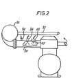
- Figure 2 schematically shows a water mist detector in accordance with the invention.
- Referring to Figure 1, the oil mist detector 2 comprises a box 4 which is sealed and has a dark-coloured interior to help prevent incoming or reflected light from affecting the operation of the detector. The oil mist detector 2 further comprises a
measuring compartment 10 which is connected to a conduit 6 which leads out of the box 4 and extends for a short distance before leading to the interior of a crankcase compartment 8. - The measuring
compartment 10 is also connected to anoutlet passage 12 leading to afan 14. Thefan 14 draws air from the crankcase compartment 8 through the conduit 6, the measuringcompartment 10 and theoutlet passage 12. - The
outlet passage 12 has several branch passages, one of which is indicated at 16, leading to other detectors (not shown) for detecting oil mist in other crankcase compartments of the engine being monitored. Thefan 14 is operable to draw air through each crankcase compartment being monitored. - The detector 2 also includes two infra-red light sources, a
main source 18 and atest source 20 which are arranged to direct light into the measuringcompartment 10 in generally mutually transverse, preferably perpendicular, directions. The detector 2 further includes alight sensor 22 positioned in line with thetest source 20 and connected to a printedcircuit board 24. - In use, any oil mist generated by overheating of the
oil 26 in the crankcase compartment 8 which may be caused by a fault in the engine is drawn by thefan 14 through the conduit 6 and into the measuringcompartment 10. - During normal operation, the
light source 18 is turned on and thetest source 20 is turned off. - If there is any oil mist in the
compartment 10, the light from thesource 18 will be scattered through various angles depending on the size of the mist particles and some light will be reflected towards thelight sensor 22. An amplifier on the printedcircuit board 24 receives the output of thelight sensor 22 and detects when the reflected light exceeds a predetermined level to provide a signal online 28 for generating an alarm and/or stopping the engine. - The conduit 6 extends upwardly and around a U-bend before reaching the
measuring compartment 10. This configuration avoids the collection of unwanted oil deposits which may otherwise collect in themeasuring compartment 10. Thecompartment 10 is effectively an enlargement of the conduit 6, the configuration of which allows thelight sources light sensor 22 to be positioned out of the main air flow path, which further reduces the risk of unwanted oil deposits on these elements, thus increasing the reliability of the device. - The detector 2 can be tested by turning on the
light source 20 and determining whether an alarm is given in response to thelight sensor 22 receiving light from this source. - In the preferred embodiment, the detector has a control circuit which regularly turns on the
source 20 to test the detector, and if thesensor 22 does not provide a signal indicating that light has been received, the control circuit gives an indication that the detector is not operating correctly. - The use of reflected light to indicate the presence of oil mist enhances the sensitivity of the detector. This means that the measuring
compartment 10 need not be very large, and in fact the entire detector 2 can be small and compact, thus saving manufacturing costs and facilitating fixture of the device in an engine. - If desired, the conduit 6 can terminate in an aperture in the wall of the box 4, and the box 4 can be secured directly to the wall of the crankcase compartment 8 with this aperture aligned with another aperture in the crankcase wall.
- Referring to Figure 2, the turbine of a turbo-
compressor 30 is driven by exhaust gases from an engine, which are received from apipe 32. The turbo-compressor 30 is automatically brought into service when desired, in a known manner. First, air alone is delivered to the fuel/air mixing point in the induction system of the engine, the turbine performance being governed by controlling the exhaust gas admitted to the turbine. Beyond a predetermined manifold pressure, typically 9 lbs. per square inch (.6 atm.), it is necessary to cool the system. For this purpose, a pressure-switch 34 is used to activate a water-injector 36, which sprays water droplets into theinduction manifold 38 to cool the system and ensure that the engine may be operated safely at higher pressures. - A mist or
spray detector 40 in accordance with the invention is situated downstream of the water-injector 36. Thedetector 40 comprises alight source 42 and a light sensor (not visible in the Figure) both of which are located in the manifold 38 and both of which face downwardly. Thedetector 40 is brought into service when the pressure-switch 34 activates theinjector 36. In the presence of a water mist or spray, there is a sufficient amount of light emitted fromlight source 42 reflected from the mist and travelling upwardly to illuminate the light sensor and provide an output signal. The inner surface of the manifold 38 may be blackened to reduce unwanted reflection therefrom. - If the
spray detector 40 fails to detect water after the pressure-switch 34 is operated, a warning device is triggered and/or the engine is automatically brought to a lower speed by adjusting the throttle or is switched off altogether.
Claims (10)
Priority Applications (1)
| Application Number | Priority Date | Filing Date | Title |
|---|---|---|---|
| AT82303811T ATE22596T1 (en) | 1981-07-21 | 1982-07-20 | DEVICE FOR ENGINE MONITORING. |
Applications Claiming Priority (2)
| Application Number | Priority Date | Filing Date | Title |
|---|---|---|---|
| GB8122360 | 1981-07-21 | ||
| GB8122360 | 1981-07-21 |
Publications (3)
| Publication Number | Publication Date |
|---|---|
| EP0071391A2 true EP0071391A2 (en) | 1983-02-09 |
| EP0071391A3 EP0071391A3 (en) | 1983-05-04 |
| EP0071391B1 EP0071391B1 (en) | 1986-10-01 |
Family
ID=10523373
Family Applications (1)
| Application Number | Title | Priority Date | Filing Date |
|---|---|---|---|
| EP82303811A Expired EP0071391B1 (en) | 1981-07-21 | 1982-07-20 | Apparatus for monitoring engines |
Country Status (5)
| Country | Link |
|---|---|
| US (1) | US4475382A (en) |
| EP (1) | EP0071391B1 (en) |
| JP (1) | JPS5826251A (en) |
| AT (1) | ATE22596T1 (en) |
| DE (1) | DE3273568D1 (en) |
Cited By (8)
| Publication number | Priority date | Publication date | Assignee | Title |
|---|---|---|---|---|
| GB2214307A (en) * | 1988-01-04 | 1989-08-31 | Pittway Corp | A unit with remote test initiation apparatus |
| US6137582A (en) * | 1996-09-13 | 2000-10-24 | Electrical Engineering Company Ltd. | Device for determining measured values, especially the concentration of an aerosol in a closed space of a working machine |
| RU2171902C2 (en) * | 1996-09-13 | 2001-08-10 | Электрикал Инджиниринг Компани, Лтд. | Device for checking concentration of aerosol in closed chamber of working machine |
| RU2291308C1 (en) * | 2005-04-28 | 2007-01-10 | Государственное Научное Учреждение "Институт Механики Металлополимерных Систем Им. В.А. Белого Нан Беларуси" | Device for checking concentration of foot particles in diesel oil |
| EP2386733A1 (en) | 2010-05-14 | 2011-11-16 | Schaller Automation Industrielle Automationstechnik GmbH & Co. KG | Assembly and method for determining the parameters of gases and/or an aerosol for a work machine |
| EP2615270A1 (en) | 2012-01-13 | 2013-07-17 | Schaller Automation Industrielle Automationstechnik GmbH & Co. KG | Device for removing and reclaiming crank chamber gases from a combustion engine |
| EP2615269A1 (en) | 2012-01-13 | 2013-07-17 | Schaller Automation Industrielle Automationstechnik GmbH & Co. KG | Device and method for determining the parameters of gases and/or an aerosol for a work machine |
| WO2022090511A1 (en) * | 2020-10-30 | 2022-05-05 | Heinzmann Gmbh & Co. Kg | Oil mist detector for detecting and/or analyzing oil-air mixtures, comprising an optical measuring assembly, and corresponding method |
Families Citing this family (12)
| Publication number | Priority date | Publication date | Assignee | Title |
|---|---|---|---|---|
| DE3434995C2 (en) * | 1984-09-24 | 1986-10-09 | Schaller-Automation Industrielle Automationstechnik KG, 6653 Blieskastel | Device for monitoring the lubrication of large diesel engines |
| JPS61111451A (en) * | 1984-11-05 | 1986-05-29 | Toyota Central Res & Dev Lab Inc | Oil mist detection device |
| JPS61111450A (en) * | 1984-11-05 | 1986-05-29 | Toyota Central Res & Dev Lab Inc | Oil mist detection device |
| JPS61126740U (en) * | 1985-01-29 | 1986-08-08 | ||
| US4750350A (en) * | 1987-02-17 | 1988-06-14 | Klein Lawrence W | Combustion leak tester |
| US5266516A (en) * | 1992-01-02 | 1993-11-30 | Chartered Semiconductor Manufacturing Pte Ltd | Method for making electrical contact through an opening of one micron or less for CMOS technology |
| GB9415944D0 (en) * | 1994-08-06 | 1994-09-28 | Leetech Maritime Uk Limited | Oil mist density monitor |
| GB2309076B (en) * | 1996-01-10 | 1999-08-11 | Kidde Fire Protection Ltd | Particle separation and detection apparatus |
| EP1923694B1 (en) * | 2006-11-20 | 2010-02-10 | MAHLE International GmbH | Method and device for measuring the amount of oil in a gas flow |
| CN102042945B (en) * | 2010-11-03 | 2012-02-01 | 北京航空航天大学 | A method for measuring the concentration of oil mist in a closed gearbox |
| US20120291535A1 (en) * | 2011-05-20 | 2012-11-22 | Caterpillar Inc. | Oil mist detector test rig |
| DE102017123495B3 (en) * | 2017-10-10 | 2019-04-11 | Man Diesel & Turbo Se | Internal combustion engine |
Family Cites Families (10)
| Publication number | Priority date | Publication date | Assignee | Title |
|---|---|---|---|---|
| US2907993A (en) * | 1956-12-21 | 1959-10-06 | Graviner Manufacturing Co | Detectors of oil mists and the like |
| US3202826A (en) * | 1961-09-01 | 1965-08-24 | Exxon Research Engineering Co | Haze meter |
| US3358148A (en) * | 1963-01-29 | 1967-12-12 | Exxon Research Engineering Co | Haze measuring apparatus with solid block with cavity |
| GB1129402A (en) * | 1966-02-24 | 1968-10-02 | Kidde Walter Co Ltd | Improvements in or relating to detectors for smoke and like particles |
| GB1200307A (en) * | 1966-11-28 | 1970-07-29 | Central Electr Generat Board | Improvements in or relating to the monitoring of gas-borne particles |
| JPS5526515B2 (en) * | 1974-03-04 | 1980-07-14 | ||
| JPS52112345A (en) * | 1976-03-18 | 1977-09-20 | Agency Of Ind Science & Technol | Oil mist detector |
| EP0017007A1 (en) * | 1979-03-31 | 1980-10-15 | Desitek Design und Vertrieb technischer Geräte GmbH | Measuring device for recording turbidity, especially of fluids |
| ATE4251T1 (en) * | 1979-07-13 | 1983-08-15 | Securiton Ag | METHOD FOR DETECTING AEROSOLS IN AIR LOCATED IN A TEST ZONE AND EQUIPMENT FOR CARRYING OUT THE SAME. |
| JPS5580532A (en) * | 1979-12-20 | 1980-06-17 | Teijin Ltd | Direct spun yarn drawing apparatus |
-
1982
- 1982-07-19 JP JP57127430A patent/JPS5826251A/en active Pending
- 1982-07-20 AT AT82303811T patent/ATE22596T1/en active
- 1982-07-20 EP EP82303811A patent/EP0071391B1/en not_active Expired
- 1982-07-20 DE DE8282303811T patent/DE3273568D1/en not_active Expired
- 1982-07-21 US US06/400,417 patent/US4475382A/en not_active Expired - Lifetime
Cited By (13)
| Publication number | Priority date | Publication date | Assignee | Title |
|---|---|---|---|---|
| GB2214307A (en) * | 1988-01-04 | 1989-08-31 | Pittway Corp | A unit with remote test initiation apparatus |
| GB2214307B (en) * | 1988-01-04 | 1992-08-26 | Pittway Corp | A unit with remote test initiation |
| US6137582A (en) * | 1996-09-13 | 2000-10-24 | Electrical Engineering Company Ltd. | Device for determining measured values, especially the concentration of an aerosol in a closed space of a working machine |
| RU2171902C2 (en) * | 1996-09-13 | 2001-08-10 | Электрикал Инджиниринг Компани, Лтд. | Device for checking concentration of aerosol in closed chamber of working machine |
| RU2291308C1 (en) * | 2005-04-28 | 2007-01-10 | Государственное Научное Учреждение "Институт Механики Металлополимерных Систем Им. В.А. Белого Нан Беларуси" | Device for checking concentration of foot particles in diesel oil |
| WO2011141191A1 (en) | 2010-05-14 | 2011-11-17 | Schaller Automation Industrielle Automationstechnik Gmbh & Co. Kg | System and method for determining readings of gases and/or an aerosol for a machine |
| EP2386733A1 (en) | 2010-05-14 | 2011-11-16 | Schaller Automation Industrielle Automationstechnik GmbH & Co. KG | Assembly and method for determining the parameters of gases and/or an aerosol for a work machine |
| US8695400B2 (en) | 2010-05-14 | 2014-04-15 | Uwe Gnauert | System and method for determining readings of gases and/or an aerosol for a machine |
| EP2615270A1 (en) | 2012-01-13 | 2013-07-17 | Schaller Automation Industrielle Automationstechnik GmbH & Co. KG | Device for removing and reclaiming crank chamber gases from a combustion engine |
| EP2615269A1 (en) | 2012-01-13 | 2013-07-17 | Schaller Automation Industrielle Automationstechnik GmbH & Co. KG | Device and method for determining the parameters of gases and/or an aerosol for a work machine |
| WO2013104454A1 (en) | 2012-01-13 | 2013-07-18 | Schaller-Automation | Device and method for ascertaining measured values of gases and/or an aerosol for a machine |
| US9080975B2 (en) | 2012-01-13 | 2015-07-14 | Schaller-Automation Industrielle Automationstechnik GmbH & Co. KG | Device and method for ascertaining measured values of gases and/or an aerosol for a machine |
| WO2022090511A1 (en) * | 2020-10-30 | 2022-05-05 | Heinzmann Gmbh & Co. Kg | Oil mist detector for detecting and/or analyzing oil-air mixtures, comprising an optical measuring assembly, and corresponding method |
Also Published As
| Publication number | Publication date |
|---|---|
| ATE22596T1 (en) | 1986-10-15 |
| DE3273568D1 (en) | 1986-11-06 |
| EP0071391B1 (en) | 1986-10-01 |
| US4475382A (en) | 1984-10-09 |
| JPS5826251A (en) | 1983-02-16 |
| EP0071391A3 (en) | 1983-05-04 |
Similar Documents
| Publication | Publication Date | Title |
|---|---|---|
| EP0071391A2 (en) | Apparatus for monitoring engines | |
| RU145685U1 (en) | VACUUM VEHICLE ENGINE SYSTEM | |
| US8146408B2 (en) | Method for testing gas turbine engines | |
| JPH11500532A (en) | Fuel vapor leak detector | |
| US5168747A (en) | System and method for locating leaks in steam turbine systems | |
| KR940005952B1 (en) | Lubrication device | |
| IT8447789A1 (en) | "Electronic control system for diesel engines". | |
| US4379227A (en) | Apparatus for and a method of monitoring the build-up of ice | |
| KR100355352B1 (en) | Device for testing pollution level of vehicle air filter | |
| US4393692A (en) | Static pressure probe and method | |
| US9080975B2 (en) | Device and method for ascertaining measured values of gases and/or an aerosol for a machine | |
| JPH09177530A (en) | Internal combustion engine | |
| CN215865820U (en) | Aeroengine test fault monitoring system | |
| EP3954877B1 (en) | System and method for detection of excessive flow in a fluid system | |
| CN110312903A (en) | Methane security system for transport refrigeration unit | |
| US11473532B2 (en) | General aviation carburetor testing with turbocharger and analysis device | |
| JP2001522994A (en) | Sample search system | |
| US4687327A (en) | Oil mist monitor | |
| US5277057A (en) | Gasoline detecting device | |
| US10094341B2 (en) | Air intake system of an internal combustion engine | |
| JPH06174580A (en) | Leakage detector for combustion gas of internal combustion engine | |
| US5465614A (en) | Apparatus and method for non-intrusive testing of a motor vehicle canister purge system | |
| JPS5458108A (en) | Method and device for checking airtight part of engine | |
| CN217380718U (en) | Cloud platform control system applied to standby generator set along highway | |
| KR200462522Y1 (en) | PCO non-flow monitoring for main engine |
Legal Events
| Date | Code | Title | Description |
|---|---|---|---|
| PUAI | Public reference made under article 153(3) epc to a published international application that has entered the european phase |
Free format text: ORIGINAL CODE: 0009012 |
|
| AK | Designated contracting states |
Designated state(s): AT BE CH DE FR GB IT LI LU NL SE |
|
| PUAL | Search report despatched |
Free format text: ORIGINAL CODE: 0009013 |
|
| AK | Designated contracting states |
Designated state(s): AT BE CH DE FR GB IT LI LU NL SE |
|
| 17P | Request for examination filed |
Effective date: 19831029 |
|
| RAP1 | Party data changed (applicant data changed or rights of an application transferred) |
Owner name: QUALITY MONITORING INSTRUMENTS LIMITED |
|
| GRAA | (expected) grant |
Free format text: ORIGINAL CODE: 0009210 |
|
| AK | Designated contracting states |
Kind code of ref document: B1 Designated state(s): AT BE CH DE FR GB IT LI LU NL SE |
|
| REF | Corresponds to: |
Ref document number: 22596 Country of ref document: AT Date of ref document: 19861015 Kind code of ref document: T |
|
| ITF | It: translation for a ep patent filed | ||
| REF | Corresponds to: |
Ref document number: 3273568 Country of ref document: DE Date of ref document: 19861106 |
|
| ET | Fr: translation filed | ||
| PLBE | No opposition filed within time limit |
Free format text: ORIGINAL CODE: 0009261 |
|
| STAA | Information on the status of an ep patent application or granted ep patent |
Free format text: STATUS: NO OPPOSITION FILED WITHIN TIME LIMIT |
|
| 26N | No opposition filed | ||
| ITTA | It: last paid annual fee | ||
| EPTA | Lu: last paid annual fee | ||
| EAL | Se: european patent in force in sweden |
Ref document number: 82303811.2 |
|
| PGFP | Annual fee paid to national office [announced via postgrant information from national office to epo] |
Ref country code: FR Payment date: 20010825 Year of fee payment: 20 |
|
| PGFP | Annual fee paid to national office [announced via postgrant information from national office to epo] |
Ref country code: DE Payment date: 20010828 Year of fee payment: 20 Ref country code: AT Payment date: 20010828 Year of fee payment: 20 |
|
| PGFP | Annual fee paid to national office [announced via postgrant information from national office to epo] |
Ref country code: SE Payment date: 20010829 Year of fee payment: 20 |
|
| PGFP | Annual fee paid to national office [announced via postgrant information from national office to epo] |
Ref country code: NL Payment date: 20010830 Year of fee payment: 20 Ref country code: GB Payment date: 20010830 Year of fee payment: 20 |
|
| PGFP | Annual fee paid to national office [announced via postgrant information from national office to epo] |
Ref country code: LU Payment date: 20010911 Year of fee payment: 20 |
|
| PGFP | Annual fee paid to national office [announced via postgrant information from national office to epo] |
Ref country code: BE Payment date: 20010918 Year of fee payment: 20 |
|
| PGFP | Annual fee paid to national office [announced via postgrant information from national office to epo] |
Ref country code: CH Payment date: 20010930 Year of fee payment: 20 |
|
| BE20 | Be: patent expired |
Free format text: 20020720 *QUALITY MONITORING INSTRUMENTS LTD |
|
| REG | Reference to a national code |
Ref country code: GB Ref legal event code: IF02 |
|
| PG25 | Lapsed in a contracting state [announced via postgrant information from national office to epo] |
Ref country code: LI Free format text: LAPSE BECAUSE OF EXPIRATION OF PROTECTION Effective date: 20020719 Ref country code: GB Free format text: LAPSE BECAUSE OF EXPIRATION OF PROTECTION Effective date: 20020719 Ref country code: CH Free format text: LAPSE BECAUSE OF EXPIRATION OF PROTECTION Effective date: 20020719 |
|
| PG25 | Lapsed in a contracting state [announced via postgrant information from national office to epo] |
Ref country code: NL Free format text: LAPSE BECAUSE OF EXPIRATION OF PROTECTION Effective date: 20020720 Ref country code: LU Free format text: LAPSE BECAUSE OF EXPIRATION OF PROTECTION Effective date: 20020720 Ref country code: AT Free format text: LAPSE BECAUSE OF EXPIRATION OF PROTECTION Effective date: 20020720 |
|
| PG25 | Lapsed in a contracting state [announced via postgrant information from national office to epo] |
Ref country code: SE Free format text: LAPSE BECAUSE OF NON-PAYMENT OF DUE FEES Effective date: 20020721 |
|
| REG | Reference to a national code |
Ref country code: GB Ref legal event code: PE20 Effective date: 20020719 |
|
| REG | Reference to a national code |
Ref country code: CH Ref legal event code: PL |
|
| EUG | Se: european patent has lapsed |
Ref document number: 82303811.2 |
|
| NLV7 | Nl: ceased due to reaching the maximum lifetime of a patent |
Effective date: 20020720 |