EP0071210A2 - Laminated article for use as fire and heat protector - Google Patents
Laminated article for use as fire and heat protector Download PDFInfo
- Publication number
- EP0071210A2 EP0071210A2 EP82106679A EP82106679A EP0071210A2 EP 0071210 A2 EP0071210 A2 EP 0071210A2 EP 82106679 A EP82106679 A EP 82106679A EP 82106679 A EP82106679 A EP 82106679A EP 0071210 A2 EP0071210 A2 EP 0071210A2
- Authority
- EP
- European Patent Office
- Prior art keywords
- laminated body
- body according
- fire
- particles
- fibers
- Prior art date
- Legal status (The legal status is an assumption and is not a legal conclusion. Google has not performed a legal analysis and makes no representation as to the accuracy of the status listed.)
- Granted
Links
Images
Classifications
-
- D—TEXTILES; PAPER
- D04—BRAIDING; LACE-MAKING; KNITTING; TRIMMINGS; NON-WOVEN FABRICS
- D04H—MAKING TEXTILE FABRICS, e.g. FROM FIBRES OR FILAMENTARY MATERIAL; FABRICS MADE BY SUCH PROCESSES OR APPARATUS, e.g. FELTS, NON-WOVEN FABRICS; COTTON-WOOL; WADDING ; NON-WOVEN FABRICS FROM STAPLE FIBRES, FILAMENTS OR YARNS, BONDED WITH AT LEAST ONE WEB-LIKE MATERIAL DURING THEIR CONSOLIDATION
- D04H1/00—Non-woven fabrics formed wholly or mainly of staple fibres or like relatively short fibres
- D04H1/40—Non-woven fabrics formed wholly or mainly of staple fibres or like relatively short fibres from fleeces or layers composed of fibres without existing or potential cohesive properties
- D04H1/44—Non-woven fabrics formed wholly or mainly of staple fibres or like relatively short fibres from fleeces or layers composed of fibres without existing or potential cohesive properties the fleeces or layers being consolidated by mechanical means, e.g. by rolling
- D04H1/46—Non-woven fabrics formed wholly or mainly of staple fibres or like relatively short fibres from fleeces or layers composed of fibres without existing or potential cohesive properties the fleeces or layers being consolidated by mechanical means, e.g. by rolling by needling or like operations to cause entanglement of fibres
-
- B—PERFORMING OPERATIONS; TRANSPORTING
- B32—LAYERED PRODUCTS
- B32B—LAYERED PRODUCTS, i.e. PRODUCTS BUILT-UP OF STRATA OF FLAT OR NON-FLAT, e.g. CELLULAR OR HONEYCOMB, FORM
- B32B15/00—Layered products comprising a layer of metal
- B32B15/04—Layered products comprising a layer of metal comprising metal as the main or only constituent of a layer, which is next to another layer of the same or of a different material
- B32B15/08—Layered products comprising a layer of metal comprising metal as the main or only constituent of a layer, which is next to another layer of the same or of a different material of synthetic resin
-
- B—PERFORMING OPERATIONS; TRANSPORTING
- B32—LAYERED PRODUCTS
- B32B—LAYERED PRODUCTS, i.e. PRODUCTS BUILT-UP OF STRATA OF FLAT OR NON-FLAT, e.g. CELLULAR OR HONEYCOMB, FORM
- B32B15/00—Layered products comprising a layer of metal
- B32B15/20—Layered products comprising a layer of metal comprising aluminium or copper
-
- B—PERFORMING OPERATIONS; TRANSPORTING
- B32—LAYERED PRODUCTS
- B32B—LAYERED PRODUCTS, i.e. PRODUCTS BUILT-UP OF STRATA OF FLAT OR NON-FLAT, e.g. CELLULAR OR HONEYCOMB, FORM
- B32B27/00—Layered products comprising a layer of synthetic resin
- B32B27/12—Layered products comprising a layer of synthetic resin next to a fibrous or filamentary layer
-
- B—PERFORMING OPERATIONS; TRANSPORTING
- B32—LAYERED PRODUCTS
- B32B—LAYERED PRODUCTS, i.e. PRODUCTS BUILT-UP OF STRATA OF FLAT OR NON-FLAT, e.g. CELLULAR OR HONEYCOMB, FORM
- B32B5/00—Layered products characterised by the non- homogeneity or physical structure, i.e. comprising a fibrous, filamentary, particulate or foam layer; Layered products characterised by having a layer differing constitutionally or physically in different parts
- B32B5/22—Layered products characterised by the non- homogeneity or physical structure, i.e. comprising a fibrous, filamentary, particulate or foam layer; Layered products characterised by having a layer differing constitutionally or physically in different parts characterised by the presence of two or more layers which are next to each other and are fibrous, filamentary, formed of particles or foamed
- B32B5/24—Layered products characterised by the non- homogeneity or physical structure, i.e. comprising a fibrous, filamentary, particulate or foam layer; Layered products characterised by having a layer differing constitutionally or physically in different parts characterised by the presence of two or more layers which are next to each other and are fibrous, filamentary, formed of particles or foamed one layer being a fibrous or filamentary layer
-
- B—PERFORMING OPERATIONS; TRANSPORTING
- B32—LAYERED PRODUCTS
- B32B—LAYERED PRODUCTS, i.e. PRODUCTS BUILT-UP OF STRATA OF FLAT OR NON-FLAT, e.g. CELLULAR OR HONEYCOMB, FORM
- B32B5/00—Layered products characterised by the non- homogeneity or physical structure, i.e. comprising a fibrous, filamentary, particulate or foam layer; Layered products characterised by having a layer differing constitutionally or physically in different parts
- B32B5/22—Layered products characterised by the non- homogeneity or physical structure, i.e. comprising a fibrous, filamentary, particulate or foam layer; Layered products characterised by having a layer differing constitutionally or physically in different parts characterised by the presence of two or more layers which are next to each other and are fibrous, filamentary, formed of particles or foamed
- B32B5/30—Layered products characterised by the non- homogeneity or physical structure, i.e. comprising a fibrous, filamentary, particulate or foam layer; Layered products characterised by having a layer differing constitutionally or physically in different parts characterised by the presence of two or more layers which are next to each other and are fibrous, filamentary, formed of particles or foamed one layer being formed of particles, e.g. chips, granules, powder
-
- D—TEXTILES; PAPER
- D04—BRAIDING; LACE-MAKING; KNITTING; TRIMMINGS; NON-WOVEN FABRICS
- D04H—MAKING TEXTILE FABRICS, e.g. FROM FIBRES OR FILAMENTARY MATERIAL; FABRICS MADE BY SUCH PROCESSES OR APPARATUS, e.g. FELTS, NON-WOVEN FABRICS; COTTON-WOOL; WADDING ; NON-WOVEN FABRICS FROM STAPLE FIBRES, FILAMENTS OR YARNS, BONDED WITH AT LEAST ONE WEB-LIKE MATERIAL DURING THEIR CONSOLIDATION
- D04H1/00—Non-woven fabrics formed wholly or mainly of staple fibres or like relatively short fibres
- D04H1/40—Non-woven fabrics formed wholly or mainly of staple fibres or like relatively short fibres from fleeces or layers composed of fibres without existing or potential cohesive properties
- D04H1/42—Non-woven fabrics formed wholly or mainly of staple fibres or like relatively short fibres from fleeces or layers composed of fibres without existing or potential cohesive properties characterised by the use of certain kinds of fibres insofar as this use has no preponderant influence on the consolidation of the fleece
- D04H1/4282—Addition polymers
- D04H1/4291—Olefin series
-
- D—TEXTILES; PAPER
- D04—BRAIDING; LACE-MAKING; KNITTING; TRIMMINGS; NON-WOVEN FABRICS
- D04H—MAKING TEXTILE FABRICS, e.g. FROM FIBRES OR FILAMENTARY MATERIAL; FABRICS MADE BY SUCH PROCESSES OR APPARATUS, e.g. FELTS, NON-WOVEN FABRICS; COTTON-WOOL; WADDING ; NON-WOVEN FABRICS FROM STAPLE FIBRES, FILAMENTS OR YARNS, BONDED WITH AT LEAST ONE WEB-LIKE MATERIAL DURING THEIR CONSOLIDATION
- D04H1/00—Non-woven fabrics formed wholly or mainly of staple fibres or like relatively short fibres
- D04H1/40—Non-woven fabrics formed wholly or mainly of staple fibres or like relatively short fibres from fleeces or layers composed of fibres without existing or potential cohesive properties
- D04H1/42—Non-woven fabrics formed wholly or mainly of staple fibres or like relatively short fibres from fleeces or layers composed of fibres without existing or potential cohesive properties characterised by the use of certain kinds of fibres insofar as this use has no preponderant influence on the consolidation of the fleece
- D04H1/4374—Non-woven fabrics formed wholly or mainly of staple fibres or like relatively short fibres from fleeces or layers composed of fibres without existing or potential cohesive properties characterised by the use of certain kinds of fibres insofar as this use has no preponderant influence on the consolidation of the fleece using different kinds of webs, e.g. by layering webs
-
- D—TEXTILES; PAPER
- D04—BRAIDING; LACE-MAKING; KNITTING; TRIMMINGS; NON-WOVEN FABRICS
- D04H—MAKING TEXTILE FABRICS, e.g. FROM FIBRES OR FILAMENTARY MATERIAL; FABRICS MADE BY SUCH PROCESSES OR APPARATUS, e.g. FELTS, NON-WOVEN FABRICS; COTTON-WOOL; WADDING ; NON-WOVEN FABRICS FROM STAPLE FIBRES, FILAMENTS OR YARNS, BONDED WITH AT LEAST ONE WEB-LIKE MATERIAL DURING THEIR CONSOLIDATION
- D04H13/00—Other non-woven fabrics
Definitions
- the invention is therefore based on the object of creating a generic laminate in which the fine-grained material is retained and which serves as fire and heat protection for objects, but especially for humans should be applicable.
- the inner layer of the granular particles such as sand or; Like., Fire retardant additives, such as a gas-releasing or oxygen-diluting or consuming materials, are added.
- the granular particles can therefore be used as diluents or mixtures. This has the advantage that, for example, extinguishing powder can be introduced as an additive, the needling of which between the cover layers alone is not only difficult but also impossible because of their high dust risk.
- the fire-retardant additives can be present, for example, as granules, pellets or powder. They can be mixed with the granular particles, for example diluted by the same or present bound to the granular particles.
Abstract
Description
Die Erfindung betrifft einen Schichtkörper als Brand- und Wärmeschutz mit zwei Deckschichten, von denen mindestens die eine Fasermaterial enthält und von denen mindestens die eine ungewebt vorliegt, die körniges Material einschliessen und miteinander verbunden sind.The invention relates to a laminate as fire and heat protection with two cover layers, at least one of which contains fiber material and at least one of which is non-woven, which enclose granular material and are connected to one another.
Schichtkörper der vorgenannten Art sind z.B. als Feuerlöschdecken bekannt (DE-OS 23 52 019) die aus einer Bahn aus feuerfesten Glasfasern bestehen, die mindestens an einer Seite mit einer durch Wärme zerstörbaren Polyäthylenfolie vernäht ist und zwischen den Bahnen mindestens einen mit Feuerlöschmaterial gefüllten Raum besitzt. Die durch das Nähen gebildeten Längsnähte ergeben schlauchartige Rinnen, in denen das Feuerlöschmaterial sich bewegen, z.B. zusammenfallen oder zusammenballen, kann. Bei Beschädigung der Polyäthylenfolie staubt das sehr feine Material heraus und ergibt darüber hinaus eine starke Belästigung der Umwelt, wenn eine solche Beschädigung z.B. beim Transport oder bei der Lagerung eintritt. Die bekannte Feuerlöschdecke ist z.B. auch nur als Brandschutz von Sachen und z.B. nicht zum Schutz für Menschen einsetzbar, weil nicht nur eine Verletzung des menschlichen Körpers durch aufgeschmolzene Kunststoffpartikel, sondern auch Vergiftungen wegen des austretenden Staubes oder von Dämpfen beim Aufschmelzen der Polyäthylenfolie auftreten können. Löst sich z.B. bei Beschädigung des Nähfadens die Nähnaht ab, so ist der Zusammenhalt des Feuerlöschmaterials in den schlauchartigen Rinnen nicht mehr gewährleistet. Beim Aufschmelzen der Polyäthylenfolie beim Einsatz bei Brand staubt das Feuerlöschmaterial auch nur an den aufgeschmolzenen Stellen wie aus einer Spritze heraus.Laminates of the aforementioned type are e.g. known as fire blankets (DE-OS 23 52 019) which consist of a web of refractory glass fibers which is sewn on at least one side with a heat-destructible polyethylene film and has at least one space filled with fire-fighting material between the webs. The longitudinal seams formed by the sewing result in tubular channels in which the fire extinguishing material moves, e.g. can collapse or clump together. If the polyethylene film is damaged, the very fine material will dust out and, moreover, result in a severe nuisance to the environment if such damage occurs e.g. occurs during transport or storage. The known fire blanket is e.g. also only as fire protection of things and e.g. cannot be used to protect people, because not only an injury to the human body due to melted plastic particles, but also poisoning due to the escaping dust or vapors can occur when the polyethylene film is melted. E.g. dissolves If the sewing thread is damaged, the seam is no longer guaranteed to hold the fire-fighting material together in the hose-like channels. When the polyethylene film is melted when used in the event of fire, the fire extinguishing material only dustes at the melted points as if from a syringe.
Der Erfindung liegt deshalb die Aufgabe zugrunde, einen gattungsgemässen Schichtkörper zu schaffen, bei dem das feinkörnige Material festgehalten und der als Brand- und Wärmeschutz für Gegenstände, insbesondere aber auch für den Menschen anwendbar sein soll.The invention is therefore based on the object of creating a generic laminate in which the fine-grained material is retained and which serves as fire and heat protection for objects, but especially for humans should be applicable.
Diese Aufgabe wird erfindungsgemäss durch den Gegenstand des Anspruches 1 gelöst. Durch die vernadelten Deckschichten wird die Partikelschicht in vorteilhafter Weise mit einer Vielzahl der Fasern oder Fäden durchsetzt, die sich durch die Partikelschicht hindurch erstrecken und die Partikel in ihrer Lage halten. Es ist damit eine Vielzahl von Unterteilungen, z.B. Kammern, für die Partikel geschaffen, die von den Deckschichten und den vernadelten, sich quer zu den Deckschichten erstreckenden Fasern oder Fäden begrenzt sind. Dadurch erhält der Schichtkörper nicht nur einen eigenen Zusammenhalt, sondern die Partikel sind allseitig gehalten. Bei Beschädigungen, z.B. der Fasern oder Fäden, bleibt die Vernadelung an den nichtbeschädigten Stellen bestehen, weil die vernadelten Fasern oder Fäden untereinander unverbunden sind. Dadurch wird auch gewährleistet, dass die Partikel z.B. nur an der beschädigten Stelle austreten können, weil die weiteren vernadelten Stellen wie ein Riegel wirken. Es kann damit auch eine z.B. gleichmässige Durchmischung der Partikel mit Fasermaterial und eine dichte Anordnung derselben mit einem herkömmlichen Verfahren ohne kostspielige Massnahmen erfolgen, wie es z.B. durch Vernähen von Deckschichten unerreichbar ist.According to the invention, this object is achieved by the subject matter of claim 1. A large number of the fibers or threads which extend through the particle layer and hold the particles in their position are advantageously penetrated through the needled cover layers. It is a multitude of subdivisions, e.g. Chambers for which particles are created which are delimited by the cover layers and the needled fibers or threads extending transversely to the cover layers. This not only gives the laminate its own cohesion, but the particles are held on all sides. In the event of damage, e.g. of the fibers or threads, the needling remains in the undamaged areas because the needled fibers or threads are not connected to one another. This also ensures that the particles e.g. can only emerge from the damaged area because the other needled areas act like a bolt. It can also be used e.g. uniform mixing of the particles with fiber material and a dense arrangement of the same with a conventional method without costly measures, such as e.g. is inaccessible by sewing cover layers.
Bei den körnigen Partikeln handelt es sich vorzugsweise um ein reaktionsträges Material, wie z.B. Sand, Ton, Kies od. dgl. Derartige körnige Partikel können daher spröde sein und/oder auch abrasive Eigenschaften haben und z.B. eine Härte aufweisen, die sie beim Vernadeln vor Zerstörung schützt. Die Partikel weisen daher von ihrer Materie her Eigenschaften auf, die eigentlich gegen ein Vernadeln sprechen.-Es hat sich jedoch in überraschender Weise gezeigt, dass die Deckschichten mit üblichen Vernadelungstechniken mittels Vernadelungsnadeln mit Widerhaken, z.B. üblichen Filznadeln, ohne wesentliche Beschädigung wie Abnutzung oder Zerstörung derselben durch die Lage der körnigen Partikel hindurch vernadelt werden können.The granular particles are preferably an inert material, such as sand, clay, gravel or the like. Such granular particles can therefore be brittle and / or have abrasive properties and, for example, have a hardness that they need when needling to be destroyed protects. The particles therefore have properties that actually speak against needling.-However, it has surprisingly been shown that the top layers with conventional needling techniques using needling needles with barbs, for example conventional felting needles, without significant damage such as wear or destruction the same can be needled through the location of the granular particles.
Dies ist zum Teil darauf zurückzuführen, dass die körnigen Partikel vor dem Vernadeln vorzugsweise gegeneinander verschiebbar vorliegen und beim Vernadeln von Nadeln ge troffene Partikel seitlich ausweichen können.This is partly due to the fact that the granular particles are preferably displaceable relative to one another prior to needling and that particles hit ge can be laterally evaded when needles are needled.
Die vollkommen eingeschlossenen Partikel sind nicht wahllos oder willkürlich zwischen den Fasern des Schichtkörpers verteilt, sondern werden z.B. von den vernadelten Fasern oder Fäden durchsetzt, sodass eine gleichmässige Mischung mit den körnigen Partikeln erreicht werden kann. Durch die Vernadelung sind in vorteilhafter Weise z.B. Haltefasern oder -fäden erzeugt, durch welche die Partikel gegen eine Verschiebung in Richtung der Ebene mindestens der einen Deckschicht festgelegt und somit ein Rieseln derselben im Schichtkörper verhindert wird. Damit kann eine geschlossene Raumform des Schichtkörpers erreicht werden, die für Brand- und Wärmeschutzzwecke vielfältig einsetzbar ist. In einfachster Form besteht die innere Schicht ausschliesslich aus Sand. Hierdurch kann der Schichtkörper in vorteilhafter Weise sowohl zum Schutz von Gegenständen als auch von Menschen oder Tieren verwendet werden, da der Sand bekanntlich ein hochschmelzendes Produkt darstellt. Man kann daher z.B. eine Branddecke herstellen, die über das gegen Brand zu schützende Objekt oder über den Menschen gelegt oder geworfen werden kann. Bei dem Schichtkörper nach der Erfindung liegt daher vorzugsweise eine Flächenwirkung vor, die nicht von einem Aufschmelzen von einer Deckschicht abhängig ist, sondern der ganze Schichtkörper wirkt für sich. Der Brand kann daher in vorteilhafter Weise bereits durch Ueberdecken erstickt werden, wobei die Wärme vom Sand aufgenommen wird.The completely enclosed particles are not randomly or arbitrarily distributed between the fibers of the laminate, but are e.g. interspersed with the needled fibers or threads, so that an even mixture with the granular particles can be achieved. Due to the needling, e.g. Holding fibers or threads are produced, by means of which the particles are fixed against a shift in the direction of the plane of at least one cover layer and thus prevent the latter from trickling into the laminate. In this way, a closed spatial shape of the laminate can be achieved, which can be used in a variety of ways for fire and heat protection purposes. In its simplest form, the inner layer consists exclusively of sand. As a result, the laminated body can advantageously be used both for protecting objects and also for people or animals, since the sand is known to be a high-melting product. One can therefore e.g. create a fire blanket that can be placed or thrown over the object to be protected against fire or over people. In the laminate according to the invention, therefore, there is preferably a surface effect which is not dependent on melting from a cover layer, but rather the entire laminate acts on its own. The fire can therefore advantageously be suffocated by covering it, the heat being absorbed by the sand.
In vorteilhafter Weise bestehen beide Deckschichten aus Fasermaterial, das z.B. durch den Brand nicht abschmilzt, sondern verkohlt oder verbrennt,z.B. aus Wolle oder behandelten Zellulosefasern. Ein Durchbrennen der Fasern zum zu schützenden Objekt wird aber durch die Sandschicht verhindert, da Sand ein schlechtes Wärmeleitungsvermögen hat und so als Isolator wirkt. Bei Sand handelt es sich auch um ein spezifisch schweres Material, das je nach Körnung in hoher Dichte vorliegen kann, sodass der erfindungsgemässe Schichtkörper z.B. in Form einer Brandschutzdecke oder eines Brandschutzkissens durch seine eigene Schwere auf dem zu schützenden oder zu löschenden Objekt verbleibt und auf diesem satt anliegen und sich gegebenenfalls an dieses auch anschmiegen kann.Advantageously, both cover layers consist of fiber material which, for example, does not melt as a result of the fire, but instead chars or burns, for example from wool or treated cellulose fibers. Burning through the fibers to the object to be protected is prevented by the sand layer, since sand has poor thermal conductivity and thus as an insulator works. Sand is also a specifically heavy material which, depending on the grain size, can be present in high density, so that the laminated body according to the invention, for example in the form of a fire protection blanket or a fire protection cushion, remains on the object to be protected or extinguished due to its own weight and on this can be snug and, if necessary, nestle against it.
Eine besonders gute Wärmeschutzwirkung kann auch dadurch erreicht werden, dass mindestens die dem Feuer zugewandte Seite des Schichtkörpers, z.B. der Matte, mit einer reflektierenden Folie, z.B. einer Aluminiumfolie oder einer mit Aluminium bedampften Kunststoff-Folie, belegt wird. Hierdurch kann die Wärmestrahlung zusätzlich reflektiert und weniger Wärme überhaupt in den Schichtkörper eindringen.A particularly good thermal insulation effect can also be achieved by at least the side of the laminate facing the fire, e.g. the mat, with a reflective film, e.g. an aluminum foil or a plastic foil coated with aluminum. As a result, the heat radiation can be additionally reflected and less heat can penetrate into the laminate at all.
Darüber hinaus können der inneren Schicht aus den körnigen Partikeln, wie Sand od; dgl., feuerhemmende Zusätze, wie z.B. ein Gas abgebende oder Sauerstoff verdünnende oder verbrauchende Materialien, zugegeben werden. Die körnigen Partikel können daher als Verdünnungs- oder Mischungsmittel verwendet werden. Dieses hat den Vorteil, dass z.B. Löschpulver als Zusatz eingebracht sein kann, dessen Vernadeln zwischen den Deckschichten alleine, wegen ihrer hohen Staubgefahr nicht nur schwierig, sondern unmöglich ist. Die feuerhemmenden Zusätze können z.B. als Granulate, Pellets oder auch Pulver vorliegen. Sie können mit den körnigen Partikeln gemischt, z.B. durch dieselben verdünnt sein oder an die körnigen Partikel gebunden vorliegen. Durch den Einsatz der körnigen Partikel, z.B. als Verdünnungs- oder Mischungsmittel können kleine, aber auch ausreichend wirksame Mengen der feuerhemmenden Zusätze in einer vorteilhaften Weise verteilt und im Schichtkörper festgehalten werden, wie es z.B. bisher nicht möglich gewesen ist. Die feuerhemmenden Zusätze können z.B. derart verteilt, z.B. verdünnt, in der Partikelschicht vorliegen und/oder Eigenschaften besitzen, dass dieselben erst bei einer bestimmten Temperatur der körnigen Partikel, insbesondere wenn diese Sand sind, wirksam werden, d.h. sich z.B. feuerhemmend zersetzen. Durch die Verteilung der feuerhemmenden Zusätze in der Partikelschicht, insbesondere Sandschicht, im erfindungsgemässen Schichtkörper kann auch gewährleistet werden, dass eine Entmischung zwischen den körnigen Partikeln und den feuerhemmenden Zusätzen verhindert wird. Es kann vielmehr eine Dosierung von sehr schwerem Sandmaterial und einem sehr leichten Material, wie z.B. den feuerhemmenden Zusätzen, dicht nebeneinander in den durch den Schichtkörper gebildeten Kammern erfolgen.In addition, the inner layer of the granular particles such as sand or; Like., Fire retardant additives, such as a gas-releasing or oxygen-diluting or consuming materials, are added. The granular particles can therefore be used as diluents or mixtures. This has the advantage that, for example, extinguishing powder can be introduced as an additive, the needling of which between the cover layers alone is not only difficult but also impossible because of their high dust risk. The fire-retardant additives can be present, for example, as granules, pellets or powder. They can be mixed with the granular particles, for example diluted by the same or present bound to the granular particles. Through the use of the granular particles, for example as a diluent or mixing agent, small but also sufficiently effective amounts of the fire-retardant additives can be distributed in an advantageous manner and retained in the laminate, as has not been possible previously, for example. The fire-retardant additives can, for example, be distributed, for example diluted, in the particle layer and / or have properties such that they only become effective at a certain temperature of the granular particles, especially if they are sand, become effective, ie decompose, for example, fire-retardant. The distribution of the fire-retardant additives in the particle layer, in particular sand layer, in the layered body according to the invention can also ensure that segregation between the granular particles and the fire-retardant additives is prevented. Rather, very heavy sand material and a very light material, such as the fire-retardant additives, can be metered closely together in the chambers formed by the laminate.
Die feuerhemmenden Zusätze können trockene Chemikalien, z.B. Natriumbikarbonat (NaHC03), Kaliumbikarbonat (KHC03), Natriumdihydrogenphosphat (NaH2P04) oder Ammoniumhydrogensulphat (NH4HS04) sein.The fire retardant additives can be dry chemicals, e.g. sodium bicarbonate (NaHC0 3 ), potassium bicarbonate (KHC0 3 ), sodium dihydrogen phosphate (NaH 2 P0 4 ) or ammonium hydrogen sulfate (NH 4 HS0 4 ).
In vielfältiger Weise kann der erfindungsgemässe Schichtkörper z.B. als Matte, Kissen, Platte, Umhüllung, Decke oder Schlauch vorliegen und er kann biegsam, z.B. aufrollbar oder aufwickelbar sein.In many ways, the laminate according to the invention can e.g. as a mat, pillow, plate, cover, blanket or hose and it can be flexible, e.g. can be rolled up or wound up.
Da die körnigen Partikel durch einzelne Haltefasern in dem Schichtkörper gehalten werden, kann dieser auch in verschiedene Zuschnitte aufgeteilt werden, die dann z.B. mittels Nähen, Kleben oder auch Vernadeln zu einer Schutzkleidung verarbeitet werden können. Eine solche Schutzkleidung kann beispielsweise ein Mantel oder ein Schutzanzug mit eingearbeitetem Kopfteil für Feuerwehrleute sein.Since the granular particles are held in the laminate by individual holding fibers, this can also be divided into different blanks, which are then e.g. can be processed into protective clothing by means of sewing, gluing or even needling. Such protective clothing can be, for example, a coat or a protective suit with an incorporated head part for firefighters.
Die eine Deckschicht kann aus einem faserfreien Material, z.B. aus einer Kunststoff-Folie bestehen. Man kann hierdurch oder durch zusätzliches Beschichten mindestens eine Deckschicht luftundurchlässig machen und dadurch die Brandschutzwirkung verstärken, weil dann durch den Schichtkörper hindurch keine Luft zum Brandherd hindurchtreten kann. Man kann aber auch den Schichtkörper mit einer Flüssigkeit tränken und eine gewünschte Verbindung der körnigen Partikel untereinander und mit den Haltefasern oder -fäden herbeiführen. Hierdurch wird zwar eine höhere Steifigkeit in der Partikelschicht erzeugt, die jedoch durch die Biegsamkeit der Deckschichten zum Teil aufgehoben wird, die dann eine höhere Biegeelastizität aufweisen können, als die Partikelschicht. Auf diese Weise kann der erfindungsgemässe Schichtkörper z.B. auch in Form einer Platte hergestellt werden, die ebenfalls aufrollbar sein kann. Von dieser Platte können auch Streifen abgeschnitten werden, ohne dass körniges Material bzw. die körnigen Partikel herausfallen können, da sie an den Haltefasern oder -fäden gehalten werden. Als Flüssigkeit können je nach Material der Partikelschicht z.B. Wasser, Wasser mit einem Bindemittel oder ein flüssiges Bindemittel vorliegen. Bei Verwendung von z.B. Wasserglas kann in besonders vorteilhafter Weise eine unbrennbare Abbindung der körnigen Partikel, die dann Sand sein können, erfolgen. Es können den körnigen Partikeln aber auch blähende Materialien zugesetzt werden, die sich durch Flüssigkeit aufblähen und die Hohlräume ausfüllen.One cover layer can consist of a fiber-free material, for example a plastic film. As a result, or by additional coating, at least one cover layer can be made air-impermeable and the fire protection effect thereby increased, because then no air can pass through the laminate to the source of the fire. But you can also soak the laminate with a liquid and a desired one Connect the granular particles with each other and with the holding fibers or threads. Although this results in a higher rigidity in the particle layer, this is partially offset by the flexibility of the cover layers, which can then have a higher bending elasticity than the particle layer. In this way, the laminated body according to the invention can also be produced, for example, in the form of a plate which can also be rolled up. From this plate also strips can be cut off without granular material can fall out or the granular particles as they old fibers at the H or held yarns. Depending on the material of the particle layer, the liquid can be, for example, water, water with a binder or a liquid binder. If, for example, water glass is used, the granular particles, which can then be sand, can be non-combustibly bonded in a particularly advantageous manner. However, bulky materials can also be added to the granular particles, which inflate through liquid and fill the cavities.
Vorzugsweise sind die Haltefasern oder -fäden Bestandteil mindestens der einen Deckschicht, sodass dieselbe aktiv vernadelt ist. Die andere Deckschicht kann dagegen nur passiv vernadelt sein. Mindestens die eine Deckschicht besitzt dann Fasern oder Fäden von genügender Länge, damit dieselben sich durch die Partikelschicht hindurch in die andere Deckschicht erstrecken und eine gewünschte Festigkeit durch die Vernadelung erreicht wird. Die Länge der Fasern oder Fäden kann auch z.B. von der gewünschten Dicke des Schichtkörpers abhängen und z.B. 40 - 150 mm betragen. Die Deckschichten sind vorzugsweise über die gesamte Fläche des Schichtkörpers miteinander vernadelt, sodass eine ausreichende Vernadelungsdichte erreicht werden kann, die z.B. 20 - 200 Einstiche/cm2 beträgt.The holding fibers or threads are preferably part of at least one cover layer, so that the latter is actively needled. The other cover layer, on the other hand, can only be passively needled. At least one cover layer then has fibers or threads of sufficient length so that they extend through the particle layer into the other cover layer and a desired strength is achieved through the needling. The length of the fibers or threads can also e.g. depend on the desired thickness of the laminate and e.g. 40 - 150 mm. The cover layers are preferably needled with one another over the entire surface of the laminated body, so that a sufficient needling density can be achieved, e.g. 20 - 200 punctures / cm2.
In einer weiteren Ausführungsform weist die eine Deckschicht mit den Partikeln ausgefüllte Vertiefungen auf, wobei diese Vertiefungen näpfchenartig oder auch länglich ausgebildet sein können. Hierdurch ist es möglich, z.B. einen besonders biegsamen, um die Stege zwischen den Näpfchen biegbaren Schichtkörper zu erhalten. Die Deckschichten können dabei an den vertiefungsfreien Stellen miteinander vernadelt und an den Vertiefungen selbst unvernadelt vorliegen, wodurch z.B. bei feuerhemmenden Zusätzen zu den körnigen Partikeln diese in besonders vorteilhafter Weise von Haltefasern frei wirken können.In a further embodiment, the one cover layer has depressions filled with the particles, wherein these Wells can be cup-shaped or elongated. This makes it possible, for example, to obtain a particularly flexible laminated body in order to obtain the webs which can be bent between the cells. The cover layers can be needled to each other at the recess-free locations and needled to the recesses themselves, so that, for example, fire-retardant additives to the granular particles can have a particularly advantageous effect of holding fibers free.
Die Deckschichten können natürliche oder synthetische Fasern oder-.Gemische derselben enthalten. Dies können Glasfasern, Steinwollfasern, Silikatfasern, aber auch Fasern aus Plastikmaterial, wie z.B. Polypropylen- oder PVC-Fasern, sein. PVC-Fasern können den Vorteil haben, dass sie z.B. unbrennbar sind und daher der Schichtkörper nach der Erfindung mit derartigen Fasern in vorteilhafter Weise zum Schutz von Menschen gegen Brand und Wärme eingesetzt werden kann. Mit einem erfindungsgemässen Schichtkörper z.B. in Form einer Matte oder Decke können auch Gegenstände, z.B. Schränke, Panzerschränke . od. dgl. umhüllt werden, wobei dies auch noch bei einem akuten Brand erfolgen kann, indem man den deckenartigen Schichtkörper um die zu schützenden Gegenstände hüllt und ihn zusätzlich auch mit Wasser besprengt bzw. anfeuchtet. Ein z.B. mit Wasser getränkter Schichtkörper kann dann einen zusätzlichen Brandschutz durch die Feuchtigkeit ergeben.The cover layers can contain natural or synthetic fibers or mixtures thereof. This can be glass fibers, rock wool fibers, silicate fibers, but also fibers made of plastic material, e.g. Polypropylene or PVC fibers. PVC fibers can have the advantage that they e.g. are non-flammable and therefore the laminated body according to the invention can be used with such fibers in an advantageous manner to protect people against fire and heat. With a laminate according to the invention e.g. objects in the form of a mat or blanket, e.g. Cupboards, armored cabinets. od. Like. Are wrapped, which can also be done in the event of an acute fire by wrapping the ceiling-like laminate around the objects to be protected and also sprinkled or moistened with water. A e.g. Laminate soaked with water can then provide additional fire protection through the moisture.
Eine einfache Ausbildung eines erfindungsgemässen Schichtkörpers, der z.B. in Form eines Mantels ausgebildet ist und dessen Deckschichten z.B. aus saugfähigen Fasern bestehen, kann z.B. als Schutzbekleidung in Hotels verwendet werden, wenn in diesen ein Brand ausbricht. Eine Person, die sich in einem brennenden Haus, wie z.B. einem Hotel, befindet, kann diese Bekleidung anziehen, sich mitsamt dieser Bekleidung unter eine Dusche stellen und, sobald diese Schutzbekleidung genug Wasser aufgesaugt hat, auch durch kleinere Brandbereiche hindurch aus dem Gebäude fliehen. Ist darüber hinaus, wie in vielen Hotels üblich, noch ein Löschschlauch vorhanden, so kann diese mit einer erfindungsgemässen Schutzbekleidung versehene Person von einer zweiten Person noch mit Wasser besprengt werden. Die in'dem Schichtkörper enthaltenen Sandpartikel sorgen dabei dafür, dass auch dann, wenn an der Aussenfläche der Bekleidung kein Wasser mehr vorhanden ist, die Wärme nicht so schnell durch die Bekleidung hindurchdringt.A simple design of a laminated body according to the invention, which is designed, for example, in the form of a jacket and whose cover layers consist, for example, of absorbent fibers, can be used, for example, as protective clothing in hotels if a fire breaks out in them. A person who is in a burning house, such as a hotel, can put on this clothing, put it together with this clothing under a shower and, as soon as this protective clothing has absorbed enough water, also through smaller fire areas flee out of the building. If, in addition, as is customary in many hotels, there is still an extinguishing hose, then a person provided with protective clothing according to the invention can be sprinkled with water by a second person. The sand particles contained in the laminate ensure that even if there is no more water on the outer surface of the clothing, the heat does not penetrate through the clothing so quickly.
Weitere Einzelheiten und Vorteile der Erfindung ergeben sich aus den Unteransprüchen und aus den im folgenden, anhand der Zeichnung beschriebenen Ausführungsbeispielen. In der Zeichnung sind Teilbereiche erfindungsgemässer Schichtkörper im Schnitt schematisch und vergrössert dargestellt.Further details and advantages of the invention emerge from the subclaims and from the exemplary embodiments described below with reference to the drawing. In the drawing, partial areas of laminated bodies according to the invention are shown schematically and enlarged in section.
Es zeigt:
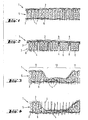
- Figur l eine erste Ausführungsform eines Schichtkörpers, bei dem beide Deckschichten aus einem Faservlies bestehen und die Partikel gleichmässig verteilt sind;
Figur 2 eine zweite Ausführungsform des Schichtkörpers, bei dem die eine Deckschicht mit näpfchenartigen Vertiefungen versehen ist, in der sich die Partikel befinden;Figur 3 eine dritte Ausführungsform, bei der die Partikel streifenförmig in dem Schichtkörper angeordnet sind, undFigur 4 eine vierte Ausführungsform, bei der der Schichtkörper gemäss Figur 3 von zwei Seiten her vernadelt ist.
- Figure 1 shows a first embodiment of a laminated body in which both cover layers consist of a nonwoven fabric and the particles are evenly distributed;
- Figure 2 shows a second embodiment of the laminated body, in which the one top layer is provided with cup-like depressions in which the particles are located;
- Figure 3 shows a third embodiment in which the particles are arranged in strips in the laminated body, and
- FIG. 4 shows a fourth embodiment in which the laminated body according to FIG. 3 is needled from two sides.
Ein Schichtkörper 1 weist eine hier obere Deckschicht 2 auf, die hier aktiv vernadelbar ist und aus einem Faservlies besteht. Eine hier untere Deckschicht 3, die mindestens passiv vernadelbar ist, wird von aus der oberen Deckschicht entnommenen Haltefasern 4 gegenüber der oberen Deckschicht 2 gehalten. Zwischen der oberen und der unteren Deckschicht 2 und 3 ist eine Schicht 5 aus körnigen Partikeln 6 angeordnet. Die beiden Deckschichten 2 und 3 sind durch die Partikelschicht 5 hindurch miteinander vernadelt. Die Vernadelung kann nach einem in der Nadelfilztechnologie bekannten Nadelverfahren erfolgen, wie es z.B. von R. Krcma im "Handbuch der Textilverbundstoffe", Deutscher Fachverlag, Frankfurt am Main, 1970, Seiten 198 - 202, beschrieben ist. In dieser Technologie werden zum Vernadeln am häufigsten Filznadeln mit dreieckigem Nadelschaft und seitlichen, gegen die Spitze zu gerichteten Widerhaken verwendet. Gebräuchlich sind auch andere Formen, wie Gabelnadeln und Loop-Nadeln. Auch die im Buch R. Krcma erwähnten Nähwirknadeln lassen sich für die Vernadelung des Schichtkörpers entsprechend verwenden. Die Filznadeln erfassen beim Einstechen in die Faserschicht 2 einzelne oder Büschel von Fasern 4 aus dieser Faserschicht und verflechten sie mit der unteren Deckschicht 3. Die Faserschicht 2 muss zu diesem Zweck aktiv nadelfähig sein, d.h., es sollen sich Fasern aus dieser Schicht erfassen lassen, wobei ein Teilstück dieser Fasern 4 noch in der Schicht 2 verankert bleibt.A laminated body 1 has an
Durch den Nadelvorgang werden nicht nur die beiden Schichten 2 und 3 miteinander verbunden, es werden auch die körnigen Partikel 6 der Schicht 5 durch die zahlreich auf die ganze Fläche des Schichtkörpers 1 verteilt durchgezogenen Haltefasern 4 am seitlichen Verschieben gehindert. Dadurch ist es möglich, den Schichtkörper in beliebige Formen zu zerschneiden, ohne dass die Gesteinspartikel in wesentlicher Menge aus der Schnittkante herausrieseln.The needling process not only connects the two
Die Schicht 5 von körnigen Partikeln 6 besteht hier aus Gesteinspartikeln von geringer Korngrösse, z.B. aus Sand, der definitionsgemäss eine Korngrösse von 0,02 - 2 mm aufweist. Aber auch Grobsand und sogar Kies und feinkörniger Splitt sind verwendbar, soweit sie das Durchstossen der Filznadeln nicht ganz verhindern. Vorteilhafte gemeinsame Merkmale dieser Materialien sind ihre relativ hohe Wärmekapazität, ihr relativ grosses Gewicht bezogen auf eine bestimmte Schichtdicke und ihr inertes Verhalten gegenüber anderen Stoffen.The
Wie sich schon aus der Zeichnung ergibt, kann die untere Deckschicht 3 aus verschiedenen Materialien bestehen. Diese untere Deckschicht 3 soll beim Durchstechen der Nadeln nicht aufsplittern und soll die durchgestochenen Haltefasern 4, z.B. elastisch, festhalten, z.B. durch Klemmung oder Verflechtung, d.h. die untere Deckschicht 3 soll passiv nadelfähig sein.As can be seen from the drawing, the
Es eignen sich hierfür z.B. Kunststoff-Folien aus weichelastischem Material (vgl. z.B. Fig. 2), Faserschichten in genügender Dichte, die durch den Nadelprozess selber noch weiter verdichtet und verfilzt werden, sodass sie die Gesteinspartikel zurückhalten, sowie adhäsiv gebundene Faserverbundstoffe. Die untere Deckschicht 3 kann auch aktiv nadelfähig sein, was erlaubt, den Schichtkörper l, wie in Figur 4 dargestellt, zusätzlich von der Gegenseite her zu vernadeln. Es ist auch möglich, auf eine Kunststoff-Folie oder dgl. als untere Schicht 3 eine weitere aktiv nadelfähige Faserschicht aufzulegen und den Schichtkörper 1 von beiden Seiten her zu vernadeln.For this, e.g. Plastic foils made of soft elastic material (see e.g. Fig. 2), fiber layers in sufficient density, which are further compressed and matted by the needle process itself, so that they retain the rock particles, as well as adhesive bonded fiber composites. The
Die Faserschicht, sei es als obere Deckschicht 2 oder als untere Deckschicht 3 eingesetzt, kann durch separate Vernadelung vorverdichtet sein, sie kann auf eine Trägerschicht, wie z.B. eine Kunststoff-Folie, einen Faserverbundstoff oder dgl., aufgenadelt sein, um die Handhabung bei der Herstellung zu erleichtern oder um das Durchsickern von feinen Gesteinspartikeln 6 und insbesondere von den gegebenenfalls, wie in Fig. 1 gezeigt, zugegebenen feuerhemmenden Stoffen zu verhindern.The fiber layer, whether used as an
Als Fasermaterial für das Faservlies kommen verschiedene organische oder anorganische Fasern in Frage. Es ist dabei nur darauf zu achten, dass diese Fasern nicht brennbar sind und einen besonders hohen Schmelzpunkt aufweisen. So lassen sich Metallkomplexfasern oder Fasern aromatischer Verbindungen ebenso verwenden wie PVC-Fasern. Es können auch saugfähige Fasern, wie Wolle, Baumwolle, Zellwolle oder Viskose, eingesetzt werden, die vorher zweckentsprechend behandelt werden.Various organic or inorganic fibers can be used as the fiber material for the nonwoven. It is only important to ensure that these fibers are not flammable and have a particularly high melting point. This is how metal complex fibers or fibers of aromatic compounds can be made use as well as PVC fibers. Absorbent fibers, such as wool, cotton, rayon or viscose, can also be used, which are treated appropriately beforehand.
Als Unterlagsschicht 3 kann anstelle des Faservlieses in Fig. 1 auch eine flache Folie, z.B. aus Aluminium oder aus mit Aluminium bedampftem Kunststoff oder auch ein Faserverbundstoff verwendet werden.Instead of the nonwoven fabric in Fig. 1, a flat film, e.g. made of aluminum or made of aluminum vapor-coated plastic or a fiber composite.
Wie insbesondere Figur 2 zeigt, kann diese Folie 7 mit Vertiefungen 8 versehen sein, die z.B. durch Tiefziehen im warmplastischen Zustand erzielt werden. Diese Vertiefungen 8 sind gemäss Figur 2 näpfchenartig ausgebildet. Diese Vertiefungen können jedoch auch länglich ausgebildet sein, wobei sie dann parallel zueinander zu liegen kommen und z.B. in ihrer Lage gegeneinander versetzt angeordnet sein können. Die Vertiefungen 8 öffnen sich dabei zur Deckschicht 2 hin, sodass in diese Vertiefungen die Partikel 6 eingebracht werden können. In dem Ausführungsbeispiel gemäss Figur 2 ist somit die Schicht 5 von Partikeln 6 nicht zusammenhängend, sondern in zahlreiche Portionen aufgeteilt. Die Nadeleinstiche können gleichmässig dicht über die ganze Fläche des Schichtkörpers 1 verteilt sein, wie dies bei den drei linken Näpfchen der Figur 2 gezeigt ist, wobei dort die Haltefasern 4 auch durch die Böden der Näpfchen hindurchgreifen. Wären die Haltefasern 4 weniger tief eingenadelt, wie dies einer nicht dargestellten Ausführungsform entspricht, so enden im Bereicht der Vertiefungen 8 diese Haltefasern in den Näpfchen selbst, während die Haltefasern die vertiefungsfreien Stellen 9 der Kunststoff-Folie 7 durchdringen, wodurch die Deckschicht 2 mit der als Kunststoff-Folie 7 ausgebildeten Unterlagsschicht verbunden wird. Dabei kann beim Vernadeln des Schichtkörpers so vorgegangen werden, dass die Nadelspitzen trotzdem den Boden der Vertiefungen 8 perforieren, sodass Fluide auch von Seiten der Unterlagsschicht 3 in die Vertiefungen 8 fliessen können. Gemäss der Darstellung in der rechten Hälfte der Figur 2 ist die Deckschicht 2 mit der Kunststoff-Folie 7 nur im Bereich der vertiefungsfreien Stellen 9 durch Haltefasern 4 verbunden. Wenngleich die näpfchenartig ausgebildeten Vertiefungen 8 selbst recht steif sind, so weist doch der Schichtkörper 1 eine relativ grosse Flexibilität auf, da die als Stege wirkenden, vertiefungsfreien Stellen 9 wie ein Scharnier wirken.As FIG. 2 shows in particular, this film 7 can be provided with
Bei der in Figuren 3 und 4 dargestellten Ausführungsform des Schichtkörpers 1 sind auf eine aktiv nadelfähige Faserschicht 3 Reihen oder Streifen von körnigen Partikeln 6 abgelegt. Diese bilden eine unterbrochene Zwischenschicht, durch welche hindurchgenadelt wird. Auf diese Reihen 11 von Partikeln 6 wird eine weitere aktiv nadelfähige Faserschicht 2 als Deckschicht abgelegt und der Schichtkörper von oben hindurch vernadelt.In the embodiment of the laminated body 1 shown in FIGS. 3 and 4, 3 rows or strips of
Die Ausführungsform gemäss Figur 4 entspricht im wesentlichen der Ausführungsform gemäss Figur 3, hier wird nun allerdings der Schichtkörper 1 auch von unten her vernadelt, d.h. die Haltefasern 4 sind sowohl aus der Deckschicht 2, als auch der Unterlagsschicht 4 entnommen.The embodiment according to FIG. 4 essentially corresponds to the embodiment according to FIG. 3, but here the laminated body 1 is also needled from below, i.e. the holding
Den Ausführungsformen gemäss Figuren 3 und 4 ist nun gemeinsam, dass sie an den partikelfreien Stellen 12 eine Art Scharnier bilden, weshalb auch der so ausgebildete Schichtkörper 1 trotz der relativ steifen, mit Partikeln 6 versehenen Reihen 11 insgesamt noch relativ flexibel bleibt. Dies ist insbesondere dann wichtig, wenn aus einem solchen Schichtkörper eine Feuerschutzbekleidung hergestellt werden soll.The embodiments according to FIGS. 3 and 4 now have in common that they form a type of hinge at the particle-
Aus folgender Tabelle, die nach Korndurchmesserbereichen der Partikel 6, zeilenweise gegliedert ist, ergeben sich bevorzugte zu verwendende Grössenbereiche für das Partikelgewicht pro Flächeneinheit, die Faserstärke, das Vliesgewicht je Faserschicht pro Flächeneinheit, die Nadelstärke und die Stichdichte.

Wird als Unterlagsschicht 3 eine Kunststoff-Folie 7 verwendet wie im Fall der Fig. 2, so beträgt die Foliendicke zwischen 30 und 200 µm, wobei bei grösserem Korndurchmesser auch eine dickere Folie verwendet werden sollte.If a plastic film 7 is used as the
Die Deckschicht 2 und die Unterlagsschicht 3 wurden identisch aus dem gleichen Material auf folgende Weise hergestellt. Auf eine Trägerfolie (in Fig. 1 nicht dargestellt) aus Polyäthylen von 0.1 mm Dicke wurde ein Fasergemisch von 200 g/m2 von Polyester-Fasern mit einem Fasertiter von 3.3 und 17 dtex und einer Stapellänge von 90 mm abgelegt. Die Fasern wurden mit der Folie mittels konventioneller Filznadeln mit 45 Stichen pro cm2 vorvernadelt. Eine solche vorvernadelte Faserschicht wurde mit den Faserbärten nach oben gerichtet auf den Zuführtisch der Nadelmaschine gelegt, dann darauf eine Schicht von gewaschenem Quarzsand der Korngrösse 0.5 - 0.75 mm in einer Menge von 7 kg/m2 gestreut. Die Schicht wurde sodann mit einer identischen vorvernadelten Faserschicht mit den Faserbärten nach unten gerichtet, zugedeckt. Der ganze Schichtkörper wurde mit konventionellen 25 - gauge Filznadeln und mit 30 Stichen pro cm vernadelt. Es entstand ein Schichtkörper von zirka 7.4 kg pro m2 Flächengewicht.The
Beispiel für die Herstellung eines Schichtkörpers 1, gemäss Fig. 2:
Als Unterlagsschicht 3 wurde eine Noppenfolie 7 aus Polyäthylen mit zylinderischen Vertiefungen (Noppen) von 1 cm Durchmesser und 5 mm Tiefe, 7'700 Noppen pro m 2 verwendet. Die Noppen wurden mit Quarzsand gestrichen gefüllt, dann mit einer Schicht von Polypropylen-Fasern 17 dtex, Stappellänge 90 mm, 200 g/m2 zugedeckt. Der Schichtkörper wurde mit konventionellen 25 - gauge Filznadeln mit 30 Stichen pro cm2 vernadelt. Es entstand ein Schichtkörper 1 von zirka 1.8 kgpro m 2 Flächengewicht. Die Noppen waren durch die Nadeleinstiche perforiert worden. Der Sand konnte jedoch nicht herausfallen.
- A pimple film 7 made of polyethylene with cylindrical depressions (pimples) of 1 cm in diameter and 5 mm in depth, 7'700 pimples per
m 2 was used as thebase layer 3. The knobs were filled with quartz sand, then covered with a layer of polypropylene fibers 17 dtex, staple length 90 mm, 200 g / m 2 . The laminate was needled with conventional 25-gauge felting needles with 30 stitches per cm 2 . A laminated body 1 of approximately 1.8 kg perm 2 basis weight was produced. The knobs had been perforated by the needle punctures. However, the sand could not fall out.
Mit einem erfindungsgemässen, als Löschmatte ausgebildeten Schichtkörper wurde ein Brandtest durchgeführt. Dazu wurden rund 500 g ofengetrocknete Kiefernholzspähne mit 1 Liter Dieselöl-Benzingemisch gezündet. Nachdem sich der Brand entfaltet hatte, wurde eine erfindungsgemässe erste Löschmatte auf die Brandstelle gelegt und diese damit zur Hälfte abgedeckt. Während unter dieser Löschmatte das Feuer sehr schnell erstickt werden konnte, wurde diese erste Löschmatte einer Kantenbeflammung ausgesetzt. Nach einiger Zeit wurde über die zweite Hälfte der Brandstelle eine zweite Löschmatte geworfen, wodurch der Brand insgesamt kurz darauf erlosch. Beide benutzten Löschmatten zeigten lediglich Sengstellen und keinerlei Branddurchbrüche. Die Beschädigungen der Löschmatte waren dabei so gering, dass eine Wiederverwendung der Löschmatten möglich gewesen wäre.A fire test was carried out with a laminated body according to the invention, which is designed as an extinguishing mat. For this purpose, around 500 g of oven-dried pine wood shavings were ignited with 1 liter of diesel oil and gasoline mixture. After the fire had started, a first extinguishing mat according to the invention was placed on the fire site and half of it was covered. While the fire could be suffocated very quickly under this extinguishing mat, this first extinguishing mat was exposed to edge flaming. After a while, a second extinguishing mat was thrown over the second half of the fire, causing the fire to go out shortly afterwards. Both extinguishing mats used only showed scorching spots and no fire breakthroughs. The damage to the extinguishing mat was so slight that it would have been possible to reuse the extinguishing mat.
Claims (23)
Priority Applications (1)
| Application Number | Priority Date | Filing Date | Title |
|---|---|---|---|
| AT82106679T ATE19269T1 (en) | 1981-07-27 | 1982-07-23 | LAYERED BODY FOR FIRE AND HEAT PROTECTION. |
Applications Claiming Priority (2)
| Application Number | Priority Date | Filing Date | Title |
|---|---|---|---|
| DE3129557 | 1981-07-27 | ||
| DE3129557 | 1981-07-27 |
Publications (3)
| Publication Number | Publication Date |
|---|---|
| EP0071210A2 true EP0071210A2 (en) | 1983-02-09 |
| EP0071210A3 EP0071210A3 (en) | 1984-05-09 |
| EP0071210B1 EP0071210B1 (en) | 1986-04-16 |
Family
ID=6137819
Family Applications (1)
| Application Number | Title | Priority Date | Filing Date |
|---|---|---|---|
| EP82106679A Expired EP0071210B1 (en) | 1981-07-27 | 1982-07-23 | Laminated article for use as fire and heat protector |
Country Status (5)
| Country | Link |
|---|---|
| EP (1) | EP0071210B1 (en) |
| JP (1) | JPS5824441A (en) |
| AT (1) | ATE19269T1 (en) |
| CA (1) | CA1229475A (en) |
| DE (1) | DE3270611D1 (en) |
Cited By (7)
| Publication number | Priority date | Publication date | Assignee | Title |
|---|---|---|---|---|
| FR2623823A1 (en) * | 1987-12-01 | 1989-06-02 | Dollfus Noack Sa | Thermal insulating felt and process for its manufacture |
| US5654064A (en) * | 1990-12-11 | 1997-08-05 | Claymax Corporation | Clay liner for steep slopes |
| DE19825645A1 (en) * | 1998-06-09 | 1999-12-16 | Paul Schreck | Sealing mat used to hold back water in underground engineering |
| DE19901344A1 (en) * | 1999-01-15 | 2000-07-20 | Paul Schreck | Sealing mat for below-ground construction and civil engineering has outer woven or nonwoven layers with an intermediate bonded tangled mass containing lodged swelling materials to give the required sealing and strength at a low cost |
| WO2012001504A3 (en) * | 2010-07-01 | 2012-03-01 | Promix S.R.L. | Thermo-acoustic blanket |
| CN111184965A (en) * | 2019-12-23 | 2020-05-22 | 中纺院(浙江)技术研究院有限公司 | Fire blanket capable of releasing incombustible gas |
| CN113059815A (en) * | 2021-03-23 | 2021-07-02 | 南通大学 | Preparation method of novel flame-retardant, heat-insulating and sound-absorbing composite material |
Families Citing this family (3)
| Publication number | Priority date | Publication date | Assignee | Title |
|---|---|---|---|---|
| JPS61115563U (en) * | 1984-12-29 | 1986-07-21 | ||
| DE10020859A1 (en) * | 2000-04-28 | 2001-10-31 | Nabento Vliesstoff Gmbh | Drainage mat and method and device for its production |
| GB2461060B (en) * | 2008-06-18 | 2010-06-23 | Sewoon T & S Co Ltd | Fiberglass pipe-shaped insulator and method of manufacturing the same |
Citations (11)
| Publication number | Priority date | Publication date | Assignee | Title |
|---|---|---|---|---|
| US2340370A (en) * | 1942-02-02 | 1944-02-01 | Robert A Doyle | Fire extinguishing blanket |
| DE1435762A1 (en) * | 1963-07-26 | 1968-12-19 | Brevetex S A | Multi-layered, needled surface structure with at least one insulation layer |
| DE1560651A1 (en) * | 1963-08-20 | 1969-09-11 | Brevetex S A | Damming surface structure |
| FR2022947A1 (en) * | 1968-11-09 | 1970-08-07 | Haussling Heinrich | Air filter mat |
| NL7212202A (en) * | 1972-09-07 | 1974-03-11 | ||
| DE2321362A1 (en) * | 1973-04-27 | 1974-11-07 | Naue Kg E A H | Water permeable mat - prevents erosion of river banks, has bulky fibrous batt secured to rot resistant base |
| DE2352019A1 (en) * | 1973-10-17 | 1975-04-30 | Davis Verna Grace Schmidtgeb | Blanket fire extinguisher -having extinguishing material - between fire resistant and heat rupturable sheets |
| US4064317A (en) * | 1975-02-05 | 1977-12-20 | Sumitomo Chemical Company, Limited | Flame-resistant plaster board and its manufacture |
| DE2716706A1 (en) * | 1977-04-15 | 1978-10-19 | Geb Boehmer Herta Erika Lohrum | Heat-reflective protective fabric - has hollow zones on under surface filled with incombustible or low burning material |
| DE2855059A1 (en) * | 1977-12-24 | 1979-07-05 | Breveteam Sa | FLAT, FLEXIBLE LAMINATED BODY FOR THE TREATMENT OF GASES OR LIQUIDS, THE PROCESS FOR ITS MANUFACTURING AND ITS USE |
| US4250172A (en) * | 1979-02-09 | 1981-02-10 | Hausheer Hans P | Needled fiber mat containing granular agent |
-
1982
- 1982-07-23 DE DE8282106679T patent/DE3270611D1/en not_active Expired
- 1982-07-23 AT AT82106679T patent/ATE19269T1/en not_active IP Right Cessation
- 1982-07-23 EP EP82106679A patent/EP0071210B1/en not_active Expired
- 1982-07-26 CA CA000408045A patent/CA1229475A/en not_active Expired
- 1982-07-27 JP JP57129706A patent/JPS5824441A/en active Pending
Patent Citations (11)
| Publication number | Priority date | Publication date | Assignee | Title |
|---|---|---|---|---|
| US2340370A (en) * | 1942-02-02 | 1944-02-01 | Robert A Doyle | Fire extinguishing blanket |
| DE1435762A1 (en) * | 1963-07-26 | 1968-12-19 | Brevetex S A | Multi-layered, needled surface structure with at least one insulation layer |
| DE1560651A1 (en) * | 1963-08-20 | 1969-09-11 | Brevetex S A | Damming surface structure |
| FR2022947A1 (en) * | 1968-11-09 | 1970-08-07 | Haussling Heinrich | Air filter mat |
| NL7212202A (en) * | 1972-09-07 | 1974-03-11 | ||
| DE2321362A1 (en) * | 1973-04-27 | 1974-11-07 | Naue Kg E A H | Water permeable mat - prevents erosion of river banks, has bulky fibrous batt secured to rot resistant base |
| DE2352019A1 (en) * | 1973-10-17 | 1975-04-30 | Davis Verna Grace Schmidtgeb | Blanket fire extinguisher -having extinguishing material - between fire resistant and heat rupturable sheets |
| US4064317A (en) * | 1975-02-05 | 1977-12-20 | Sumitomo Chemical Company, Limited | Flame-resistant plaster board and its manufacture |
| DE2716706A1 (en) * | 1977-04-15 | 1978-10-19 | Geb Boehmer Herta Erika Lohrum | Heat-reflective protective fabric - has hollow zones on under surface filled with incombustible or low burning material |
| DE2855059A1 (en) * | 1977-12-24 | 1979-07-05 | Breveteam Sa | FLAT, FLEXIBLE LAMINATED BODY FOR THE TREATMENT OF GASES OR LIQUIDS, THE PROCESS FOR ITS MANUFACTURING AND ITS USE |
| US4250172A (en) * | 1979-02-09 | 1981-02-10 | Hausheer Hans P | Needled fiber mat containing granular agent |
Cited By (7)
| Publication number | Priority date | Publication date | Assignee | Title |
|---|---|---|---|---|
| FR2623823A1 (en) * | 1987-12-01 | 1989-06-02 | Dollfus Noack Sa | Thermal insulating felt and process for its manufacture |
| US5654064A (en) * | 1990-12-11 | 1997-08-05 | Claymax Corporation | Clay liner for steep slopes |
| DE19825645A1 (en) * | 1998-06-09 | 1999-12-16 | Paul Schreck | Sealing mat used to hold back water in underground engineering |
| DE19901344A1 (en) * | 1999-01-15 | 2000-07-20 | Paul Schreck | Sealing mat for below-ground construction and civil engineering has outer woven or nonwoven layers with an intermediate bonded tangled mass containing lodged swelling materials to give the required sealing and strength at a low cost |
| WO2012001504A3 (en) * | 2010-07-01 | 2012-03-01 | Promix S.R.L. | Thermo-acoustic blanket |
| CN111184965A (en) * | 2019-12-23 | 2020-05-22 | 中纺院(浙江)技术研究院有限公司 | Fire blanket capable of releasing incombustible gas |
| CN113059815A (en) * | 2021-03-23 | 2021-07-02 | 南通大学 | Preparation method of novel flame-retardant, heat-insulating and sound-absorbing composite material |
Also Published As
| Publication number | Publication date |
|---|---|
| EP0071210B1 (en) | 1986-04-16 |
| DE3270611D1 (en) | 1986-05-22 |
| EP0071210A3 (en) | 1984-05-09 |
| ATE19269T1 (en) | 1986-05-15 |
| JPS5824441A (en) | 1983-02-14 |
| CA1229475A (en) | 1987-11-24 |
Similar Documents
| Publication | Publication Date | Title |
|---|---|---|
| EP0071212B1 (en) | Mat-like laminated article and method of producing the same | |
| DE2855059C2 (en) | Flat and flexible laminated body for treating gases or liquids | |
| EP0071213B1 (en) | Laminated article for construction purposes, and its application | |
| DE4018727C2 (en) | Flame barrier made of nonwoven | |
| EP0131759B1 (en) | Bags for insecticides | |
| DE3200959C2 (en) | ||
| DE4344805C2 (en) | Filter structure consisting of particles | |
| DE2434663A1 (en) | COMPOSITE POT CLEANER OR THE LIKE. AND PROCESS FOR ITS MANUFACTURING | |
| EP0071210B1 (en) | Laminated article for use as fire and heat protector | |
| EP3133196B1 (en) | Volume nonwoven fabric | |
| WO1986007011A1 (en) | Multilayer insulating body, method for its fabrication and utilization | |
| EP0752458B1 (en) | Process for flame-proofing treatment of textile sheet materials and products treated by such process | |
| EP0071211B1 (en) | Flexible, flat, sand containing laminated article for external use in body treatment | |
| DE102005032769A1 (en) | Hygiene products | |
| EP0661153B1 (en) | Lining material resistant to plant roots for attachment to a substrate | |
| DE4119989C2 (en) | Radiation protection mat for the shielding of radioactive radiation | |
| EP3758560B1 (en) | Covering, in particular quilt | |
| EP0073919A2 (en) | Use of a laminated flat article as textile material | |
| WO1998029012A1 (en) | Cell for filling coverlets or the like | |
| DE2842310A1 (en) | SHAFTSCASE VENTILATION CURTAIN FOR UNDERGROUND MINES AND METHOD FOR VENTILATING THEM | |
| DE202018004272U1 (en) | Nonwoven fabric structure with several layers | |
| DE1885517U (en) | UNWOVEN LAMINATE. | |
| AT403766B (en) | Screening mat | |
| DE1917850C3 (en) | Leather substitute | |
| DE10020859A1 (en) | Drainage mat and method and device for its production |
Legal Events
| Date | Code | Title | Description |
|---|---|---|---|
| PUAI | Public reference made under article 153(3) epc to a published international application that has entered the european phase |
Free format text: ORIGINAL CODE: 0009012 |
|
| AK | Designated contracting states |
Designated state(s): AT BE CH DE FR GB IT LI LU NL SE |
|
| RAP1 | Party data changed (applicant data changed or rights of an application transferred) |
Owner name: TESCH, GUENTER HORST |
|
| PUAL | Search report despatched |
Free format text: ORIGINAL CODE: 0009013 |
|
| AK | Designated contracting states |
Designated state(s): AT BE CH DE FR GB IT LI LU NL SE |
|
| 17P | Request for examination filed |
Effective date: 19840510 |
|
| GRAA | (expected) grant |
Free format text: ORIGINAL CODE: 0009210 |
|
| AK | Designated contracting states |
Kind code of ref document: B1 Designated state(s): AT BE CH DE FR GB IT LI LU NL SE |
|
| PG25 | Lapsed in a contracting state [announced via postgrant information from national office to epo] |
Ref country code: NL Effective date: 19860416 Ref country code: IT Free format text: LAPSE BECAUSE OF FAILURE TO SUBMIT A TRANSLATION OF THE DESCRIPTION OR TO PAY THE FEE WITHIN THE PRESCRIBED TIME-LIMIT;WARNING: LAPSES OF ITALIAN PATENTS WITH EFFECTIVE DATE BEFORE 2007 MAY HAVE OCCURRED AT ANY TIME BEFORE 2007. THE CORRECT EFFECTIVE DATE MAY BE DIFFERENT FROM THE ONE RECORDED. Effective date: 19860416 Ref country code: FR Free format text: THE PATENT HAS BEEN ANNULLED BY A DECISION OF A NATIONAL AUTHORITY Effective date: 19860416 Ref country code: BE Effective date: 19860416 |
|
| REF | Corresponds to: |
Ref document number: 19269 Country of ref document: AT Date of ref document: 19860515 Kind code of ref document: T |
|
| PG25 | Lapsed in a contracting state [announced via postgrant information from national office to epo] |
Ref country code: SE Effective date: 19860430 |
|
| REF | Corresponds to: |
Ref document number: 3270611 Country of ref document: DE Date of ref document: 19860522 |
|
| REG | Reference to a national code |
Ref country code: GB Ref legal event code: 746 |
|
| PG25 | Lapsed in a contracting state [announced via postgrant information from national office to epo] |
Ref country code: LU Free format text: LAPSE BECAUSE OF NON-PAYMENT OF DUE FEES Effective date: 19860731 |
|
| EN | Fr: translation not filed | ||
| NLV1 | Nl: lapsed or annulled due to failure to fulfill the requirements of art. 29p and 29m of the patents act | ||
| PLBE | No opposition filed within time limit |
Free format text: ORIGINAL CODE: 0009261 |
|
| STAA | Information on the status of an ep patent application or granted ep patent |
Free format text: STATUS: NO OPPOSITION FILED WITHIN TIME LIMIT |
|
| 26N | No opposition filed | ||
| PGFP | Annual fee paid to national office [announced via postgrant information from national office to epo] |
Ref country code: AT Payment date: 19920625 Year of fee payment: 11 |
|
| PG25 | Lapsed in a contracting state [announced via postgrant information from national office to epo] |
Ref country code: AT Effective date: 19930723 |
|
| PGFP | Annual fee paid to national office [announced via postgrant information from national office to epo] |
Ref country code: GB Payment date: 19940628 Year of fee payment: 13 |
|
| PGFP | Annual fee paid to national office [announced via postgrant information from national office to epo] |
Ref country code: DE Payment date: 19950706 Year of fee payment: 14 |
|
| PG25 | Lapsed in a contracting state [announced via postgrant information from national office to epo] |
Ref country code: GB Effective date: 19950723 |
|
| GBPC | Gb: european patent ceased through non-payment of renewal fee |
Effective date: 19950723 |
|
| PGFP | Annual fee paid to national office [announced via postgrant information from national office to epo] |
Ref country code: CH Payment date: 19960911 Year of fee payment: 15 |
|
| PG25 | Lapsed in a contracting state [announced via postgrant information from national office to epo] |
Ref country code: DE Effective date: 19970402 |
|
| PG25 | Lapsed in a contracting state [announced via postgrant information from national office to epo] |
Ref country code: LI Free format text: LAPSE BECAUSE OF NON-PAYMENT OF DUE FEES Effective date: 19970731 Ref country code: CH Free format text: LAPSE BECAUSE OF NON-PAYMENT OF DUE FEES Effective date: 19970731 |
|
| REG | Reference to a national code |
Ref country code: CH Ref legal event code: PL |