EP0070969B1 - Timepiece case/backcover assembly - Google Patents
Timepiece case/backcover assembly Download PDFInfo
- Publication number
- EP0070969B1 EP0070969B1 EP82103346A EP82103346A EP0070969B1 EP 0070969 B1 EP0070969 B1 EP 0070969B1 EP 82103346 A EP82103346 A EP 82103346A EP 82103346 A EP82103346 A EP 82103346A EP 0070969 B1 EP0070969 B1 EP 0070969B1
- Authority
- EP
- European Patent Office
- Prior art keywords
- surface portions
- case
- back cover
- cover member
- circular arc
- Prior art date
- Legal status (The legal status is an assumption and is not a legal conclusion. Google has not performed a legal analysis and makes no representation as to the accuracy of the status listed.)
- Expired
Links
- 238000010276 construction Methods 0.000 claims description 15
- 238000007789 sealing Methods 0.000 description 13
- 238000003754 machining Methods 0.000 description 7
- 230000002093 peripheral effect Effects 0.000 description 4
- 239000004033 plastic Substances 0.000 description 4
- 239000002184 metal Substances 0.000 description 3
- 239000002131 composite material Substances 0.000 description 2
- 238000004512 die casting Methods 0.000 description 2
- 238000004519 manufacturing process Methods 0.000 description 2
- 238000000034 method Methods 0.000 description 2
- XLYOFNOQVPJJNP-UHFFFAOYSA-N water Substances O XLYOFNOQVPJJNP-UHFFFAOYSA-N 0.000 description 2
- 229920001971 elastomer Polymers 0.000 description 1
- 239000000806 elastomer Substances 0.000 description 1
- 238000002347 injection Methods 0.000 description 1
- 239000007924 injection Substances 0.000 description 1
- 238000001746 injection moulding Methods 0.000 description 1
- 239000000463 material Substances 0.000 description 1
- 230000004048 modification Effects 0.000 description 1
- 238000012986 modification Methods 0.000 description 1
- 229920003052 natural elastomer Polymers 0.000 description 1
- 229920001194 natural rubber Polymers 0.000 description 1
- 230000035515 penetration Effects 0.000 description 1
- 229920003051 synthetic elastomer Polymers 0.000 description 1
- 239000005061 synthetic rubber Substances 0.000 description 1
Images



Classifications
-
- G—PHYSICS
- G04—HOROLOGY
- G04B—MECHANICALLY-DRIVEN CLOCKS OR WATCHES; MECHANICAL PARTS OF CLOCKS OR WATCHES IN GENERAL; TIME PIECES USING THE POSITION OF THE SUN, MOON OR STARS
- G04B37/00—Cases
- G04B37/08—Hermetic sealing of openings, joints, passages or slits
- G04B37/11—Hermetic sealing of openings, joints, passages or slits of the back cover of pocket or wrist watches
- G04B37/116—Hermetic sealing of openings, joints, passages or slits of the back cover of pocket or wrist watches for shaped watches
Definitions
- the present invention relates to a timepiece construction having a case and a back cover member each including a snap-fit engagement surface with the engagement surface on said case being a first engagement surface with a polygonal plan profile composed of a plurality of first arc surface portions and a plurality of first noncircular intermediate surface portions connecting the first arc surface portions together, and with the engagement surface on said back cover member being a second engagement surface with a polygonal plan profile composed of a plurality of second arc surface portions and a plurality of second noncircular intermediate surface portions connecting the second arc surface portions together, the second arc surface portions being adapted for snap-fitting against the respective first arc surface portions to hold the back cover member and the case releasably together.
- Such a timepiece construction is known from CH-B-617 562.
- US-A-4,188,778 discloses a timepiece comprising a case with a circular engagement surface on a back side defining a rear access opening in the case and a back cover member having a peripheral engagement surface of non- circular, multilobed profile adapted to snap-fit to the circular case engagement surface.
- the back cover member is in snap-fit relation to the circular case engagement surface at only multiple spaced locations . corresponding in number to the number of lobes. This type of engagement facilitates removal of the back cover member from the case.
- Noncircular caseback configurations are also disclosed in US-A-3,696,608 (Miyashita), CH-B-576,162 (Piquerez), and US-A-3,940,992 (Miyasaka).
- the snap-fit engagement surfaces are circular.
- the circular arc surface portions are diametrically opposed and the noncircular surface portions are rectilinear. Snap-fit engagement between the surfaces is effected at the circular arc surface portions only.
- the polygonal plan profile employed in the invention is particularly advantageous since it can be readily accommodated on smaller, shaped timepiece cases and since machining may be limited to the circular arc surface portions and may be conducted on conventional equipment for radial machining.
- gasket means preferably having the polygonal plan profile described above is interposed and compressed between the case, particularly a rearwardly extending flange on the. case also having such a profile, and the inside back portion of the back cover member.
- the back cover member in this embodiment preferably includes a frontwardly extending rim having the above described polygonal plan profile to snap-fit onto the flange of the case.
- Figs. 1 and 2 show a watch case 2 comprising a diecast case band 2a having a pair of spaced apart lugs 2b on opposite sides.
- a watch band, strap or bracelet is attached to the lugs by means of a conventional spring bar connector (not shown) having spring-urged pintles which are inserted in holes in the lugs.
- the case band includes a central window 2c in the front side to allow viewing of a time display (not shown) housed therein.
- the time display may be provided in the form of an electrooptical display, an analog display having rotating hour and minute hands or hybrids thereof, all of which are well known to those skilled in the art and the particular construction of which form no part of the present invention.
- the rear side of the case 2 is shown in Figs. 2 and 3 as comprising a rear peripheral surface 2d, generally flat, and a rearwardly extending flange 2e defining a rear access opening 2f in the case band.
- the flange 2e is characterized by a four-sided polygonal plan profile composed of diametrically opposed first circular arc surface portions 2g having a common center point and parallel rectilinear surface portions 2h connecting the circular arc portions together. In simple, form this polygonal plan profile may be viewed as a truncated circle.
- the exterior peripheral engagement surface 2i of each circular arc surface portion is radially machined to provide a 10° undercut surface as shown most clearly in Fig. 3.
- the circular arc surface portions 2g can be easily and inexpensively radially machined with conventional equipment. This is an important advantage of the present timepiece construction.
- the rectilinear surface portions 2h need not be subjected to any machining operations. Rectilinear surface portions 2h as well as portions 2g have tapered as-cast "draw" surfaces (Fig 4) to aid in removal of the case band from the diecasting machine.
- the surface portions 2h and 2g may initially be straight or nontapered.
- snap-fit engagement between the back cover member 3 and case band 2 is effected only at the circular arc portions 2g.
- the case flange 2e terminates in a sealing surface 2k which contacts the sealing gasket 4 as shown in Figs. 9 and 10.
- the back cover member 3 adapted for use with watch case 2 is shown in Figs. 5, 6 and 7.
- the stamped sheet metal back cover member includes a back portion 3a having an inner back surface 3b which faces the watch case when the components are engaged.
- rim 3c Extending frontwardly from the back portion is rim 3c which is characterized also by a polygonal plan profile composed of diametrically opposed second circular arc surface portions 3g connected together by a pair of parallel rectilinear surface portions 3h.
- the circular arc portions are stamped to provide an inner peripheral engagement surface 3i adapted to snap-fit against the exterior engagement surface 2i of case flange 2e.
- the engagement surface 3i includes an inwardly extending boss 3m which snaps ontothe undercut engagement surface 2i as shown in Fig. 9.
- Fig. 7 illustrates that the rectilinear surface portions 3h extend frontwardly with generally no taper.
- the rectilinear surface portions 3h of the rim are in spaced-apart, non-snap-fit relation with the rectilinear surface portions 2h on the case flange as shown in Fig. 10. It is apparent that there is no snap-fit engagement between the rectilinear surface portions of the case flange and back cover rim.
- Back cover member 3 is provided with a projecting. lip 3p, Figs. 5 and 9, to facilitate unsnapping of the cover member from the case 2.
- a sealing gasket 4 is interposed and compressed between the sealing surface 2k of the case flange and the inner back surface 3b (Figs. 5 to 7) of the back cover member 3 to provide resistance to water penetration.
- the gasket is typically positioned on the inner back surface of the back cover and then the back cover is snap-fitted onto the case flange as described hereinabove. This action compresses the gasket sufficiently to provide a water resistant joint between the case and back cover member.
- the gasket also preferably has a polygonal plan profile at least on the exterior side composed of diametrically opposed circular arc portions 4g and rectilinear surface portions 4h connecting therebetween.
- the sealing gasket is made of well known natural or synthetic rubbers or elastomers made for this purpose.
- the gasket may have generally flat surfaces for contacting the sealing surface 2k and inner back surface 3b or other cross-sectional configurations, e.g. the gasket surface in contact with sealing surface 2k may have a protruding portion such as a rounded hump or triangular profile extending toward the sealing surface to enhance sealing action therewith.
- Fig. 11 is similar to Fig. 10 with the addition that a diaphragm plate 5 carrying a vibrating element 6 such as a piezoelectric element is incorporated into the timepiece.
- the diaphragm plate has a annular lip 5a interposed between the gasket 4 and inside back surface of the back cover member.
- the back cover member includes one or more holes 3n to provide for alarm sound emission from the timepiece.
- the plate 5 is caused to vibrate by imposition of an electric signal upon element 6 thereby producing an alarm sound at a preselected time, and the sound is emitted through holes 3n.
- Figs. 12 to 14 illustrate another embodiment of the invention employing a watchcase 2', back cover member 3' and sealing gasket 4' having surfaces with a four-sided polygonal plan profile.
- One difference between this embodiment and that described hereinabove is in the orientation of the sides of the polygon relative to the lugs.
- the rectilinear sides of the polygon extend in the direction of lug extension, whereas in the embodiment described above the rectilinear sides 2h extend transverse to the lug extension direction.
- the watchcase and back cover member of Figs. 12 to 14 include similar features as those described in the above embodiment and like features are represented by like numerals having a prime mark superscript.
- a watchcase 12 and back cover member 13 with eight-sided snap-fit engagement surfaces are used.
- the case includes a rearwardly extending flange 12e having a polygonal plan profile composed of four circular arc portions 12g with a common center point and four rectilinear portions 12h. It is apparent that there are two pairs of circular arc portions in diametrically opposed relation.
- An exterior engagement surface 12i is provided by radially machining a 15° or other angular undercut in the exterior of the circular arc portions 12g, Fig. 16, while the rectilinear portions 12h have generally straight as-cast exterior surfaces, Fig. 17.
- the back cover member 13 includes a flat back portion 13b having similar circular arc portions 13g and rectilinear portions 13h as the case flange 12e, although slightly larger in diameter and width.
- the circular arc portions 13g are adapted to snap-fit onto the exterior of circular arc portions 12g of the case flange as already described hereinabove with respect to Figs. 9 and 10.
- the circular arc portions 13g have an inner engagement surface 13i with an inwardly projecting boss 13m, Fig. 19,.to snap onto the undercut of the case engagement surface.
- the rectilinear portions 13h have generally straight inner surfaces and slightly tapered exterior surfaces, Fig. 20.
- a lip 13p is stamped into each circular arc portion to facilitate unsnapping of the back cover member.
- a sealing gasket 14 for use with the watch case and back cover member of Figs. 15 to 20 is shown in Fig. 21. It is apparent that the gasket is given the eightsided polygonal plan profile including circular arc portions 14g and rectilinear portions 14h. The gasket is interposed and compressed between the sealing surface 12k of the case flange and the inside back surface 13b when the case and back cover member are snap-fitted together as described above.
- the engagement surfaces described hereinabove have been illustrated as having a polygonal plan profile with an even number of sides, it is apparent that polygons with odd- numbered sides may also be employed in the invention.
- Polygons are defined herein as a closed plane figure bounded by straight lines and/or arcuate lines.
- the polygons are specifically shown hereinabove as composed of circular arc surface portions connected together by rectilinear connecting surface portions, it is apparent that curvilinear surface portions as well as rectilinear portions may also be employed as connecting surfaces. Regardless of the connecting surface employed, it is preferred that the connecting surfaces do not extend outside the circumference of the full circle of which the circular arc portions are a part.
- case manufacturing techniques other than diecasting e.g. stamping, machining or plastic injection molding may also be employed.
- the case may be made of metal, plastic or of other materials or composites thereof.
- the back cover member likewise may be machined, plastic injection molded as well as stamped of metal, plastic or composites.
Landscapes
- Physics & Mathematics (AREA)
- General Physics & Mathematics (AREA)
- Gasket Seals (AREA)
- Electric Clocks (AREA)
- Adornments (AREA)
- Connection Of Plates (AREA)
- Clamps And Clips (AREA)
Description
- The present invention relates to a timepiece construction having a case and a back cover member each including a snap-fit engagement surface with the engagement surface on said case being a first engagement surface with a polygonal plan profile composed of a plurality of first arc surface portions and a plurality of first noncircular intermediate surface portions connecting the first arc surface portions together, and with the engagement surface on said back cover member being a second engagement surface with a polygonal plan profile composed of a plurality of second arc surface portions and a plurality of second noncircular intermediate surface portions connecting the second arc surface portions together, the second arc surface portions being adapted for snap-fitting against the respective first arc surface portions to hold the back cover member and the case releasably together.
- Such a timepiece construction is known from CH-B-617 562. Furthermore, US-A-4,188,778 (P. Wuthrich) discloses a timepiece comprising a case with a circular engagement surface on a back side defining a rear access opening in the case and a back cover member having a peripheral engagement surface of non- circular, multilobed profile adapted to snap-fit to the circular case engagement surface. As a result of its multilobed nature, the back cover member is in snap-fit relation to the circular case engagement surface at only multiple spaced locations . corresponding in number to the number of lobes. This type of engagement facilitates removal of the back cover member from the case.
- Noncircular caseback configurations are also disclosed in US-A-3,696,608 (Miyashita), CH-B-576,162 (Piquerez), and US-A-3,940,992 (Miyasaka).
- Various types of other attachments for the back cover member to the timepiece case have included bayonet-type rotatable attachments as shown in CH-B-561,440 and CH-B-374,937; and snap fittings with spaced elastic tabs as shown in FR-A-1,076,730 and DE-A-824,472.
- In DE-U-1,438,693, a timepiece construction is set forth which uses two unconnected pairs of diametrically opposed circular arc portions as the engagement surfaces between a bezel and a watch case.
- In FR-A-1,076,730 cited above, the snap-fit engagement surfaces are circular.
- Recent trends in the styling of wristwatches, especially digital wristwatches, have shown a preference for shaped or non-circular cases of generally smaller dimensions. Unfortunately, this trend has limited the amount of space available for a rear access opening and engagement surface on the back side of the watchcase. The size of circular access openings and engagement surfaces has been particularly restricted. Prior art workers have, in some situations, used shaped access openings and engagement surfaces but these are disadvantageous from the standpoint of increasing manufacturing and machining costs of the case and back cover member.
- Proceeding on the basis of the prior art discussed above it is the object of this invention to provide an engagement system for the case and back cover member which can be accommodated'on smaller, shaped cases and which can be manufactured with conventional equipment and machining procedures.
- According to the invention this object is accomplished with a timepiece construction as stated at the outset, said construction being characterized by the features of the characterizing portion of claim 1.
- Embodiments of the invention are defined in
claims 2 to 8. - Preferably, the circular arc surface portions are diametrically opposed and the noncircular surface portions are rectilinear. Snap-fit engagement between the surfaces is effected at the circular arc surface portions only.
- The polygonal plan profile employed in the invention is particularly advantageous since it can be readily accommodated on smaller, shaped timepiece cases and since machining may be limited to the circular arc surface portions and may be conducted on conventional equipment for radial machining.
- In a particular preferred embodiment of the invention, gasket means preferably having the polygonal plan profile described above is interposed and compressed between the case, particularly a rearwardly extending flange on the. case also having such a profile, and the inside back portion of the back cover member. The back cover member in this embodiment preferably includes a frontwardly extending rim having the above described polygonal plan profile to snap-fit onto the flange of the case.
- Fig. 1 is a front plan view of a watchcase showing the preferred form of the invention.
- Fig. 2 is a rear plan view of the watchcase.
- Fig. 3 is a partial cross-section through a circular arc surface portion of the case flange.
- Fig. 4 is a partial cross-section through a rectilinear surface portion of the case flange.
- Fig. 5 is a front plan view of the back cover member.
- Fig. 6 is a partial cross-section through a circular arc surface portion of the back cover rim.
- Fig. 7 is a cross-section through the back cover member showing the rectilinear surface portions of the rim.
- Fig. 8 is a plan view of the sealing gasket.
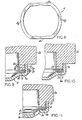
- Fig. 9 is a partial cross-section showing the back cover member snap-fitted to the case at circular arc portions.
- Fig. 10 is a partial cross-section showing the back cover member and case at rectilinear surface portions.
- Fig. 11 is similar to Fig. 10 but also including a diaphragm plate sandwiched between the gasket and back cover member for purpose of alarm sound generation.
- Fig. 12 is a rear plan view of another watchcase, showing a modified form of the invention.
- Fig. 13 is a front plan view of a back cover member for use with the case of Fig. 12.
- Fig. 14 is a plan view of a gasket for use with the case and back cover member of Figs. 12 and 13.
- Fig. 15 is a rear plan view of still another watchcase, showing another form of the invention.
- Fig. 16 is a partial cross-section through a circular arc portion of the case flange of Fig. 15.
- Fig. 17 is a partial cross-section through a rectilinear surface portion of the case flange of Fig. 15.
- Fig. 18 is a front plan view of a back cover member for use with the case of Fig. 15.
- Fig. 19 is a partial cross-section through a circular arc portion of the rim of the back cover member.
- Fig. 20 is a partial cross-section through a rectilinear surface portion of the back cover member.
- Fig. 21 is a plan view of the gasket for use with the case and back cover member of Figs. 15 and 18.
- Figs. 1 and 2 show a
watch case 2 comprising adiecast case band 2a having a pair of spaced apart lugs 2b on opposite sides. Of course, a watch band, strap or bracelet is attached to the lugs by means of a conventional spring bar connector (not shown) having spring-urged pintles which are inserted in holes in the lugs. The case band includes acentral window 2c in the front side to allow viewing of a time display (not shown) housed therein. Of course, the time display may be provided in the form of an electrooptical display, an analog display having rotating hour and minute hands or hybrids thereof, all of which are well known to those skilled in the art and the particular construction of which form no part of the present invention. - The rear side of the
case 2 is shown in Figs. 2 and 3 as comprising a rearperipheral surface 2d, generally flat, and a rearwardly extendingflange 2e defining a rear access opening 2f in the case band. As shown, theflange 2e is characterized by a four-sided polygonal plan profile composed of diametrically opposed first circulararc surface portions 2g having a common center point and parallelrectilinear surface portions 2h connecting the circular arc portions together. In simple, form this polygonal plan profile may be viewed as a truncated circle. For purposes of providing a snap-fit engagement surface on the flange, the exterior peripheral engagement surface 2i of each circular arc surface portion is radially machined to provide a 10° undercut surface as shown most clearly in Fig. 3. By using the case flange with the polygonal plan profile, the circulararc surface portions 2g can be easily and inexpensively radially machined with conventional equipment. This is an important advantage of the present timepiece construction. Therectilinear surface portions 2h need not be subjected to any machining operations.Rectilinear surface portions 2h as well asportions 2g have tapered as-cast "draw" surfaces (Fig 4) to aid in removal of the case band from the diecasting machine. Of course, if the case band is not die cast or molded, thesurface portions back cover member 3 andcase band 2 is effected only at thecircular arc portions 2g. - As shown in Figs. 3 and 4, the
case flange 2e terminates in a sealing surface 2k which contacts thesealing gasket 4 as shown in Figs. 9 and 10. - The
back cover member 3 adapted for use withwatch case 2 is shown in Figs. 5, 6 and 7. The stamped sheet metal back cover member includes aback portion 3a having an inner back surface 3b which faces the watch case when the components are engaged. Extending frontwardly from the back portion isrim 3c which is characterized also by a polygonal plan profile composed of diametrically opposed second circulararc surface portions 3g connected together by a pair of parallelrectilinear surface portions 3h. The circular arc portions are stamped to provide an inner peripheral engagement surface 3i adapted to snap-fit against the exterior engagement surface 2i ofcase flange 2e. In particular, the engagement surface 3i includes an inwardly extendingboss 3m which snaps ontothe undercut engagement surface 2i as shown in Fig. 9. Fig. 7 illustrates that therectilinear surface portions 3h extend frontwardly with generally no taper. Therectilinear surface portions 3h of the rim are in spaced-apart, non-snap-fit relation with therectilinear surface portions 2h on the case flange as shown in Fig. 10. It is apparent that there is no snap-fit engagement between the rectilinear surface portions of the case flange and back cover rim. - Back cover
member 3 is provided with a projecting.lip 3p, Figs. 5 and 9, to facilitate unsnapping of the cover member from thecase 2. - As shown in Figs. 9 and 10, a sealing
gasket 4 is interposed and compressed between the sealing surface 2k of the case flange and the inner back surface 3b (Figs. 5 to 7) of theback cover member 3 to provide resistance to water penetration. The gasket is typically positioned on the inner back surface of the back cover and then the back cover is snap-fitted onto the case flange as described hereinabove. This action compresses the gasket sufficiently to provide a water resistant joint between the case and back cover member. As shown in Fig. 8, the gasket also preferably has a polygonal plan profile at least on the exterior side composed of diametrically opposedcircular arc portions 4g andrectilinear surface portions 4h connecting therebetween. Typically, the sealing gasket is made of well known natural or synthetic rubbers or elastomers made for this purpose. The gasket may have generally flat surfaces for contacting the sealing surface 2k and inner back surface 3b or other cross-sectional configurations, e.g. the gasket surface in contact with sealing surface 2k may have a protruding portion such as a rounded hump or triangular profile extending toward the sealing surface to enhance sealing action therewith. - Fig. 11 is similar to Fig. 10 with the addition that a diaphragm plate 5 carrying a vibrating element 6 such as a piezoelectric element is incorporated into the timepiece. In particular, the diaphragm plate has a annular lip 5a interposed between the
gasket 4 and inside back surface of the back cover member. The back cover member includes one or more holes 3n to provide for alarm sound emission from the timepiece. For example, as is well known in the art, the plate 5 is caused to vibrate by imposition of an electric signal upon element 6 thereby producing an alarm sound at a preselected time, and the sound is emitted through holes 3n. - Figs. 12 to 14 illustrate another embodiment of the invention employing a watchcase 2', back cover member 3' and sealing gasket 4' having surfaces with a four-sided polygonal plan profile. One difference between this embodiment and that described hereinabove is in the orientation of the sides of the polygon relative to the lugs. In Figs. 12 to 14 the rectilinear sides of the polygon extend in the direction of lug extension, whereas in the embodiment described above the
rectilinear sides 2h extend transverse to the lug extension direction. Generally, the watchcase and back cover member of Figs. 12 to 14 include similar features as those described in the above embodiment and like features are represented by like numerals having a prime mark superscript. - In another modification of the invention shown in Figs. 15 to 20 a watchcase 12 and
back cover member 13 with eight-sided snap-fit engagement surfaces are used. As shown, the case includes arearwardly extending flange 12e having a polygonal plan profile composed of fourcircular arc portions 12g with a common center point and fourrectilinear portions 12h. It is apparent that there are two pairs of circular arc portions in diametrically opposed relation. An exterior engagement surface 12i is provided by radially machining a 15° or other angular undercut in the exterior of thecircular arc portions 12g, Fig. 16, while therectilinear portions 12h have generally straight as-cast exterior surfaces, Fig. 17. - The
back cover member 13 includes a flat back portion 13b having similarcircular arc portions 13g andrectilinear portions 13h as thecase flange 12e, although slightly larger in diameter and width. Thecircular arc portions 13g are adapted to snap-fit onto the exterior ofcircular arc portions 12g of the case flange as already described hereinabove with respect to Figs. 9 and 10. To this end, thecircular arc portions 13g have an inner engagement surface 13i with an inwardly projectingboss 13m, Fig. 19,.to snap onto the undercut of the case engagement surface. Therectilinear portions 13h have generally straight inner surfaces and slightly tapered exterior surfaces, Fig. 20. Alip 13p is stamped into each circular arc portion to facilitate unsnapping of the back cover member. - A sealing
gasket 14 for use with the watch case and back cover member of Figs. 15 to 20 is shown in Fig. 21. It is apparent that the gasket is given the eightsided polygonal plan profile includingcircular arc portions 14g andrectilinear portions 14h. The gasket is interposed and compressed between the sealing surface 12k of the case flange and the inside back surface 13b when the case and back cover member are snap-fitted together as described above. - Although the engagement surfaces described hereinabove have been illustrated as having a polygonal plan profile with an even number of sides, it is apparent that polygons with odd- numbered sides may also be employed in the invention. Polygons are defined herein as a closed plane figure bounded by straight lines and/or arcuate lines. Although the polygons are specifically shown hereinabove as composed of circular arc surface portions connected together by rectilinear connecting surface portions, it is apparent that curvilinear surface portions as well as rectilinear portions may also be employed as connecting surfaces. Regardless of the connecting surface employed, it is preferred that the connecting surfaces do not extend outside the circumference of the full circle of which the circular arc portions are a part. And, it is apparent that case manufacturing techniques other than diecasting, e.g. stamping, machining or plastic injection molding may also be employed. The case, of course,, may be made of metal, plastic or of other materials or composites thereof. The back cover member likewise may be machined, plastic injection molded as well as stamped of metal, plastic or composites.
Claims (8)
Applications Claiming Priority (2)
| Application Number | Priority Date | Filing Date | Title |
|---|---|---|---|
| US06/286,423 US4379643A (en) | 1981-07-24 | 1981-07-24 | Timepiece case/backcover assembly |
| US286423 | 1981-07-24 |
Publications (3)
| Publication Number | Publication Date |
|---|---|
| EP0070969A2 EP0070969A2 (en) | 1983-02-09 |
| EP0070969A3 EP0070969A3 (en) | 1983-03-30 |
| EP0070969B1 true EP0070969B1 (en) | 1986-03-26 |
Family
ID=23098540
Family Applications (1)
| Application Number | Title | Priority Date | Filing Date |
|---|---|---|---|
| EP82103346A Expired EP0070969B1 (en) | 1981-07-24 | 1982-04-21 | Timepiece case/backcover assembly |
Country Status (5)
| Country | Link |
|---|---|
| US (1) | US4379643A (en) |
| EP (1) | EP0070969B1 (en) |
| JP (1) | JPS5826289A (en) |
| CA (1) | CA1163100A (en) |
| DE (1) | DE3270062D1 (en) |
Families Citing this family (6)
| Publication number | Priority date | Publication date | Assignee | Title |
|---|---|---|---|---|
| DE29714637U1 (en) * | 1997-06-16 | 1998-02-26 | Timehouse Handelsgesellschaft mbH, 20259 Hamburg | Clocks |
| USD431202S (en) * | 1998-04-07 | 2000-09-26 | Rado Watch Co. Ltd | Back cover of a watch with a variable pattern |
| JP2002082182A (en) * | 2000-07-06 | 2002-03-22 | Seiko Precision Inc | Built-in clock |
| USD452061S1 (en) | 2001-07-31 | 2001-12-18 | Nike, Inc. | Portion of a shoe outsole |
| US6890125B1 (en) | 2002-01-30 | 2005-05-10 | Calder Brothers Corporation | Adjustable screed system |
| EP3499320A1 (en) | 2017-12-15 | 2019-06-19 | The Swatch Group Research and Development Ltd | Opening/closing system for a timepiece case |
Family Cites Families (5)
| Publication number | Priority date | Publication date | Assignee | Title |
|---|---|---|---|---|
| DE1438693U (en) * | 1938-04-30 | 1938-06-23 | ||
| US2350651A (en) * | 1940-10-25 | 1944-06-06 | Taubert Marcel | Watchcase |
| FR1239947A (en) * | 1959-04-30 | 1960-09-02 | Etablissements Frainier Soc D | Watertight closing watch box |
| CH617562B5 (en) * | 1977-12-09 | 1982-05-28 | Piquerez Sa Ervin | WATERPROOF SHAPE WATCH BOX. |
| US4241442A (en) * | 1979-08-02 | 1980-12-23 | Timex Corporation | Timepiece with shaped components |
-
1981
- 1981-07-24 US US06/286,423 patent/US4379643A/en not_active Expired - Fee Related
-
1982
- 1982-04-14 CA CA000400934A patent/CA1163100A/en not_active Expired
- 1982-04-21 EP EP82103346A patent/EP0070969B1/en not_active Expired
- 1982-04-21 DE DE8282103346T patent/DE3270062D1/en not_active Expired
- 1982-07-19 JP JP57125592A patent/JPS5826289A/en active Pending
Also Published As
| Publication number | Publication date |
|---|---|
| EP0070969A3 (en) | 1983-03-30 |
| DE3270062D1 (en) | 1986-04-30 |
| EP0070969A2 (en) | 1983-02-09 |
| JPS5826289A (en) | 1983-02-16 |
| US4379643A (en) | 1983-04-12 |
| CA1163100A (en) | 1984-03-06 |
Similar Documents
| Publication | Publication Date | Title |
|---|---|---|
| US4462697A (en) | Integral plastic strap and bezel for a wristwatch | |
| US10025273B2 (en) | Timepiece | |
| JPH0333680A (en) | Wrist watch | |
| US20080049560A1 (en) | Watch casing integrally formed with watch band | |
| US4241442A (en) | Timepiece with shaped components | |
| US4188778A (en) | Caseback with noncircular, multilobed snap-fit surface | |
| US4379643A (en) | Timepiece case/backcover assembly | |
| JP2020169839A (en) | Exterior member, case, and timepiece | |
| US4432476A (en) | Band attachment assembly for attaching a watchband to a watchcase | |
| JP6003027B2 (en) | Dial structure and watch | |
| US20080025157A1 (en) | Timepiece | |
| US4403870A (en) | Water-resistant shaped case construction for a wristwatch | |
| JPH0743883Y2 (en) | Push button assembly structure | |
| US4397567A (en) | Timepiece construction with a caseback removable using a credit card | |
| KR100313271B1 (en) | Watch with a rotating bezel | |
| GB1516270A (en) | Watchcase and push switch assembly for electronic watch | |
| US20070147184A1 (en) | Timepiece | |
| US4529323A (en) | Leak resistant watch casing having annular elastic element surrounding a casing ring which centers the watch movement relative to the casing | |
| GB2135082A (en) | Improvements in clocks | |
| US4205523A (en) | Case body construction for timepieces | |
| US4217752A (en) | Fixing structure of back cover for watch | |
| GB1565930A (en) | Watch case for a battery operated watch | |
| US3020703A (en) | Sealed watch case | |
| KR930002905A (en) | Integral caseband-bezel, attachment lug and back cover | |
| JP2784398B2 (en) | Exterior structure such as watches |
Legal Events
| Date | Code | Title | Description |
|---|---|---|---|
| PUAI | Public reference made under article 153(3) epc to a published international application that has entered the european phase |
Free format text: ORIGINAL CODE: 0009012 |
|
| PUAL | Search report despatched |
Free format text: ORIGINAL CODE: 0009013 |
|
| AK | Designated contracting states |
Designated state(s): CH DE FR GB IT LI |
|
| AK | Designated contracting states |
Designated state(s): CH DE FR GB IT LI |
|
| 17P | Request for examination filed |
Effective date: 19830601 |
|
| GRAA | (expected) grant |
Free format text: ORIGINAL CODE: 0009210 |
|
| AK | Designated contracting states |
Kind code of ref document: B1 Designated state(s): CH DE FR GB IT LI |
|
| ITF | It: translation for a ep patent filed | ||
| ET | Fr: translation filed | ||
| REF | Corresponds to: |
Ref document number: 3270062 Country of ref document: DE Date of ref document: 19860430 |
|
| PLBE | No opposition filed within time limit |
Free format text: ORIGINAL CODE: 0009261 |
|
| STAA | Information on the status of an ep patent application or granted ep patent |
Free format text: STATUS: NO OPPOSITION FILED WITHIN TIME LIMIT |
|
| 26N | No opposition filed | ||
| PG25 | Lapsed in a contracting state [announced via postgrant information from national office to epo] |
Ref country code: GB Effective date: 19880421 |
|
| PG25 | Lapsed in a contracting state [announced via postgrant information from national office to epo] |
Ref country code: LI Effective date: 19880430 Ref country code: CH Effective date: 19880430 |
|
| GBPC | Gb: european patent ceased through non-payment of renewal fee | ||
| PG25 | Lapsed in a contracting state [announced via postgrant information from national office to epo] |
Ref country code: FR Free format text: LAPSE BECAUSE OF NON-PAYMENT OF DUE FEES Effective date: 19881229 |
|
| REG | Reference to a national code |
Ref country code: CH Ref legal event code: PL |
|
| PG25 | Lapsed in a contracting state [announced via postgrant information from national office to epo] |
Ref country code: DE Effective date: 19890103 |
|
| REG | Reference to a national code |
Ref country code: FR Ref legal event code: ST |