EP0070794A2 - Circuit breaker with vacuum switch - Google Patents
Circuit breaker with vacuum switch Download PDFInfo
- Publication number
- EP0070794A2 EP0070794A2 EP82730094A EP82730094A EP0070794A2 EP 0070794 A2 EP0070794 A2 EP 0070794A2 EP 82730094 A EP82730094 A EP 82730094A EP 82730094 A EP82730094 A EP 82730094A EP 0070794 A2 EP0070794 A2 EP 0070794A2
- Authority
- EP
- European Patent Office
- Prior art keywords
- contact
- spring
- disconnector
- switch
- buffer
- Prior art date
- Legal status (The legal status is an assumption and is not a legal conclusion. Google has not performed a legal analysis and makes no representation as to the accuracy of the status listed.)
- Withdrawn
Links
Images
Classifications
-
- H—ELECTRICITY
- H01—ELECTRIC ELEMENTS
- H01H—ELECTRIC SWITCHES; RELAYS; SELECTORS; EMERGENCY PROTECTIVE DEVICES
- H01H33/00—High-tension or heavy-current switches with arc-extinguishing or arc-preventing means
- H01H33/60—Switches wherein the means for extinguishing or preventing the arc do not include separate means for obtaining or increasing flow of arc-extinguishing fluid
- H01H33/66—Vacuum switches
- H01H33/666—Operating arrangements
- H01H33/6661—Combination with other type of switch, e.g. for load break switches
-
- H—ELECTRICITY
- H01—ELECTRIC ELEMENTS
- H01H—ELECTRIC SWITCHES; RELAYS; SELECTORS; EMERGENCY PROTECTIVE DEVICES
- H01H33/00—High-tension or heavy-current switches with arc-extinguishing or arc-preventing means
- H01H33/02—Details
- H01H33/04—Means for extinguishing or preventing arc between current-carrying parts
- H01H33/12—Auxiliary contacts on to which the arc is transferred from the main contacts
- H01H33/121—Load break switches
- H01H33/125—Load break switches comprising a separate circuit breaker
- H01H33/127—Load break switches comprising a separate circuit breaker movable with a sectionalising contact arm and operated by such movement
-
- H—ELECTRICITY
- H01—ELECTRIC ELEMENTS
- H01H—ELECTRIC SWITCHES; RELAYS; SELECTORS; EMERGENCY PROTECTIVE DEVICES
- H01H9/00—Details of switching devices, not covered by groups H01H1/00 - H01H7/00
- H01H9/10—Adaptation for built-in fuses
- H01H9/102—Fuses mounted on or constituting the movable contact parts of the switch
Definitions
- the invention relates to a load switch with a vacuum switch according to the preamble of patent claim 1.
- load switches must be able to switch the load currents on and off. When arranged in control panels or the like. easy detection of the open state of the circuit breaker and a small space requirement are required. Such load switches should also be able to withstand a large number of switching operations, i.e. be durable, which requires an arc-free switching. Small, long-life vacuum switches which can be switched without arcing are known, but because of their very small electrode spacings in the open state, e.g. With switches for 2.7 kV less than 10 mm, the open switching status cannot be recognized safely and easily, especially when used in control panels.
- the invention has for its object to provide a durable, small-sized, arc-free switchable switch of the type mentioned, the respective switching state, in particular its open state, can be easily and safely visually detected and which can be used for many switching operations.
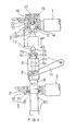
- An upper support insulator 1 and a lower support insulator 2 are attached to a frame (not shown).
- a receptacle contact 4 of the disconnector 3 connected to a connection terminal 22 is held and on the lower support insulator 2, a sliding contact 5 connected to a connection terminal 21 is held, both lying on a common longitudinal axis.
- An actuating unit of the load switch adjustable in the direction of the longitudinal axis projects through the sliding contact 5.
- This longitudinally adjustable actuating unit consists of a vacuum switch 6 with a fixed electrode 6c and a control rod 6b which is guided out of the vacuum switch and can be adjusted in the axial direction against the force of a hold-open spring 10 and has an attached electrode 6a.
- an intrusion contact 7 of the disconnector. 3 with annular bead 7b projecting over the control rod 6b on the circumferential side and a rod flange 7a, between which and the vacuum switch 6 the hold-open spring 10 is clamped.
- the section between the rod flange 7a and the annular bead 7b is, as will be explained further below, as an annular groove for one Retention device 12a used in the receiving contact 4.
- a rod-shaped fuse 9 which projects through the sliding contact 5 in the axial direction and is used in its upper end position for power supply, is mechanically firmly connected to the fixed electrode 6c in the axial direction as a conductive connecting element.
- the rod-shaped fuse 9 is provided at its free end with a contact cap 9a and connected to a mechanical coupling member 8 which is in engagement with a crank mechanism 11 which is actuated by a rotary drive, not shown, so that the longitudinally adjustable actuating unit from the fully drawn Can be brought into the position indicated by dash-dotted lines and vice versa.
- the contact cap 9a comes into engagement with the sliding contact 5 and the penetration contact 7 of the isolating switch 3 engages with the stationary receiving contact 4 of the isolating switch 3.
- the stationary receiving contact 4 of the isolating switch 3 consists of contact pieces 12 arranged coaxially to the longitudinal axis within a contact piece holder 13 connected to the connecting terminal 22, which are held together by a surrounding contact ring spring 14 with their free end projections 12a as a retaining device for the actuating unit towards the longitudinal axis.
- a buffer 16 Arranged in the contact piece holder 13 above the contact pieces 12 is a buffer 16 projecting between them, which is supported by a contact buffer spring 15 on a conductive fixed stop 17 of the contact piece holder 13.
- the sliding contact 5 consists of the fuse 9 coaxially surrounding contact pieces 18, which are held together by a contact ring spring 20 in an electrically conductive contact piece holder 19, which in turn is attached to the support insulator 2 and is connected to the terminal 21.
- the hold-open spring 10 is designed in terms of its spring force f 3 so that it keeps the electrodes 6a and 6c of the vacuum switch 6 separate from one another when the disconnector 3 is open.
- the spring force f 3 of the hold-open spring 10 is sufficient when introducing the penetration contact 7 into the receiving contact 4 (arrow direction P) and spreading the contact pieces 12 through the annular bead 7b around the electrodes 6a, 6c against the spring force component f 1 of the contact ring spring acting in the opposite arrow direction Q 14 continue to be kept separate.
- the hold-open spring 10 is also only pressed together by the opposite spring force f 4 of the contact buffer spring 15 when the penetration contact 7 strikes the buffer 16, the electrodes 6a and 6c making contact.
- the spring force f 1 of the contact ring spring 14 is designed so that it not only ensures a certain current transfer between the penetration contact 7 and the contact pieces 12, but also temporarily the engagement between their retaining end projections 12a and the said annular groove between the annular bead 7b and the rod flange 7a maintains during the disconnection movement of the disconnector 3 in the opposite arrow direction Q.
- the electrodes 6a, 6c are disconnected before the disconnector 3 opens.
- the spring force f 4 of the contact buffer spring 15 is greater than the spring force f 3 of the hold-open spring 10, the reverse force ratio f ' 3 , f' 4 can also be increased with increased spring force f3 f 3 f4 can be provided as long as the fixed stop 17 is present. In this case, the driving force G f ' 3 + f 2 .
- FIG. 3 A simplified embodiment with a lighter actuating unit is shown in FIG. 3, in which the unchanged parts corresponding to FIG. 1 have the same reference numerals. Only the parts identified by reference numerals 23, 24 and 25 are new or modified.
- the main difference from the embodiment according to FIG. 1 is that the receiving contact 24 of the disconnector 3 is part of the actuating unit.
- the crank mechanism 11 is in turn connected to the fuse 9 via the coupling member 8.
- a contact piece holder 25 for the contact pieces 12 forming the adjustable receiving contact 24 of the disconnector 3 is arranged, in which the buffer 16, the contact buffer spring 15 and the fixed stop 17 are accommodated in the same way as in FIG. 1.
- An L-shaped support 23 for the immovable vacuum switch 6, which is conductively connected to the connecting terminal 22, is held on the upper support insulator 1.
- the electrode 6c is conductively connected to the connection terminal 22 via the carrier 23.
- a well-conductive, appropriately dimensioned Ku p ferrohr can be used, which can transmit the highest occurring current properly and without risk of damage from the sliding contact to the load or disconnector.
Abstract
Ein Trennschalter (3) und ein Vakuumschalter (6) sind elektrisch in Reihe geschaltet und in Achsrichtung verstellbar, wobei die bewegliche Elektrode (6a) des Vakuumschalters (6) mit dem Eindringkontakt (7) des Trennschalters (3) fest verbunden und ein Verbindungselement (9) in Achsrichtung verstellbar in Eingriff mit einem Schleifkontakt (5) kommt und die Trennschalterkontakte (4, 24; 7) relativ zueinander verstellbar sind.A disconnector (3) and a vacuum switch (6) are electrically connected in series and adjustable in the axial direction, the movable electrode (6a) of the vacuum switch (6) being firmly connected to the penetration contact (7) of the disconnector (3) and a connecting element ( 9) adjustable in the axial direction comes into engagement with a sliding contact (5) and the isolating switch contacts (4, 24; 7) are adjustable relative to one another.
Description
Die Erfindung betrifft einen Lastschalter mit einem Vakuumschalter nach dem Oberbegriff des Patentanspruchs 1.The invention relates to a load switch with a vacuum switch according to the preamble of
Bekanntlich müssen Lastschalter die auftretenden Lastströme zu- und abschalten können. Bei Anordnung in Schalttafeln od.dgl. wird eine leichte Erfassung des geöffneten Zustandes des Lastschalters sowie ein geringer Raumbedarf gefordert. Solche Lastschalter sollen ferner eine Vielzahl von Schalthandlungen aushalten können, d.h. langlebig sein, was ein lichtbogenloses Schalten voraussetzt. Es sind zwar kleinbauende, lichtbogenlos schaltbare langlebige Vakuumschalter bekannt, die aber wegen ihrer nur sehr geringen Elektrodenabstände im geöffneten Zustand, z.B. bei Schaltern für 2,7 kV weniger als 10 mm, den offenen Schaltzustand nicht sicher und leicht erkennen lassen, insbesondere bei Verwendung in Schalttafeln.As is known, load switches must be able to switch the load currents on and off. When arranged in control panels or the like. easy detection of the open state of the circuit breaker and a small space requirement are required. Such load switches should also be able to withstand a large number of switching operations, i.e. be durable, which requires an arc-free switching. Small, long-life vacuum switches which can be switched without arcing are known, but because of their very small electrode spacings in the open state, e.g. With switches for 2.7 kV less than 10 mm, the open switching status cannot be recognized safely and easily, especially when used in control panels.
Bei Luft-Trennschaltern mit hin- und herbewegten oder rotierenden Kontakten kann wegen ausreichend großer Distanz zwischen den Schaltkontakten zwar der offene Schaltzustand durch Augenschein leicht erfaßt werden, jedoch treten beim Betätigen solcher Trennschalter vielfach Lichtbögen auf, die die Lebensdauer solcher Trennschalter beeinträchtigen.In air circuit breakers with reciprocating or rotating contacts, the open switching state can be easily detected by visual inspection because of the sufficiently large distance between the switching contacts, but arcing often occurs when such circuit breakers are actuated, which impair the service life of such circuit breakers.
Der Erfindung liegt die Aufgabe zugrunde, einen langlebigen, kleinbauenden, lichtbogenlos schaltbaren Lastschalter der eingangs genannten Art zu schaffen, dessen jeweiliger Schaltzustand, insbesondere sein offener Zustand, leicht und sicher visuell erfaßt werden kann und der für viele Schalthandlungen verwendbar ist.The invention has for its object to provide a durable, small-sized, arc-free switchable switch of the type mentioned, the respective switching state, in particular its open state, can be easily and safely visually detected and which can be used for many switching operations.
Die Lösung der gestellten Aufgabe gelingt nach der Erfindung durch die kennzeichnenden Merkmale des Patentanspruchs 1The object is achieved according to the invention by the characterizing features of
Vorteilhafte Weiterbildungen der Erfindung sind Gegenstand zusätzlicher Ansprüche.Advantageous developments of the invention are the subject of additional claims.
Zwei Ausführungsbeispiele der Erfindung sind nachfolgend anhand der Zeichnung näher erläutert. Es zeigen
- Fig. 1 einen maßgeblichen Teil des Lastschalters im geöffneten Zustand,
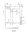
- Fig. 2 die Zusammenhänge zwischen den verschiedenen Lagen der beweglichen Schalterteile und den Feder- und Reibkräften,
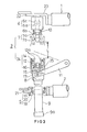
- Fig. 3 eine abgewandelte Ausführung eines Lastschalters im geöffneten Zustand.
- 1 shows a significant part of the circuit breaker in the open state,
- 2 shows the relationships between the different positions of the movable switch parts and the spring and friction forces,
- Fig. 3 shows a modified version of a circuit breaker in the open state.
An einem nicht dargestellten Gestell sind ein oberer Tragisolator 1 und ein unterer Tragisolator 2 befestigt. Am oberen Tragisolator 1 ist ein an eine Anschlußklemme 22 angeschlossener Aufnahmekontakt 4 des Trennschalters 3 und am unteren Tragisolator 2 ein an eine Anschlußklemme 21 angeschlossener Schleifkontakt 5 gehalten, wobei beide auf einer gemeinsamen Längsachse liegen. Eine in der Richtung der Längsachse verstellbare Stelleinheit des Lastschalters ragt durch den Schleifkontakt 5. Diese längsverstellbare Stelleinheit besteht aus einem Vakuumschalter 6 mit einer Festelektrode 6c und einer aus dem Vakuumschalter herausgeführten, in Achsrichtung gegen die Kraft einer Offenhaltefeder 10 verstellbaren Steuerstab 6b mit daran befestigter Elektrode 6a. Am äußeren Ende des Steuerstabes 6b ist ein Eindringkontakt 7 des Trennschalters. 3 mit über den Steuerstab 6b umfangsseitig überstehenden Ringwulst 7b sowie ein Stabflansch 7a befestigt, zwischen dem und dem Vakuumschalter 6 die Offenhaltefeder 10 eingespannt ist. Der Abschnitt zwischen dem Stabflansch 7a und dem Ringwulst 7b ist, wie weiter unten noch erläutert wird, als Ringnut für eine Rückhaltevorrichtung 12a im Aufnahmekontakt 4 benutzt. Mit der Festelektrode 6c ist in Achsrichtung als leitendes Verbindungselement eine stabförmige Schmelzsicherung 9 mechanisch fest verbunden, die durch den Schleifkontakt 5 in Achsrichtung ragt und die in ihrer oberen Endstellung zur Stromzuführung mitbenutzt ist. Die stabförmige Schmelzsicherung 9 ist hierzu an ihrem freien Ende mit einer Kontaktkappe 9a versehen und mit einem mechanischen Koppelglied 8 verbunden, das mit einem Kurbelmechanismus 11 in Eingriff steht, der von einem nicht gezeigten Drehantrieb betätigt wird, so daß die längsverstellbare Stelleinheit aus der voll gezeichneten Lage in die strichpunktiert angedeutete Lage und umgekehrt gebracht werdeb kann. In der strichpunktiert gezeigten Lage kommt die Kontaktkappe 9a in Eingriff mit dem Schleifkontakt 5 und der Eindringkontakt 7 des Trennschalters 3 in Eingriff mit dem ruhenden Aufnahmekontakt 4 des Trennschalters 3.An
Der ruhende Aufnahmekontakt 4 des Trennschalters 3 besteht aus innerhalb eines mit der Anschlußklemme 22 verbundenen Kontaktstückhalters 13 koaxial zur Längsachse angeordneten Kontaktstücken 12, die durch eine sie umgebende Kontaktringfeder 14 mit ihren freien Endvorsprüngen 12a als Rückhaltevorrichtung für die Stelleinheit zur Längsachse hin zusammengehalten werden. Im Kontaktstückhalter 13 ist oberhalb der Kontaktstücke 12 ein zwischen diese ragender Puffer 16 angeordnet, der sich über eine Kontaktpufferfeder 15 an einem leitenden Festanschlag 17 des Kontaktstückhalters 13 abstützt.The stationary receiving
In ähnlicher Weise besteht der Schleifkontakt 5 aus die Schmelzsicherung 9 koaxial umgebenden Kontaktstücken 18, die durch eine Kontaktringfeder 20 zusammengehalten in einem elektrisch leitenden Kontaktstückhalter 19 angeordnet sind, der seinerseits am Tragisolator 2 befestigt und mit der Anschlußklemme 21 verbunden ist.Similarly, the sliding
Die Offenhaltefeder 10 ist in ihrer Federkraft f3 so ausgelegt, daß sie bei geöffnetem Trennschalter 3 die Elektroden 6a und 6c des Vakuumschalters 6 voneinander getrennt hält. Die Federkraft f3 der Offenhaltefeder 10 reicht beim Einbringen des Eindringkontaktes 7 in den Aufnahmekontakt 4 (Pfeilrichtung P) und Aufspreizen der Kontaktstücke 12 durch den Ringwulst 7b aus um die Elektroden 6a, 6c gegen die in Gegen-Pfeilrichtung Q wirkende Federkraftkomponente f1 der Kontaktringfeder 14 weiterhin voneinander getrennt zu halten. Die Offenhaltefeder 10 wird außerdem durch die entgegengesetzte Federkraft f4 der Kontaktpufferfeder 15 erst dann zusammengepreßt, wenn der Eindringkontakt 7 am Puffer 16 anschlägt, wobei sich die Elektroden 6a und 6c kontaktgebend berühren.The hold-
Die Federkraft f1 der Kontaktringfeder 14 ist dabei so ausgelegt, daß sie nicht nur einen bestimmten Stromübergang sicherstellt zwischen dem Eindringkontakt 7 und den Kontaktstücken 12, sondern auch vorübergehend den Eingriff zwischen deren rückhaltenden Endvorsprüngen 12a und der besagten Ringnut zwischen dem Ringwulst 7b und dem Stabflansch 7a aufrechterhält bei der Trennbewegung des Trennschalters 3 in Gegen-Pfeilrichtung Q. Dabei werden die Elektroden 6a, 6c vor dem öffnen des Trennschalters 3 getrennt.The spring force f 1 of the
Mit der Trennung des Eindringkontaktes 7 von den Kontaktstücken 12 wird eine sichtbare, ausreichende Lufttrennstrecke L zwischen den Kontakten des Trennschalters 3 erhalten.With the separation of the
In Fig. 2 sind die Zusammenhänge zwischen den Stellungen der gemeinsam längsachsverstellbaren Schalterteile 6, 7 und 9 (Stelleinheit) und den Kräften f2, f5 sowie den Federkräften f1, f3, f4 der Federn 10, 14 und 15 beim öffnen und Sthließen der Schalterkontakte dargestellt. In der Ordinatenachse sind die Änderungen der Kräfte und in der Abszissenachse die Lage der Stelleinheit angegeben.In Fig. 2, the relationships between the positions of the common longitudinal axis
Von der Anfangsposition F ausgehend, bei der der in Pfeilrichtung P aus der in Fig. 1 voll ausgezogenen Offenstellung verschobene Eindringkontakt 7 in den Aufnahmekontakt 4 eingeführt wird und dabei der Ringwulst 7b die Endvorsprünge 12 aufspreizt (Schließbetätigung), wird die in Gegen-Pfeilrichtung Q wirksame Kraft f1 der Kontaktringfeder 14 auf die Stelleinheit voraussetzungsgemäß nicht ausreichen, um die Elektroden 6a, 6c in Berührung zu bringen. Beim Weiterbewegen der Stelleinheit gelangt der Ringwulst 7b in der Position E.außer Eingriff mit den Endvorsprüngen 12a, wobei die Federkraft f1 in die geringere Reibkraft f2 zwischen den Kontaktstücken 12 und dem Ringwulst 7b übergeht.Starting from the initial position F, in which the
Bei weiterer Verstellung des Eindringkontaktes 7 bis zur Position D, bei der die Stirnseite des Kontaktkopfes 7b an dem Puffer 16 anliegt (wie in Fig. 1 strichpunktiert angedeutet), wird der Eindringkontakt 7 relativ in die Gegen-Pfeilrichtung Q verstellt, da die Federkraft f3 der Offenhaltefeder 10 geringer als die Federkraft f4 der Kontaktpufferfeder 15 ausgelegt ist. Dadurch wird die bewegliche Elektrode 6a gegen die Festeleketrode 6c verstellt und kommt in Position B in Kontakt mit dieser. Der weitergehende Verstellvorgang bringt den Eindringkontakt 7 noch weiter nach oben, so daß seine Stirnseite den Puffer 16 gegen die Kraft der Kontaktpufferfeder 15 in seine Endlage bringt, bei der er in Position A am Festanschlag 17 anliegt, womit der Verstellvorgang des Trennschalters 3 beendet ist. In dieser Endstellung der Stelleinheit wird diese durch eine nicht gezeigte Arretierung gehalten.Upon further adjustment of the
Bei der Verstellung der Stelleinheit über die Position D zur Position B über eine nachfolgend beschriebene Position C treten keine relativen Bewegungen zwischen der Ringwulst 7b und den Kontaktstücken 12 auf, so daß der Eindringkontakt 7 nicht mehr der Reibkraft f2 ausgesetzt ist. Dagegen unterliegt der Eindringkontakt 7 wiederum der Reibkraft f2 bei Verstellung von der Position B in die Position A. Deshalb muß auf den Kurbelmechanismus 11 in Pfeilrichtung P eine Antriebskraft G ausgeübt werden, die größer als die Summe der Federkraft f4 der Kontaktpufferfeder 15 und der Reibkraft f2 ist, d.h. G f4+ f2.When adjusting the actuating unit via position D to position B via a position C described below, there are no relative movements between the
Wenn die nicht gezeigte Arretierung freigegeben und die Stelleinheit zum öffnen des Schalters in Gegen-Pfeilrich- . tung Q bewegt wird, unterliegt der Eindringkontakt 7 einer Differenzkraft f4 - f2. Diese Differenzkraft bringt den Puffer 16 aus seiner Position A (Endlage) in Gegen-Pfeilrichtung Q. Danach spannt die Reibkraft f2 die Offenhaltefeder 10, so daß der Eindringkontakt 7 rückwärts bis in die Position C gelangt, in der der Ringwulst 7b durch die Rückhaltevorrichtung 12a festgehalten wird durch deren Rückhaltekraft f5 f3 der Offenhaltefeder 10.When the locking device, not shown, is released and the actuating unit for opening the switch in the opposite arrow direction. device Q is moved, the
Der Eindringkontakt 7 samt Elektrode 6a werden vorübergehend in ihrer Bewegung in Gegen-Pfeilrichtung Q gestoppt, so daß daher nur der Vakuumschalter 6 samt Festelektrode 6c und die Schmelzsicherung 9 zur Position D hin bewegt werden. In der Position D sind die Elektroden 6a, 6c weitestgehend voneinander entfernt und unterbrechen den Stromfluß. Danach wird der Eingriff des Ringwulstes 7b mit der Rückhaltevorrichtung 12a gelöst durch die fortwährend einwirkende Antriebskraft G f5' so daß die Stelleinheit in ihre in Fig. 1 gezeigte endgültige Offenstellung gelangt. Damit die Trennbewegung des Trennschalters 3 nicht einsetzt, bevor die Elektroden 6a, 6c ihre relativ gegensinnige öffnungsbewegung beendet haben, muß die Rückhaltekraft f5 f3 der Offenhaltefeder 10 bemessen sein.The penetration contact 7 together with the
Obwohl im oben erläuterten Ausführungsbeispiel mit beweglichem Puffer 16 und Festanschlag 17 die Federkraft f4 der Kontaktpufferfeder 15 größer bemessen ist als die Federkraft f3 der Offenhaltefeder 10, kann auch das umgekehrte Kräfteverhältnis f'3, f'4 bei vergrößerter Federkraft f3 f3 f4 vorgesehen werden, solange der Festanschlag 17 vorhanden ist. In diesem Fall gilt für die Antriebskraft G f'3 + f2.Although in the exemplary embodiment explained above with a
Eine vereinfachte Ausführungsform mit leichterer Stelleinheit ist in Fig. 3 gezeigt, in der die mit Fig. 1 übereinstimmenden unveränderten Teile die gleichen Bezugszeichen haben. Nur die mit den Bezugszeichen 23, 24 und 25 bezeichneten Teile sind neu bzw. abgeändert.A simplified embodiment with a lighter actuating unit is shown in FIG. 3, in which the unchanged parts corresponding to FIG. 1 have the same reference numerals. Only the parts identified by
Der wesentliche Unterschied zur Ausführung nach Fig. 1 besteht darin, daß der Aufnahmekontakt 24 des Trennschalters 3 Teil der Stelleinheit ist. Mit der Schmelzsicherung 9 ist über das Koppelglied 8 wiederum der Kurbelmechanismus 11 verbunden. Am oberen Ende der längsverstellbaren stromleitenden Schmelzsicherung 9 ist ein Kontaktstückhalter 25 für die den verstellbaren Aufnahmekontakt 24 des Trennschalters 3 bildenden Kontaktstücke 12 angeordnet, in dem der Puffer 16, die Kontaktpufferfeder 15 und der Festanschlag 17 in gleicher Weise wie in Fig. 1 untergebracht sind. Am oberen Tragisolator 1 ist ein mit der Anschlußklemme 22 leitend verbundener L-förmiger Träger 23 für den unbeweglichen Vakuumschalter 6 gehalten. Der nach unten ragende, unter der Kraft der Offenhaltefeder 10 stehende Eindringkontakt 7 kommt mit dem nach oben axial verstellbaren Aufnahmekontakt 24 des Trennschalters in vergleichbarer Weise in Eingriff wie beim erstgenannten Ausführungsbeispiel. Die Elektrode 6c ist über den Träger 23 mit der Anschlußklemme 22 leitend verbunden.The main difference from the embodiment according to FIG. 1 is that the receiving
Da der Vakuumschalter 6 schwerer als der Kontaktstückhalter 25 bzw. 13 (Fig. 1) ist, ergibt sich eine leichtere Stelleinheit als bei der Anordnung nach Fig. 1. Es genügt daher eine entsprechend kleiner dimensionierte Antriebsvorrichtung und es ergibt sich außerdem eine längere Lebensdauer für die Schalteranordnung und eine erhöhte Sicherheit bei verbesserter Handhabung, so daß diese Ausführung mit besonderem Vorteil bei Schalttafeln verwendet werden'kann. Die Bemessung der Federkräfte ist entsprechend vorzunehmen.Since the
In beiden Fällen kann statt der stabförmigen Schmelzsicherung 9 auch ein gut leitendes, entsprechend bemessenes Kupferrohr benutzt werden, das den höchstauftretenden Strom einwandfrei und ohne Gefahr der Beschädigung vom Schleifkontakt zum Last- bzw. Trennschalter übertragen kann.In both cases, instead of the rod-
Claims (7)
Applications Claiming Priority (2)
| Application Number | Priority Date | Filing Date | Title |
|---|---|---|---|
| JP111152/81 | 1981-07-16 | ||
| JP56111152A JPS5812230A (en) | 1981-07-16 | 1981-07-16 | Vacuum laod switch with disconnecting switch |
Publications (2)
| Publication Number | Publication Date |
|---|---|
| EP0070794A2 true EP0070794A2 (en) | 1983-01-26 |
| EP0070794A3 EP0070794A3 (en) | 1984-11-07 |
Family
ID=14553773
Family Applications (1)
| Application Number | Title | Priority Date | Filing Date |
|---|---|---|---|
| EP82730094A Withdrawn EP0070794A3 (en) | 1981-07-16 | 1982-07-05 | Circuit breaker with vacuum switch |
Country Status (7)
| Country | Link |
|---|---|
| US (1) | US4484044A (en) |
| EP (1) | EP0070794A3 (en) |
| JP (1) | JPS5812230A (en) |
| DK (1) | DK317682A (en) |
| ES (1) | ES514070A0 (en) |
| NO (1) | NO822420L (en) |
| PT (1) | PT75238B (en) |
Cited By (19)
| Publication number | Priority date | Publication date | Assignee | Title |
|---|---|---|---|---|
| DE3412399A1 (en) * | 1984-04-03 | 1985-10-10 | Sachsenwerk, Licht- und Kraft-AG, 8000 München | Three-position switch |
| DE3447314A1 (en) * | 1984-12-24 | 1986-06-26 | Calor-Emag Elektrizitäts-Aktiengesellschaft, 4030 Ratingen | Device for a vacuum interrupter |
| EP0212136A2 (en) * | 1985-08-23 | 1987-03-04 | Concordia Sprecher GmbH | Earthing switch disposition for high-tension installations |
| DE4015979A1 (en) * | 1990-05-18 | 1991-11-21 | Sachsenwerk Ag | Switch combination esp. for transformers on ring mains - incorporates vacuum switch which cannot be closed is load isolator with energy store is already engaged |
| WO1995022832A1 (en) * | 1994-02-18 | 1995-08-24 | Brian Mckean Associates Ltd. | Sequential isolating circuit breaker and actuator |
| GB2301227A (en) * | 1994-02-18 | 1996-11-27 | Mckean Brian Ass Ltd | Sequential isolating circuit breaker and actuator |
| WO1998009310A1 (en) * | 1996-08-26 | 1998-03-05 | Elektrotechnische Werke Fritz Driescher & Söhne Gmbh | Load interrupter switch |
| EP0843330A2 (en) * | 1996-11-15 | 1998-05-20 | Kabushiki Kaisha Toshiba | Disconnector-fitted vacuum breaker |
| EP0780867A3 (en) * | 1995-12-21 | 1998-10-21 | Gec Alsthom Limited | Vacuum switching device |
| DE19859007A1 (en) * | 1998-12-21 | 2000-06-29 | Abb Patent Gmbh | Load isolation switch has first contact point with fixed contact arrangement and movable contact arrangement in form of linearly movable thrust tube containing movable vacuum chamber |
| US6130394A (en) * | 1996-08-26 | 2000-10-10 | Elektrotechnische Weke Fritz Driescher & Sohne GmbH | Hermetically sealed vacuum load interrupter switch with flashover features |
| EP1102296A2 (en) * | 1999-11-17 | 2001-05-23 | ABBPATENT GmbH | Circuit breaker |
| FR2817655A1 (en) * | 2000-12-01 | 2002-06-07 | Alstom | SAFETY DEVICE APPLIED TO THE CONNECTION AND RELEASE OF A FUSE IN A MEDIUM VOLTAGE ELECTRICAL EQUIPMENT |
| DE102005013231B3 (en) * | 2005-03-18 | 2006-09-21 | Siemens Ag | Cam profile switch |
| EP1826791A2 (en) | 2006-02-23 | 2007-08-29 | Eaton Corporation | Three-position vacuum interrupter disconnect switch providing current interruption, disconnection and grounding |
| DE102007038898B3 (en) * | 2007-08-13 | 2008-11-20 | Siemens Ag | Switch arrangement for a switchgear |
| US7679019B2 (en) | 2006-03-09 | 2010-03-16 | Switchcraft Europe Gmbh | Electrical switching system |
| DE102011079969A1 (en) | 2011-07-28 | 2013-01-31 | Siemens Aktiengesellschaft | switchgear |
| EP2665077A1 (en) * | 2012-05-14 | 2013-11-20 | ABB Technology AG | High current switching device |
Families Citing this family (16)
| Publication number | Priority date | Publication date | Assignee | Title |
|---|---|---|---|---|
| GB2260027A (en) * | 1991-09-30 | 1993-03-31 | Long & Crawford Limited | Electrical switchgear |
| US10361802B1 (en) | 1999-02-01 | 2019-07-23 | Blanding Hovenweep, Llc | Adaptive pattern recognition based control system and method |
| US8352400B2 (en) | 1991-12-23 | 2013-01-08 | Hoffberg Steven M | Adaptive pattern recognition based controller apparatus and method and human-factored interface therefore |
| GB2300305B (en) * | 1995-04-27 | 1999-04-28 | Gec Alsthom Ltd | Circuit interrupter arrangement |
| US5889248A (en) * | 1997-09-08 | 1999-03-30 | Abb Power T&D Company Inc. | Operating mechanism for combined interrupter disconnect switch |
| US7966078B2 (en) | 1999-02-01 | 2011-06-21 | Steven Hoffberg | Network media appliance system and method |
| IT1309626B1 (en) * | 1999-11-03 | 2002-01-30 | Vei Electric Systems Spa | SECTIONING AND INTERRUPTION DEVICE, FOR ELECTRICAL CABINETS. |
| CN100337375C (en) * | 2000-08-30 | 2007-09-12 | 日本能源服务株式会社 | Switch insulation component |
| EP2117025B1 (en) * | 2008-05-06 | 2012-12-19 | ABB Technology AG | Medium voltage switch unit |
| US9076602B2 (en) | 2010-07-07 | 2015-07-07 | Kaon Holdings Pty Ltd | Electrical isolator |
| CN103198963A (en) * | 2012-04-17 | 2013-07-10 | 苏州朗格电气有限公司 | Vacuum circuit breaker |
| CN102623219A (en) * | 2012-04-23 | 2012-08-01 | 苏州朗格电气有限公司 | Disconnecting switch and vacuum circuit breaker composite system |
| RU168739U1 (en) * | 2016-10-26 | 2017-02-17 | Закрытое акционерное общество "Группа компаний "Электрощит"-ТМ Самара" | HIGH VOLTAGE LOAD CIRCUIT BREAKER |
| KR101984197B1 (en) * | 2017-12-11 | 2019-05-30 | 주식회사 스위코 | Composite insulated switchgear circuit |
| KR101966602B1 (en) * | 2018-12-05 | 2019-08-13 | (주)이플전기 | Insulated housing type interlocking disconnector and vacuum valve |
| US10872739B2 (en) * | 2019-05-24 | 2020-12-22 | Frank P Stacom | Methods and systems for DC current interrupter based on thermionic arc extinction via anode ion depletion |
Citations (4)
| Publication number | Priority date | Publication date | Assignee | Title |
|---|---|---|---|---|
| US3038980A (en) * | 1959-12-17 | 1962-06-12 | Gen Electric | Vacuum-type circuit interrupter |
| GB1112745A (en) * | 1965-12-03 | 1968-05-08 | Ass Elect Ind | Improvements in and relating to circuit breakers |
| US3399286A (en) * | 1966-03-07 | 1968-08-27 | Powerdyne Inc | High voltage electric swtich |
| US4281228A (en) * | 1979-04-02 | 1981-07-28 | Harmon Robert W | Tool for making and breaking load currents |
Family Cites Families (5)
| Publication number | Priority date | Publication date | Assignee | Title |
|---|---|---|---|---|
| GB1107855A (en) * | 1965-07-02 | 1968-03-27 | Licentia Gmbh | Improvements in vacuum switch assemblies |
| CH469341A (en) * | 1968-01-17 | 1969-02-28 | Gardy Sa | Gas jet arc blow switch |
| US3597713A (en) * | 1969-01-03 | 1971-08-03 | Esco Mfg Co | Current responsive circuit breaker with releasable coupling means, and with circuitry means disposed within a hollow terminal |
| US3848101A (en) * | 1969-09-26 | 1974-11-12 | Ite Imperial Corp | Elongated jaw contact for oil circuit breaker disconnect contact |
| US3646294A (en) * | 1970-12-31 | 1972-02-29 | Itt | Switch |
-
1981
- 1981-07-16 JP JP56111152A patent/JPS5812230A/en active Granted
-
1982
- 1982-07-05 EP EP82730094A patent/EP0070794A3/en not_active Withdrawn
- 1982-07-13 NO NO822420A patent/NO822420L/en unknown
- 1982-07-13 PT PT75238A patent/PT75238B/en unknown
- 1982-07-15 DK DK317682A patent/DK317682A/en not_active Application Discontinuation
- 1982-07-15 US US06/398,655 patent/US4484044A/en not_active Expired - Fee Related
- 1982-07-16 ES ES514070A patent/ES514070A0/en active Granted
Patent Citations (4)
| Publication number | Priority date | Publication date | Assignee | Title |
|---|---|---|---|---|
| US3038980A (en) * | 1959-12-17 | 1962-06-12 | Gen Electric | Vacuum-type circuit interrupter |
| GB1112745A (en) * | 1965-12-03 | 1968-05-08 | Ass Elect Ind | Improvements in and relating to circuit breakers |
| US3399286A (en) * | 1966-03-07 | 1968-08-27 | Powerdyne Inc | High voltage electric swtich |
| US4281228A (en) * | 1979-04-02 | 1981-07-28 | Harmon Robert W | Tool for making and breaking load currents |
Cited By (28)
| Publication number | Priority date | Publication date | Assignee | Title |
|---|---|---|---|---|
| DE3412399A1 (en) * | 1984-04-03 | 1985-10-10 | Sachsenwerk, Licht- und Kraft-AG, 8000 München | Three-position switch |
| DE3447314A1 (en) * | 1984-12-24 | 1986-06-26 | Calor-Emag Elektrizitäts-Aktiengesellschaft, 4030 Ratingen | Device for a vacuum interrupter |
| EP0212136A2 (en) * | 1985-08-23 | 1987-03-04 | Concordia Sprecher GmbH | Earthing switch disposition for high-tension installations |
| EP0212136A3 (en) * | 1985-08-23 | 1989-05-03 | Concordia Sprecher Schaltgerate Gmbh | Earthing switch disposition for high-tension installations |
| DE4015979A1 (en) * | 1990-05-18 | 1991-11-21 | Sachsenwerk Ag | Switch combination esp. for transformers on ring mains - incorporates vacuum switch which cannot be closed is load isolator with energy store is already engaged |
| DE4015979C2 (en) * | 1990-05-18 | 1998-04-30 | Sachsenwerk Ag | Switch combination for load switchgear |
| WO1995022832A1 (en) * | 1994-02-18 | 1995-08-24 | Brian Mckean Associates Ltd. | Sequential isolating circuit breaker and actuator |
| GB2301227A (en) * | 1994-02-18 | 1996-11-27 | Mckean Brian Ass Ltd | Sequential isolating circuit breaker and actuator |
| GB2301227B (en) * | 1994-02-18 | 1997-10-08 | Mckean Brian Ass Ltd | Sequential isolating circuit breaker and actuator |
| EP0780867A3 (en) * | 1995-12-21 | 1998-10-21 | Gec Alsthom Limited | Vacuum switching device |
| US6130394A (en) * | 1996-08-26 | 2000-10-10 | Elektrotechnische Weke Fritz Driescher & Sohne GmbH | Hermetically sealed vacuum load interrupter switch with flashover features |
| WO1998009310A1 (en) * | 1996-08-26 | 1998-03-05 | Elektrotechnische Werke Fritz Driescher & Söhne Gmbh | Load interrupter switch |
| EP0843330A2 (en) * | 1996-11-15 | 1998-05-20 | Kabushiki Kaisha Toshiba | Disconnector-fitted vacuum breaker |
| EP0843330A3 (en) * | 1996-11-15 | 1999-03-03 | Kabushiki Kaisha Toshiba | Disconnector-fitted vacuum breaker |
| DE19859007A1 (en) * | 1998-12-21 | 2000-06-29 | Abb Patent Gmbh | Load isolation switch has first contact point with fixed contact arrangement and movable contact arrangement in form of linearly movable thrust tube containing movable vacuum chamber |
| EP1102296A2 (en) * | 1999-11-17 | 2001-05-23 | ABBPATENT GmbH | Circuit breaker |
| EP1102296A3 (en) * | 1999-11-17 | 2003-01-15 | ABB PATENT GmbH | Circuit breaker |
| FR2817655A1 (en) * | 2000-12-01 | 2002-06-07 | Alstom | SAFETY DEVICE APPLIED TO THE CONNECTION AND RELEASE OF A FUSE IN A MEDIUM VOLTAGE ELECTRICAL EQUIPMENT |
| US6624996B2 (en) | 2000-12-01 | 2003-09-23 | Alstom | Safety device applied to engaging and disengaging a fuse in medium voltage electrical gear |
| DE102005013231B3 (en) * | 2005-03-18 | 2006-09-21 | Siemens Ag | Cam profile switch |
| EP1826791A2 (en) | 2006-02-23 | 2007-08-29 | Eaton Corporation | Three-position vacuum interrupter disconnect switch providing current interruption, disconnection and grounding |
| EP1826791B1 (en) * | 2006-02-23 | 2020-04-01 | Eaton Corporation | Three-position vacuum interrupter disconnect switch providing current interruption, disconnection and grounding |
| US7679019B2 (en) | 2006-03-09 | 2010-03-16 | Switchcraft Europe Gmbh | Electrical switching system |
| DE102007038898B3 (en) * | 2007-08-13 | 2008-11-20 | Siemens Ag | Switch arrangement for a switchgear |
| WO2009021882A1 (en) * | 2007-08-13 | 2009-02-19 | Siemens Aktiengesellschaft | Switch arrangement for a switchgear assembly |
| DE102011079969A1 (en) | 2011-07-28 | 2013-01-31 | Siemens Aktiengesellschaft | switchgear |
| WO2013014070A1 (en) | 2011-07-28 | 2013-01-31 | Siemens Aktiengesellschaft | Switching device |
| EP2665077A1 (en) * | 2012-05-14 | 2013-11-20 | ABB Technology AG | High current switching device |
Also Published As
| Publication number | Publication date |
|---|---|
| US4484044A (en) | 1984-11-20 |
| PT75238B (en) | 1984-11-19 |
| DK317682A (en) | 1983-01-17 |
| ES8305529A1 (en) | 1983-04-01 |
| NO822420L (en) | 1983-01-17 |
| JPS6314806B2 (en) | 1988-04-01 |
| EP0070794A3 (en) | 1984-11-07 |
| ES514070A0 (en) | 1983-04-01 |
| JPS5812230A (en) | 1983-01-24 |
| PT75238A (en) | 1982-08-01 |
Similar Documents
| Publication | Publication Date | Title |
|---|---|---|
| EP0070794A2 (en) | Circuit breaker with vacuum switch | |
| DE3411275C2 (en) | ||
| EP0876671B1 (en) | Electrical switching device | |
| DE2831134C2 (en) | Metal-enclosed, pressurized gas-insulated high-voltage switchgear | |
| EP0500550B1 (en) | Isolator switch for metal-clad, compressed-gas-insulated high-voltage switchgear | |
| DE2231516A1 (en) | END CLOSURE MODULE FOR ELECTRIC CABLE WITH GAS TRAP VALVE | |
| DE3242014A1 (en) | GAS-INSULATED CIRCUIT-DISCONNECTOR - SWITCH | |
| EP2728602A1 (en) | Electrical high voltage circuit breaker and method for opening same | |
| DE2704389B2 (en) | Disconnector for metal-enclosed high-voltage switchgear | |
| WO2000003406A1 (en) | Current contact system for a current switch | |
| DE19740490C1 (en) | Isolating switch for interrupting the current in a conductor in the event of a short circuit or excessive current | |
| DE2356515C2 (en) | Electrodynamic switching device such as relay, contactor or the like. | |
| EP0734580B1 (en) | High-voltage power switch with a field electrode | |
| DE3736835A1 (en) | High-voltage switch | |
| DE19851226C2 (en) | disconnectors | |
| EP0091082B1 (en) | Electromagnetically operable switching device | |
| DE19813177C1 (en) | Electric switch, esp. medium voltage switch for power supply networks | |
| DE2206120A1 (en) | High voltage electrical switch | |
| DE3235353C2 (en) | ||
| DE3237146C2 (en) | ||
| DE2525082B2 (en) | Switch disconnector | |
| DE102018109750A1 (en) | switching device | |
| DE19649979C1 (en) | High-voltage switchgear electrodynamic drive system | |
| DE3033935A1 (en) | ELECTRIC SWITCH | |
| DE3114837C2 (en) |
Legal Events
| Date | Code | Title | Description |
|---|---|---|---|
| PUAI | Public reference made under article 153(3) epc to a published international application that has entered the european phase |
Free format text: ORIGINAL CODE: 0009012 |
|
| AK | Designated contracting states |
Designated state(s): BE DE IT NL SE |
|
| PUAL | Search report despatched |
Free format text: ORIGINAL CODE: 0009013 |
|
| STAA | Information on the status of an ep patent application or granted ep patent |
Free format text: STATUS: THE APPLICATION HAS BEEN WITHDRAWN |
|
| AK | Designated contracting states |
Designated state(s): BE DE IT NL SE |
|
| 18W | Application withdrawn |
Withdrawal date: 19841030 |
|
| RIN1 | Information on inventor provided before grant (corrected) |
Inventor name: YOSHIGAE, KIYOHISA |